Drives on hard magnetic Winchester drives are designed for long-term storage information in the computer. The hard drive received the name HDD in 1973, when IBM manufactured a sealed package of two replaceable disks of 30 MB each. The numbers 30/30 were associated with the caliber of the popular Winchester 30/30 shotgun in the United States. In 1983, PC XT computers began to be equipped with non-removable hard drives with a capacity of 10 MB with an average access time of 100 ms.
And if we can, we must start the recovery software from a different drive than trying to scan the deleted file. All of them are searched. deleted filesfrom which we can know the state and whether they can be restored or not. In other words, you can manually configure only one system, create one image of this system and then deploy it to all other computers, saving time and cost. Simple wizard interface - no in-depth knowledge of computer management is required. All other writes to the disk are cached until the image is created. Image file data is also restored on the fly, with the exception of the system partition. The boot version can use a graphical user interface or pseudo-graphic mode if the graphics card is not supported. Keep in mind: incremental back up the hard drive should not be too large. Network support in the boot version. Extended list of supported devices in the boot version. The image file can be mounted as a read-only virtual disk. This disk can be scanned, and your files and folders can be found and copied. Restore individual files and folders. Individual files and folders can be restored instead of the entire drive, either during the restore action, or from an image file attached to virtual disk. Separation of image files. Disk images can be divided into several files for placement on a storage device. Image protection. Disk image files can be password protected and contain comments. Create a new section. Data from a disk image can be recovered in free space of any place on a hard disk. The size of the restored partition can be changed. Partition replacement. Data from a disk image can be restored to other existing partitions. Copy from disk to disk. One disk can be copied directly to another disk. Checking image files. You can check if your image files are good before storing or restoring data from them. Timetable. Time to create a disk image can be scheduled, and the process can run in silent mode. Scripts for frequent or quiet actions. You can create a disk or volume image of any type and restore the image to a dynamic or base disk. When this image is restored, you will not be able to resize or other characteristics of the target disk.
- A significant increase in the speed of reading compressed images.
- Faster and more reliable disk processing engine.
Magnetic drive made of aluminum alloy or glass plates with a diameter of 3.5 or 2.5 with a thickness of 0.125 inches. Several thin layers of magnetic and non-magnetic materials are applied to the plates by sputtering, which are able to magnetize on small areas of the surface. The plates are mounted on the axis of a small spindle silent motor (D), which rotates at a constant speed (Fig. 4.3). Due to restrictions on the size and weight of the HDD used in the composition personal computer, the number of plates is limited and currently does not exceed 12.
This is the amount you can buy in the Czech Republic for an extremely powerful gaming computer or a new car. They do not contain moving parts, which makes them much faster against classic drives. This is known in practice when opening files and when starting a computer.
Double sided design for continuous operation
This does not increase the noise inside the cabinet, unlike hard drives, which in some cases is the loudest component of a computer. However, for most laptops, installing two drives is not possible. This is important to protect data on individual devices and the scalability of the business continuity needs.
Most often, the number of plates is from two to four (heads from 4 to 8), and the outer discs sometimes have only one internal working surface. Typically, discs have lower and upper working surfaces. One read / write head (Г1, ..., Гn) is brought to each working surface. The heads are manufactured using thin-film technology and are special semiconductor crystals with a U-shaped gap facing the plate. The U-shape is used to create lift due to air movement during the rotation of the discs. The head hovers above the surface with a gap calculated in microns.
Missing Mode Protection
As shown in the figure above, the cable connection method used to connect the expansion modules creates a redundant cross-sectional configuration. The system can be restored from the missing mode to its normal state, and the data will be saved.
High density, high performance and high scalability.
This solution delivers unprecedented performance up to 48 Gbps for connecting a single host computer.
Reliable implementation right after connection
Environmental friendliness and ease of management. You can manually configure deep sleep mode to automatically start after a period of inactivity. This not only saves energy, but also extends the service life. hard drive.Fig. 4.3. HDD Scheme
Currently, drives larger than 1 GB use magnetoresistive heads (MR), which include a thin-film head (TF) for recording and magnetoresistive for reading. TFs are micro-coils of several turns on a miniature printed circuit board. Inside the coil is a core made of an alloy of nickel and iron with high induction. The gap in the core by spraying is filled with non-magnetic aluminum and is protected from damage during contact with the disk. To prevent damage to the plates from particles entering the gap between the head and the working surface, the disks are placed in a sealed enclosure filled with inert gas.
It is characterized by reliability, durability and stable parameters in continuous operation - it is an excellent choice for the implementation of video surveillance systems. It is standard in size and can work at relatively high temperatures, so it can be installed in large registers, where several disks work.
Effective work in monitoring systems. It has been optimized in such a way that it can record high-definition images of up to 32 cameras at the same time - this is an excellent choice for small and medium-sized surveillance systems. Additional drive benefits that enhance its usability.
The lightness of the head and the small gap between the disk and the head (about 15 nm) make it possible to magnetize the track deep into the surface of the disk, ensuring the reliability of recording / reading and storage of information. The second part of the MR head is a read head, which is based on a sensor resistor that changes its resistance depending on the magnitude of the magnetic field. Through the resistor, a constant measuring current flows, which changes from the magnetic field at moments t sz when moving along the track. To reduce interference from adjacent tracks, the resistor is raised above the track. Installing heads on given i the track (a cylinder with a diameter of di for all plates) is made by a solenoid coil (K) moving the drive handle (P), as shown in
fig. 4.3. To move the heads to the necessary track, a signal Ei is applied to the automatic tracking system (CS), which is compared with the signal xcoming from a special head (G) or a contact of variable resistance R. If there is a difference in the compared signals, the SU moves the stock (W) of the solenoid in the direction of the required diameter di. When the power is turned off, the hard drive automatically parks with a spring (P) moving the heads to the inner area of \u200b\u200bthe disk, usually to the last track. The number of tracks is determined by the type of drive and for hard drives their number is several thousand. The small gap between the head and the surface of the disk allows you to achieve a high radial and linear recording density (100 Gbit / sq. Inch) and increase the capacity of the hard disk to several tens or even hundreds of GB.
This minimizes the number of illegible or completely lost image frames. This feature is absolutely essential for monitoring systems. It is easy to imagine a situation where several key frames do not make the entire record unreadable. An additional benefit of speed optimization is noise reduction and the absence of strong vibration, so that the disc wears out more slowly and reduces the risk of damage. Collaboration with most registrars.
Therefore, they can be installed inside any registrar that is included in our offer. See how the history of hard drives looked like hard disks have changed over the years. From huge sizes to small appliances. Low to high power.
The main parameters of the hard drive are capacity (E), exchange rate (V CR) and data access time (t cf.). The capacity of any drive is directly proportional to the size of the forms - factor (size). Form - factor indicates the section of the compartment for the hard drive. If it is equal to 3.5 ´ 1, then this corresponds to the 4 ´ 1 ´ 6-inch bay used for one 3.5² hard drive. The larger the size of the disks and their number in the package, the greater the capacity. However, with an increase in the diameter of the plates on different tracks, the speed of the disk relative to the heads changes significantly, the time for moving the heads from the internal track to the external and average access times increases. These parameters limit the manufacture of discs larger than 3.5. Therefore, an increase in disk capacity is constantly happening due to an increase in TPI, BPI and encoding - decoding methods. In addition, increasing the recording density allows you to increase the speed of reading data at the same speed of rotation of the disk. Thus, Fujutsu in the new 3.5 HDD model reached a density of 10.2 GB on one 3.5 plate with MR heads and a PRML channel. This company produces silent HDDs using liquid friction bearings. Other companies produce plates with a recording density of 20 GB or more per plate.
It had 80 columns with one sign and rectangular openings. It is made of hard thin cardboard with a thickness of only 0.18 mm. The stack of two thousand cards was 355 millimeters thick. The computer read the system of holes punched on the card, and then saved the data to the hard drive. After a dozen readings, the card was so worn out that it could be replaced.
The punch card inventor is Joseph Jacquard. He used it for the first time in a weaving knot for flow control. The goal was to create a repeating fabric. It was created to replace the storage mechanism on perforated cards. The computer has surpassed many of what we know today. He occupied the whole room, and his work was constantly monitored by three people.
The exchange rate is characterized by two parameters: the transfer rate between the HDD and RAM and the transfer speed between the hard drive buffer and the surface disk V d. The transfer rate between the HDD and RAM is measured by the value of V ol (Mb / s) as the ratio of the transferred array to the time spent on sending it. It is determined mainly by the type of interface.
There were 100 concentric paths on each side, and each of them contained 500 alphanumeric characters. The first storage on disk can store 5 million characters. Disk read time is less than a second. Data was recorded on 40 tracks, and the entire drum had a capacity of 10,000. Characters. In years, computing systems even weighed several tons. Computer equipment weighed hundreds of kilograms, and hard drives of this size corresponded to refrigerators.
Capacity increase, size reduction
He had the advantage of taking a little less space here than a washing machine. Department of computers, electronics and automation. Stefan cel Mare University, Suceava, Romania. Continuous advances in this area over the past 55 years have been driven by three important factors: an increase in storage density, an increase in the speed of data processing, and a reduction in production costs. Based on these data, it is noticeable that the storage of the information bit is based on nanoscale thin-film structures.
2.1. Data transfer modes
Two modes are used to transfer data between the hard drive and PC memory:
PIO program input / output mode;
DMA direct access mode.
In PIO mode, information from the cache buffer (Winchester RAM) of the hard disk is first read by the central processor and only then written to the main RAM. Depending on the length of the read cycle and the number of sectors transferred per one disk access, the modes PIO0 (PIO Mode 0), PIO1, PIO2, PIO3, PIO4, PIO5 are distinguished. The characteristics of the PIO modes are given in table. 4.3.
In addition to the interest in recording density areas, it is important to focus on data rates hard drives. Thus, the recording time of one bit or the equivalent of the magnetization inversion time is less than 1 ns. The difference in transition resistance corresponds to a stable parallel and antiparallel orientation, which allows you to determine the binary state of the memory.
Thin-film ferromagnetic electrodes have nanometric dimensions, and the magnetization switching time has values \u200b\u200bin nanoseconds. In nanomagnetic memory cells, thermal fluctuations can lead to magnetization to another minimum of energy, and therefore the stored information is lost.
In PIO mode, the contents of one sector (512 bytes) are usually transferred per HDD access, and in PIO 4 mode, 16 (or more) sectors are transferred. This helps to increase the data transfer rate from 3.3 Mb in PIO 0 mode to 20 Mb / s in PIO 5 mode using IDE or EIDE interfaces.
However, PIO mode is traditionally used in single task operating systemsoh. In multi-tasking operating systems, direct access to random access memory DMA Data input / output in this mode is carried out in the PC RAM, bypassing the MP. The exchange takes place under the control of the HDD controller in the pauses between calls of the MP to RAM, which underestimates the exchange rate, but frees the MP from the data transfer operation between RAM and HDD. For DMA modes, special controllers and drivers are used. DMA modes are divided into single-word DMA 0,1,2 (Singleword) and verbose DMA 33,100 (Multiword) depending on the number of words transmitted per one cycle of work with the system bus. The characteristics of the early methods of implementing DMA are presented in table. 4.4.
HDD schematic diagram
The induced phenomenon of thermal fluctuations, the so-called superparamagnetic effect, is increasing more and more with decreasing particle size and is a key limitation in further improving the storage density of hard drives and random access magnetic storage devices. The project director made a significant contribution to characterizing the first three alternative recording technologies from the critical field and switching time. He also addressed several issues related to the design of magnetic field pulses suitable for these records.
To ensure greater DMA performance, Ultra DMA / 33 mode was developed and implemented at the beginning. The Quantum Ultra ATA / 33 interface (Ultra DMA / 33 and ATA-33) offers data transfer in Multiword DMA mode at a speed of 33 Mb / s. Unlike the DMA 2 mode, in the Ultra АТА / 33 mode (Fig. 4.4.) Data is transmitted on the leading and trailing edges of the clock signal (TI). This allows you to 2 times increase the transmission speed without increasing the clock frequency of the system bus. The Ultra DMA / 33 standard differs from previous versions of the IDE not only in the exchange rate. For the first time, it uses an error detection mechanism using a cyclic control code.
However, the results were obtained by neglecting thermal effects. One of the main goals of this proposal is to study the thermal stability of new recording methods and the influence of thermal noise, as well as other types of noise on the alternative recording technologies mentioned above.
A special case is represented by a thermal record, which is trying to capitalize on the inversions caused by thermal fluctuations, by local heating of the nanoscale of interest. In addition to the interest in the negative effects of noise and vibrations, special attention is paid to the design effects of noise in hysteresis systems. Since noise is an undesirable effect in linear systems and in many non-linear electronic devices, its potential benefits are quite contrary to intuition, which long time ignored by the researchers.
With the advent of Pentium processors, EIDE controllers provide the Bus Master function. This is due to the fact that in multitasking operating systems, to increase the speed of computing, the MP is freed from data input / output between RAM and HDD. Therefore, the controllers of external devices (including EIDE) began to be equipped with their own input / output microprocessors. In this case, the MP issues a command to the EIDE controller, which tells him where it should take the data from and in which memory area it should be placed. After receiving these instructions, the controller takes control of the system bus (PCI) and performs operations on reading data from information storage devices (for example, from a hard drive, CD-ROM, CD-R, CD-RW drives) directly to RAM using the DMA channel. However, the gain in PC performance when using the Bus Master function will be significant only if several applications work simultaneously. The Bus Master function is supported by almost all modern chipsets.
This phenomenon is commonly known as coherent resonance, when it is induced only by noise and stochastic resonance, when an external oscillator signal is present. In conclusion, the stochastic analysis developed by this project will go to the reconnaissance and resonance of induced noise in non-linear systems and to hold harsh conditions to obtain resonance phenomena in spintronic devices and semiconductors.
The third area of \u200b\u200binterest for our project is the analysis of noise and vibration effects in nanoscale semiconductor devices. The prevailing trends in silicon electronics are: an increase in the speed and frequency of operation of analog and digital components, a decrease in current consumption in electronic circuits, and an increase in functionality on a single silicon chip. However, it is well known that these small devices are very sensitive to vibrations of random doping inevitably present due to the random nature of ion implantation and diffusion, as well as the characteristic geometric vibrations from one device to another.
|
|
|
|
|
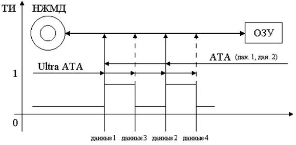
Fig. 4.4. Principle of data transfer in ATA and Ultra ATA / 33 interfaces
Lecture 16: I / O device interfaces
IDEIDE (ATA), EIDE (Fast ATA, ATA-2, ATA-3) and SCSI have long been used as the interface of a hard drive with a system bus on the system board. The first Compaq and Western Digital IDEs integrated on the hard drive for 8/16 bit ISA AT type computers, called the IDE ATA and released in 1986, were standardized in 1990 to serve two hard drives. The IDE interface quickly gained popularity among PC manufacturers and users. At the same time, the cost of the hard drive increased slightly, and the hard drive began to connect directly to the slot on the system board, which is a truncated ISA bus slot, or to the adapter board. Previously, the HDD controller was integrated on the adapter board, and parallel and / or serial interfaces and a game port were located. In new motherboards, all these components are integrated directly into one of the VLSI chipset. The most important idea in creating an IDE is to assemble the main parts of the controller board in the HDD itself and ensure compatibility with any motherboards. It is designed for one-time processing of one program input / output procedure in the PIO - 0, PIO - 1, PIO - 2 modes. In the CHS format, the capacity limit of the HDD with the IDE is determined by the product
Ё max \u003d C ´ H ´ S (cylinders x heads x sectors)
Ё max \u003d 65 536 ´ 16 ´ 255 ´ 512 (bytes) \u003d 139.9 GB. However, the BIOS standard for motherboards most recently supported only E max \u003d C ´ H ´ S \u003d 1024 ´ 255 ´ 63 ´ 512 (bytes) \u003d 8.4 GB. Taking into account the joint limitations of IDE and BIOS on the values \u200b\u200bof C, H, S limited the maximum capacity of the HDD without the corresponding software equal to
Ё max \u003d 1024 ´ 16 ´ 63 ´ 512 (bytes) \u003d 504 Mb.
504 MB HDD capacities are already in the computer with i486 was not enough, so the ATE IDE was improved. The new EIDE standard allows you to expand the maximum capacity limit of the HDD.
Eide (Fast ATA) (Western Digital's trade name) PIO-3 and MultiWord DMA1 with multiple-word transmission in direct access to RAM memory. Improved Fast ATA2 supports the modes: PIO-4 and MultiWord DMA 2. The new, with a modified BIOS, the EIDE standard through the EIDE controller can double / quadruple the number of heads with a proportional reduction in the number of cylinders. This allows you to expand the maximum capacity limit of the HDD to 8.4 GB or more due to the implementation of the LBA logical address mode when the FA< C, H, S > translates to a 28 bit logical address< C *, H *, S * >. However, when using FAT, there is a problem limiting disk capacity. It consists in the fact that with an increase in disk capacity, the minimum cluster size (the number of exchange sectors and the smallest recording capacity) increases from 8 KB (for hard drives up to 504 MB) to 64 KB with large-capacity disks. With small file sizes, these clusters are not fully populated. Memory is used inefficiently.
The number of connected devices to EIDE can reach four, including CD - ROM or tape drives. The new EIDE modes allow for 1 exchange to read data containing several (2, 4, 8, 16 and more) standard 512 - byte sectors (Multiple) at once. And the new IDE interface (ATA - 3) supports the Ultra DMA standard and allows you to increase the speed of Ultra DMA exchange of hard drives with RAM via the Ultra DMA controller on the system board. In Ultra mode, the exchange speed corresponds to: DMA 0 - 16.6 Mb / s; DMA 1 - 24.9 Mb / s; DMA 2 (DMA 33) - 33.3 Mb / s; Ultra ATA / 66 - 66.6 Mb / s; Ultra ATA / 100 - 100 Mb / s. New serial 4-wire interface Serial ATA-1.6 with the exchange speed (3 or 6) Gb / s is being developed to further increase the speed of the computer and compatibility with the parallel interfaceIDE.
SCSI was designed to increase the speed of exchange of external devices with the system bus and the number of connected peripherals for multi-tasking and multi-user operating systems. It connects via the main adapter to the PCI and has an 8/16 bit data bus. Devices are connected to the SCSI bus, which are set to ID \u003d 0, 1, ..., 7. ID numbers allow devices to exchange via SD without the participation of MPs using SCSI formats and commands. The SCSI interface supports Еmax \u003d 8.4 GB. By increasing the speed of the exchange (“fast” - fast) and the width of the expansion bus (“wide” - multi-bit), it has the following modifications:
SCSI-1 - 8 bit / up to 5 Mb / s;
Fast SCSI (SCSI - 2) - 8 bit / up to 10 Mb / s;
Ultra SCSI - 8 bit / up to 20 Mb / s;
Fast Wide SCSI - 16 bit / up to 20 Mb / s;
Ultra Wide SCSI (SCSI - 3) - 16 bit / up to 40 Mb / s;
Ultra 160 SCSI - 160 Mb / s;
Ultra 320 SCSI - 320 Mb / s.
In almost all versions of SCSI, a multi-segment cache buffer with a capacity of more than 512 KB is installed to simultaneously serve several competing I / O processes. The SCSI interface has several advantages over the ATA interface:
Ability to connect up to 27 devices (for example, Ultra SCSI-III);
Ability to connect internal and external devices;
Disks of SCSI hard drives rotate at an increased speed of 7200, 10000 or 15 000 rpm, and the access time to them is less than 5 - 7 ms;
The 50-core SCSI ribbon cable can be up to 6 meters long.
Having in its composition better equipment, SCSI is 1.5 times more expensive than ATA and is most often used in servers.
2.3. Interlive
In modern hard drives, the interlining parameter (the number of disk revolutions for reading the entire track), or as it is also called the Interleave factor (Fig. 4.5), does not significantly affect the speed of the exchange if there is sufficient cache buffer memory. However, consideration of this parameter allows us to describe the principle of exchanging the hard drive sectors with a cache buffer. When the disk rotates, the head reads the 512-byte sector and sends data to the buffer register of the controller, from where the data is transferred to the processor. The disk continues to rotate, the read head moves to the next sector, but the controller, with a limited cache buffer, is still busy exchanging data with the processor. Therefore, in order to read the next sector when the controller is released, the head must wait for a full disk revolution or skip part of the sectors. When reading the entire cluster, which is located in neighboring sectors, sectors are read in a row, without delay. If the buffer capacity is small and it is necessary to transfer data to RAM, then part of the sectors is skipped until the buffer is freed. So, in the 3: 1 mode (Fig. 4.5, b) two sectors are skipped.
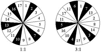
Fig. 4.5. Cluster allocation in 1: 1 and 3: 1 exchange mode
The disks of earlier releases are organized so that the sectors of the data file are not located on the track of the disk one after the other, but in a different order, taking into account the interlining and the ability to exchange with the MP with the rotation of the HDD. Moreover, when positioning the head, the controller has enough time to transmit information without unnecessary disk rotation. When the controller is released, it refers to the corresponding sector.
Modern controllers work on a different principle: to organize continuous reading of sectors, data is read from several sectors ("with suspicion" of their necessity) and stored in a cache buffer, from where they can later be retrieved. The advantage of this method is that the controller is placed in a drive in which the mechanics and electronics work optimally.
The speed of data transfer V d between the Winchester buffer and the surface of the disk, in addition to the search time for the desired track t cp, is significantly affected by: the rotation speed of the plates V in; the number of physical sectors S per track; the method of their alternation (interlive); cache buffer size; data type (sequential, fragmented) and exchange mode. Therefore, the speed V d exchange between the Winchester buffer and the disk surface in the best models usually does not exceed 10 Mb / s. If the track is already positioned, then the exchange rate is mainly determined by two values: the sector search time (equal to half of the plate rotation period T) and the sector read speed. Given these values, V d is approximately determined by the formula:
V d \u003d 0.5 ´ S ´ 512 / (T ´ I) (Kb / s),
where S is the number of physical sectors (S \u003d 80 - 160 and depends on the track number);
T \u003d 1 / V in - period of rotation (at V in \u003d 7,200 rpm T »8 ms);
I - interval, the number of revolutions of the disk to read the entire track (for the best hard drives I \u003d 1).
Substituting the best disk parameters, we get V d »160 ´ 0.5 ´ 512/8 ´ 1024 \u003d 5 Mb / s. When taking into account the search time for the desired track t c, the exchange rate between the Winchester’s cache buffer and the disk surface V d will be less and will be determined by the way the plates are filled. Plates can be filled sequentially (first one disc, then another, etc.) or in the mode of filling tracks, when all the outermost tracks of all plates are filled first, then the recording is shifted to the center. The mode of filling tracks is more common, and therefore, non-filled HDDs are faster than filled ones, because the information on the internal tracks is read slower, and the number of sectors on the tracks is not the same - on the inner cylinders there are fewer than on the external cylinders.
2.4. HDD Features
Typical block - HDD control circuit located on printed circuit board Winchester is shown in Fig. 4.6. Any IDE or SCSI hard drive has a package of magnetic disks, a block of magnetoresistive heads, a positioning system, a read channel for writing, a data separator and a microcontroller. The data separator extracts synchronization pulses and data from the input signal to be read. The microcontroller recognizes identification fields and sector data by special address labels. The identifier field contains encoded information about the sector address< C, H, S >. MP establishes the correct positioning of the heads and performs micro-write / read operations as follows.
Digital system The UM HDD receives commands from the system bus from the central processor through the microcontroller for the disk exchange with the SCSI bus and includes a sector buffer for temporary storage of data involved in the exchange. MP UU drive receives the logical address coming from the system bus< C *, H *, S * >converts it to a physical address< С, H, S >, and, through the MP and the controller for controlling the engine and the drive of the heads, position the corresponding cylinder C. Why is the value determining the place< C > cylinder on plate Ei, compared with the position signal of the drive handle x (see fig. 4.3). If there is a non-zero difference Ei - x a signal arrives from the control system, which amplifies and excites the current in the solenoid K, moving the head drive deeper or to the edge of the disk, depending on the sign of the mismatch value.
Moving, the drive knob reduces the value of Ei - x to zero and MP HDD by the position of the marker (by the identification field code) connects the required head to the sector< S > and a write / read channel including an encoder for recording or a pulse detector and a decoder (DC) in read mode.
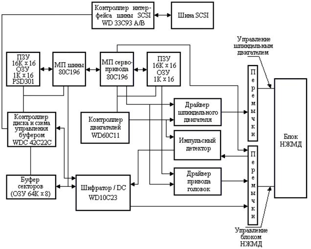
Fig. 4.6. HDD Management Scheme
The characteristics of some 3.5-inch hard drives are presented in table. 4.5. The table shows that the rotation speed V in the discs increased. In old hard drives, it was equal to 3,600 rpm, now it is most often equal to 7,200 rpm. Only in expensive HDDs with SCSI interface is it equal to 15,000 rpm. High speeds of disk rotation (7,200 rpm) and the movement of microscopic heads make it possible to obtain an average information access time of about 8 ms in the best HDD designs. The search time for the desired track depends on the initial position of the head and is the shortest if the head is on an adjacent track (track to track seek) t cd. The value of t cd for the best hard drives is 1 to 3 ms.
If the search is conducted randomly with an equally probable transition to any track, we can talk about the average access time (average seek) t cf. The capacity of new HDDs has significantly increased up to 20 GB or more. All HDDs are equipped with a cache buffer with a capacity of 2 MB and often 8 MB to speed up access to data. To improve the reliability of the HDD, the S.M.A.R.T. and special fault detection and correction methods.
| Table 4.5 HDD Features | |||||
| Firm Model | E disk / heads, GB | Vв, rpm | Cache buffer, Mb | t cf. ms | Interface |
| IBM DTLA-307020 | 20.5 2/3 | 7 200 | - | 8.5 | ATA / 100 |
| Maxtor DiamonMax80H8 | 81.9 4/8 | 5 400 | 9.0 | ATA / 100 | |
| Seagate Barracuda 180 ST1181677LW | 181.6 12/24 | 7 200 | 8.2 | Ultra 160 SCSI | |
| Western Digital WD200BB | 1/2 | 7 200 | 10.9 | ATA / 100 | |
| Fujitsu AL7LX MAM 3367NP | 36.7 4/8 | 15 000 | 3.5 | Ultra 320 SCSI ATA / 100 |
Technology S.M.A.R.T. was developed with the participation of the largest manufacturers of hard drives. To analyze the reliability of a hard disk, two groups of parameters are used: parameters of natural aging of the disk and current parameters.
The parameters of the first group include:
The number of engine revolutions during operation;
The number of movements of the read / write heads during operation.
The parameters of the second group include, for example, the following:
The distance between the read / write head and the work surface;
The speed of data exchange between disks and cache of the hard drive;
The number of reassigned bad sectors;
The speed of data search on disk.
All information S.M.A.R.T. recorded on special tracks. There are three versions (I, II, III) of S.M.A.R.T. technology. In S.M.A.R.T. III error prediction is carried out, surface scanning is carried out and in addition to I, II previous versions identifies and restores problem sectors. The BIOS allows the user to control the S.M.A.R.T. with the issuance of messages about the state of HDD. In this case, the MTBF hard drive mean time between failures, as the average statistical time between failures, is 500 thousand hours (at 40 - 50 thousand on / off cycles), which is an order of magnitude higher than other computer components.
IBM, Fujitsu, Quantum and other companies in HDD use glass and silicon wafers instead of aluminum to increase recording density and reliability because of their greater rigidity and purity. It also helps to reduce their weight. Also, many companies, such as IBM, are striving to reduce plate sizes (the smaller the plate, the less vibration) introducing new 27-millimeter standards. Company forecasts: an increase in the recording density of information will soon reach 300 Gbps per square meter. inch. The search for an alternative to magnetic disks continues. Among these innovations are organic magnetic films and cell-coated structures. Manufacturers believe that new technologies will supersede magnetic media.
The main disadvantages of magnetic disks are: aging of substrate materials, limiting the service life to 5 years; data loss from exposure to random electromagnetic fields; demagnetization during storage; sensitivity to shock and shaking.
Lecture 17: Optical drives
In 1972, Phllips demonstrated the Video Long Play system. It used the notch principle for recording data. It was the beginning of the development of CD- and later DVD-technology. The first standard optical disc drive CD-ROM, which includes a system for recording arbitrary digital data onto a CD, was developed in 1984 by Philips and Sony.
The mass CD-ROM of CD-ROM is available since 1988 as an information storage device with a capacity of 650 MB. This information corresponds to approximately 330,000 pages of text or 74 minutes of high-quality sound. At the moment there are several standards for CD-ROM - these are AAD, DDD, ADD. The letters of this abbreviation reflect the forms of the audio signal used to create the disk: the first - during the initial recording, the second - during processing and mixing, the third - the final master signal from which the disk is formed. “A” stands for Analog form, “D” stands for Digital. The master signal for a CD always exists only in digital form, so the third letter of the abbreviation is always "D". When recording and processing the signal in analog form, higher harmonics are preserved, but the noise level increases. When digitally processed, higher harmonics are forcibly cut off at half the sampling frequency.
CD-ROM compact discs are made with a thickness of 1.2 mm with an external diameter of 12 cm, with an internal hole of 15 mm from a polymeric material, which is coated on the underside with an aluminum alloy film (Fig. 4.7.). This film is a carrier of information, which after recording is protected by an additional layer of varnish. The top layer is inoperative, and labels and inscriptions are applied to it.
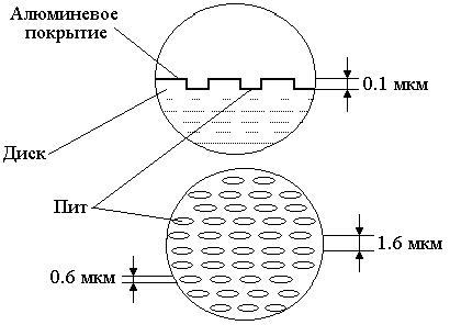
Fig. 4.7. Information layer on CD-ROM
The manufacture of disks takes place in several stages, including:
Recording by burning a laser beam of strokes ("serif", pit) for more than 1.5 hours on a master disk;
Receiving copies of hard metal matrices from the master disk;
Making copies of working disks by imprinting (stamping) with matrices.
As a result of the imprint, a spiral track of 0.6 μm width with a distance between the turns of 1.6 μm with grooves in the form of a dash of 0.12 μm with TPI \u003d 16,000 remains on the surface of the disk. The track starts near the central hole and ends 5 mm from the outer edge. The length of the spiral reaches 5 km. The principle of operation of the CD-ROM drive can be simplified by using fig. 4.8. The disk is rotated by the engine (D1), the control system of which provides a constant speed of movement of the track relative to the reader on any internal or external coil of the spiral. At the same time, the data reading speed for sound generation is strictly constant and equal to 75 blocks per second (150 Kb / s).
Each block contains 2,352 bytes. Of these, 2,048 are useful and 288 are control that are used to recover data (“failures” due to scratches, litter) up to 1,000 bits in length, 16 for synchronization. The control bits allow you to avoid errors with a probability of 10 -25. The position motor (D2) is designed to move a movable carriage (PC) with a mirror and a focusing lens to the desired turn of the spiral path according to the instructions of the built-in microprocessor.
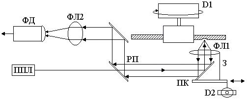
Fig. 4.8. How a CD-ROM Drive Works
A semiconductor laser (PPL) emits an infrared beam with a wavelength 4 times the stroke depth. This beam passes through a separation prism (RP), reflected from the mirror (3). Then, through the focusing lens (PL1), it is accurately directed to the track and reflected from it with different intensities depending on the stroke or plateau. Since the diameter of the light spot formed on the track by the laser beam is larger than the stroke size, damping interference arises between the reflected waves while the beam is reflected from the bottom of the stroke and the main surface, the intensity of the reflected beam decreases. In the absence of a stroke, the light spot is reflected equally, interference does not occur, the intensity of the reflected beam is preserved. The beam reflected from the track is sensed by a focusing lens (PL1) and, through RP and a focusing lens (PL2), is sensed by a photosensor (PD), which converts optical signals into electrical ones. The electrical signal taken from the PD when viewing the stroke in the CD is taken as a logical unit. The electrical signals are then transmitted to the sound card or to RAM. When transferred to a sound card (card), digital sequences are converted to analog signals, amplified and can be listened through headphones or speakers.
If the signals from the disk are arrays of digital data for the computer, then they are converted into parallel binary code by the built-in microprocessor, which can then transfer them to the segments of the RAM computer. Unlike sound recordings transferred to the sound card synchronously, digital data from a CD can be read into RAM with an increased speed of 4, 6, 8, 10. A drive and a CD-ROM having such speeds are called 4-10 speeds. They read data and transfer it to the system bus at a speed of 600, 900, 1200, 1500 Kb / s and have the best average access time to disk blocks of about 100 ms. At speeds above 5,000-6,000 rpm reliable reading becomes almost impossible, therefore, the latest models of 12-speed CD-ROMs and when reading data work in CAV mode (constant angular speed), rotating the disk with the highest possible speed. In this mode, the speed of data input from the disk varies depending on the position of the head, increasing from the beginning to the end of the disk. The speed specified in the passport (for example, 24x) is achieved only on the outer parts of the disk, and on the inside it drops to about 1200-1500 Kb / s. In drives with speeds of 20 and 24, the speed depends on the place of reading information from the CD and their average speed corresponds to about x14 with support for the BIOS mode PIO-4.
3.1. Rewritable optical drives
In addition to CD-ROM, CD-R (Recordable - recordable) and CD-RW (ReWritable - rewritable) standards are finding wider application. For one-time recording of the CD-R, so-called "discs" are used, which are a regular CD, in which the reflective layer is made primarily of gold or silver film. Between it and the polycarbonate base there is a recording layer of organic material (dye), which darkens when heated. During the recording process, the laser beam heats the selected points of the layer, which darken and cease to transmit light to the reflective layer, forming areas similar to "serifs".
CD-RW rewritable discs have a seven-layer structure that differs from cD-Rwhich contain five layers, as shown in fig. 4.9. CD-RW uses an intermediate layer of metal-plastic, which changes its phase state from amorphous to crystalline and vice versa under the influence of a beam. As a result, the transparency of the layer changes. The fixation of state changes occurs due to the fact that the material of the recording layer, when heated above the critical temperature, passes into the amorphous state and remains in it after cooling, and when heated to a temperature well below the critical temperature, it restores the crystalline state. Such discs can withstand thousands to tens of thousands of rewriting cycles. However, their reflectivity is significantly lower than single CDs, which makes them difficult to read in conventional drives. To read CD-RW, you need a drive with automatic gain control of the photodetector (Auto Gain Control), although some conventional CD-ROM drives and home players can read them along with regular drives. The ability of the drive to read CD-RW is called Multiread.
A rewritable disc can have the same structure and file system as a CD-R, or a special one can be organized on it file system UDF, which allows you to dynamically create and destroy individual files on disk.
|
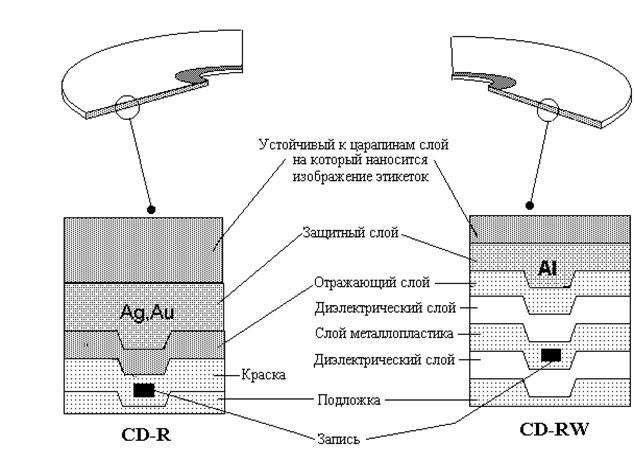
Figure 4.9. CD-R and CD-RW recording structure
3.2. Digital universal disc
The standard for DVD was developed in 1995 jointly by several companies (Hitachi, JVC, Philips, etc.). Not only video, but also audio and any other data can be recorded on DVDs, so it is more often used as a digital universal disc (Versatile). The main difference between DVDs and CDs is the difference in the amount of information. DVD capacity is increased in several ways:
Firstly, a laser with a shorter wavelength is used to read DVDs than to read CDs, which significantly increased the recording density;
Secondly, the standard provides for two-layer discs for which data is recorded on one side in two layers. In this case, one layer is translucent, which allows reading through the first layer.
With an increase in the recording density and a decrease in the wavelength of the readout laser, the requirement for the thickness of the protective plastic layer has changed; for DVDs, it is only 0.6 mm, in contrast to 1.2 mm used in CDs. However, in order to preserve the usual dimensions of the disc and to avoid excessive fragility of DVD-ROM drives, they are filled with plastic on both sides, so that the final disc thickness is the same 1.2 mm. This made it possible to record data on both sides of DVDs and thus double their capacity. The main types DVD discs the following:
DVD-5 (4.7 GB) with data recording in one layer on one side;
DVD-9 (8.5 GB) with data recording in two layers on one side;
DVD-10 (9.4 GB) with data recording on two sides on one layer;
DVD-14 (13.24 GB) with data recording in two layers on one side, one layer on the other;
DVD-18 (17 GB) with data recording on two sides in two layers.
The characteristics of Samsung optical discs are presented in table. 4.6.
Since a DVD-ROM is often used for transferring graphics, multimedia and watching videos, for high-quality reproduction of pictures (720x576 pixels with a color depth of 24 bits, in the European PAL standard) a data transfer speed of 30 Mb / s is required, and to watch a movie you need a disk capacity of about 100 GB In order to reduce the requirements for data transfer rate (V ol) and increase the amount of data, the MPEG-2 compression algorithm is used. This allows you to reduce the data rate to 3 - 4 Mb / s. When compressed, it is deleted to reduce up to 97% of redundant information with virtually no damage to picture quality. In order to recover data read from a DVD-ROM, the information must be decoded, i.e. Recover redundant information deleted during compression. This can be done either programmatically without the use of specialized hardware, or using a hardware DVD decoder.
For DVD-ROMs, as well as for CD-ROMs, there are rewriting formats - these are DVD-RAM and DVD + RW with a capacity of up to 2.6 GB and up to 3 GB, respectively, but both of these formats are incompatible with each other. The principle of dubbing is the same as that of CD technology, but the recording is done in layers and the density on the disc is higher.
Currently, several interfaces are used for CD and DVD drives, these are EIDE, ATAPI, SCSI, as well as USB.
| Table 4.6 Characteristics of optical drives | ||
| Parameters | CD-RW (SW-208) | DVD-ROM (SD-612) |
| CD write speed (Kb / s) | 1200 (8x) | - |
| CD rewrite speed (Kb / s) | 600 (4x) | - |
| CD read speed (Kb / s) | 4800 (32x) | 6000 (40x) |
| DVD read speed (Kb / s) | - | 16200 (12x) |
| Interface | Eide | Eide |
| Buffer size (kb) | ||
| Audio Output Power (W) | 0,7 | 0,7 |
| CD-R Recording 650 (Mb) | + | - |
| Burn CD-RW 700/650/550 (Mb) | + | - |
3.3. Next Generation Optical Drives
In the new generation of drives, the so-called fluorescent discs (FM discs), the principle of "photochromism" is used. This phenomenon is manifested in organic material containing photochromic particles, which under the influence of a laser beam of a certain wavelength emit a fluorescent glow. Initially, photochrome does not have fluorescent properties. The recording is carried out under the influence of a high-power laser in the areas where the photochemical reaction is initiated, as a result of which the fluorescent properties begin to appear. When reading photochromic particles in areas irradiated with a laser, they are again excited by a laser of lower power and begin to fluoresce. This glow is detected by the photodetector and is taken as the value "1". The feature of the FM-disk is reflected in the characteristics of the drive:
Layering, transparency and uniformity;
Low signal loss when passing through several layers;
The fluorescent glow of the elements is "transparent" for all layers of the disk;
Less sensitivity than CD / DVD to various disadvantages of readers;
Fluorescence from any layer is not coherent; interference, which is present in CD / DVD technologies, is excluded;
Fluorescent technology is compatible with CD and DVD data distribution formats on each layer.
Comparative characteristics 50 GB of a fluorescent disk are presented in tab. 4.7.
From the table. Figure 4.7 shows that the FM disc allows you to store and use more data than CDs or DVDs, and maybe in the near future FM discs will replace other optical drives.
Lecture 17: Microprocessor buses: systems and exchange cycles
The most important thing that a developer of microprocessor systems should know is the principles of organizing the exchange of information on the buses of such systems. Without this, it is impossible to develop the hardware of the system, and without the hardware, no software will work.
For more than 30 years since the first microprocessors appeared, certain exchange rules have been developed, which are followed by the developers of new microprocessor systems. These rules are not too complicated, but it is necessary to know and strictly observe them for successful work. As practice has shown, the principles of bus exchange are much more important than the features of specific microprocessors. Standard system backbones live much longer than a particular processor. Developers of new processors are guided by the existing standards of the highway. Moreover, some systems based on completely different processors use the same system backbone. That is, the highway is the most important system-forming factor in microprocessor systems.
Information exchange in microprocessor systems occurs in information exchange cycles. An information exchange cycle is understood to mean a time interval during which one elementary exchange operation is performed on the bus. For example, forwarding a data code from a processor to memory, or forwarding a data code from an input / output device to a processor. Within the same cycle, several data codes can be transmitted, even an entire array of data, but this is less common.
Information exchange cycles are divided into two main types:
· A recording (output) cycle in which the processor writes (outputs) information;
· A read (input) cycle in which the processor reads (enters) information.
In some microprocessor systems, there is also a read-modify-write or input-pause-output cycle. In these cycles, the processor first reads the information from the memory or I / O device, then somehow converts it and writes it back to the same address. For example, a processor can read code from a memory location, increase it by one, and write it back to the same memory location. The presence or absence of this type of cycle is associated with the features of the processor used.
A special place is taken by direct memory access cycles (if the DAP mode is provided in the system) and interrupt request and provision cycles (if there are interruptions in the system). When in the future we will talk about such cycles, this will be specifically stipulated.
During each cycle, the devices involved in the exchange of information transmit information and control signals to each other in a strictly established order or, as they say, in accordance with the adopted information exchange protocol.
The duration of the exchange cycle can be constant or variable, but it always includes several periods of the system clock signal. That is, even in the ideal case, the frequency of reading information by the processor and the frequency of recording information are several times less than the clock frequency of the system.
Reading command codes from the system memory is also done using read cycles. Therefore, in the case of a single-bus architecture, cycles of reading commands and cycles of transfer (reading and writing) of data alternate on the system bus, but the exchange protocols remain unchanged regardless of whether the data or commands are transmitted. In the case of a two-bus architecture, the cycles for reading commands and writing or reading data are separated on different buses and can be performed simultaneously.
Hard disk drives (HDD, hard drives, Hard Disk Drive - HDD) are devices designed for long-term storage of information. As hard disk drives, Winchester drives are widely used in PCs. The term “Winchester” is the jargon name of the first 16 Kbyte hard drive model (IBM, 1973), which had 30 tracks of 30 sectors each, which accidentally coincided with the 30/30 caliber of a famous Winchester hunting rifle. In these drives, one or more hard drives made of aluminum or ceramic alloys and coated with ferro-varnish, together with a block of magnetic read-write heads are placed in a hermetically sealed enclosure. Under the disks there is an engine that provides rotation of the disks, and on the left and right there is a rotary positioner with a rocker controlling the movement of the magnetic heads in a spiral arc for installation on the desired cylinder. The capacity of hard drives due to the extremely tight recording performed by magnetoresistive heads in such hermetic structures reaches several tens of gigabytes; their speed is also very high: access time from 5 ms, transfer (access speed) up to 6 GB / s. Magnetoresistive technologies provide extremely high recording density, allowing you to place 2-3 GB of data on one plate (disk). The appearance of heads with a giant magnetoresistive effect (GMR - Giant Magnetic Resistance) further increased the recording density - the possible capacity of one plate increased to 6.4 GB.
HDDs are very diverse. The diameter of the disc is most often 3.5 inches (89 mm). The most common drive enclosure height: 25 mm for desktops, 41 mm for servers, 12 mm for laptops, and others. External disc tracks are longer than internal. Therefore, modern hard drives use the zone recording method. In this case, the entire disk space is divided into several zones, and more data is placed in the external zones of the sectors than in the internal ones. This, in particular, made it possible to increase the capacity of hard drives by about 30%.
The appearance of the NMR with the cover removed is shown in Fig. .
Fig. __. HDD with cover removed
There are two main modes of data exchange between HDD and OP:
Programmed Input / Output (PIO - programmable input-output);
Direct Memory Access (DMA - direct memory access).
Pio - This is a mode in which data is moved between a peripheral device (hard disk) and RAM with the participation of the central processor. The fastest PIO provides 16.6 MB / s. PIO mode is rarely used in modern PCs, as the processor is heavily loaded.
DMA - this is a mode in which the hard drive communicates directly with RAM without the participation of the central processor, intercepting bus control. Transfer - up to 66 MB.
With interfaces (on peripheral buses), SCSI can achieve a higher transfer rate of 80 MB / s, while up to 15 drives can be connected to one interface controller. A technology that uses fiber-optic communication channels for SCSI hard drives provides a transfer of 200 MB / s and the ability to connect up to 256 devices (it is used, of course, not in a PC, but in large systems and in disk arrays - RAID).
The access time to information on the disk is directly related to the speed of rotation of the disks. The standard rotation speeds for the IDE interface are 3600, 4500, 5400 and 7200 rpm; SCSI uses speeds of up to 10,000 and even up to 12,000 rpm. At a speed of 10,000 rpm, the average access time is 5.5 ms. To increase the speed of data exchange between the processor and the hard disk drives, cache should be cached. The cache memory for disks has the same functionality as the cache for main memory, that is, it serves as a high-speed buffer for short-term storage of information read or written to disk. The cache memory can be built into the drive, or it can be created programmatically (for example, by the Microsoft Smartdrive driver) in the RAM. The disk cache’s capacity is usually 2 MB, and the processor’s cache data exchange rate reaches 100 MB / s.
In order to get on magnetic carrier the disk structure, which includes tracks and sectors, a procedure called physical or low-level formatting should be performed on it. During this procedure, the controller writes service information to the media, which determines the layout of the disk cylinders into sectors and numbers them. Low-level formatting also provides for marking defective sectors to prevent access to them during disk operation.
The PC usually has one, less often several hard disk drives. However, by software, one physical disk can be divided into several "logical" disks; thereby simulating several NMD on a single drive.
Most modern drives have their own cache memory with a capacity of 2 to 8 MB.
ExternalHDD belong to the category of portable.
Recently, portable drives (they are also called external, mobile, removable, and their portable options - pocket - Pocket HDD) are widespread. Portable hard drives are powered either from the keyboard or via the USB bus (a possible option is via the PS / 2 port).
Portable hard drives very diverse: from conventional HDDs in separate cases to rapidly growing solid-state drives. Form factor more often - 2.5 inches, capacity 1-60 GB.
Optical drives CD-R, CD-RW, DVD-R, DVD-RW and DVD-RAM also allow you to transfer large amounts of data from one computer to another. Their media provide the transfer of large amounts of data from one computer to another. In addition, due to the relatively high performance, these drives can be used for the same purposes as conventional stationary hard drives. Such devices can also be used to solve information backup tasks.
Sometimes HDDs with removable disk packages and Zip-type HDDs are called Bernoulli drives, because in these drives to minimize and control the gap between the magnetic head and the carrier - magnetic disk - Bernoulli’s law is used: the pressure on the surface of a body created by the flow of a fluid or gas moving along it depends on the speed of this flow and decreases with increasing this speed. Magnetic heads are located above the surface of elastic disks: when the disks are stationary, they sag slightly and move away from the heads under the influence of their weight, and when the disks rotate quickly under the influence of the created vacuum, they are attracted to the heads almost closely, but without touching them. This provides a minimum dispersion of the magnetic flux of the head and allows you to increase the recording density of information on the disk.