DIY Arduino
Well, it's time to master the duino platform on your own. First, let's figure out what we might need. For starters, it would not be bad to decide on the basis of what we will make our copy of the debug board. To simplify the initial task, I suggest using a USB-(UART)TTL adapter to upload sketches. This will make our life much easier. personally, I will use a cheap adapter ordered from a now defunct online store, but it still works.
When building our Duino, we will try to use the minimum number of elements. As we develop, we will add the necessary components.
For reference, we will find diagrams of various platforms on the official website:
In my opinion, the schemes are good, but it would be nice to see the already proven implementations of "homemade", I really liked 3 options:
We will build a minimum harness for our device. At the first stage of the details, a minimum is needed:
Actually the atmega328P MK itself (in my case, although 168 and 8 can also be used)
Quartz 16 MHz
Capacitor 22pF x 2pcs.
10k resistor
Reset button (any, by the way, not a required element)
That's basically all that is minimally necessary for the operation of the microcontroller. I propose to illustrate and design all our works in a very good Fritzing program:

Well, let's see why these elements are needed. The button allows you to restart the microcontroller, resistor R1 is a pull-up resistor for the button. Crystal, C1 and C2 are the external clock generator for the controller.
This is a necessary and sufficient binding, but personally I strongly recommend that you install a 100nF ceramic capacitor in parallel with the main power supply of the microcircuit.

Well, our minimal Duino is ready. In order to make it more convenient to use this debugging tool, I suggest sticking a hint with the "atmega" pinout on the case. My version is implemented in Corel Draw:
First, let's assemble the circuit of our Duino on a solderless breadboard, here's what I got:

To upload sketches, we will use a USB - TTL adapter, in the photo is my already pretty shabby adapter based on the CP2102 chip:

But before uploading the sketches, it is necessary to upload the bootloader to the MK, otherwise, it will not "understand" what we want from it. There are many ways, but we will use the simplest. Using the wonderful USBasp programmer:

First, let's connect our Duino to the programmer, it's very simple, just connect the programmer's contacts to the Duino:
GND - ground (22 feet)
MOSI - MOSI (d11)
5V - power supply "+" (7 leg)
Then Arduino IDE-> Tools -> "Burn bootloader":

During the bootloader recording process, you will have to wait about 2 minutes. After that, various "warnings" may fall out to us, such as "can not set SCK period" - do not get scared and move on.
Well, here we are ready to record the "Blink" test sketch into our newly minted Duino, but there is one point, and I would like to dwell on it. As we have already said, a serial port is used to record sketches, but in the "normal" life of the MK these are digital ports 0 and 1. Everything is very simple, we have already uploaded the bootloader, it initializes the recording new firmware when turned on for a few seconds, after that the Duino starts executing the program that is stored in its memory.
To put the Duino into the "receive" mode, you need to restart the MK, for this we made a special button, but you need to press it strictly at a certain moment, this is not at all suitable for us. Fortunately, there is a special "RST" pin on the adapters, which is enough to connect to 1 leg of the MK, in order to automatically reboot the Duino before loading the sketch. The connection is very simple, (adapter - Duino):
GND - ground (22 feet)
RXD - connect to TXD (3 leg)
TXD - connect to KXD (2 legs)
5V - power supply "+" (7 leg)
As you noticed, the receive / transmit contacts are connected crosswise. And everything would be fine, but there is one "but": there are a huge number of adapters, and to automatically reset the MK, you need to introduce a 100pF capacitor into the RST circuit break - reset (1 leg). Some adapters have it, and some don't. Here you only need to check, in my copy there was no built-in capacitor. As a result, the scheme is a little "complicated":

Well, now you can load the sketch into Duino's memory and try to do some experiments =) (LEDs are added to the photo - indicators of sketch loading):

Arduino is a versatile DIY platform for microcontrollers. There are many shields (expansion boards) and sensors for it. This diversity allows you to make a number of interesting projects aimed at improving your life and increasing its comfort. The areas of application of the board are endless: automation, security systems, systems for collecting and analyzing data, and so on.
From this article you will learn what you can do interesting things on Arduino. Which projects will be spectacular, and which ones will be useful.
What can be done with Arduino
robot vacuum cleaner
Cleaning the apartment is a routine and unattractive task, especially since it takes time. You can save it if some of the household chores are assigned to the robot. This robot was assembled by an electronics engineer from Sochi - Dmitry Ivanov. Structurally, it turned out to be of sufficient quality and is not inferior in efficiency.

To assemble it you will need:
1. Arduino Pro-mini, or any other similar and suitable size...
2. USB to TTL adapter if you are using Pro mini. If you chose the Arduino Nano, then you don't need it. It is already installed on the board.
3. L298N driver is needed to control and reverse DC motors.
4. Small engines with gears and wheels.
5. 6 IR sensors.
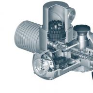
6. Engine for the turbine (larger).
7. The turbine itself, or rather the impeller from the vacuum cleaner.
8. Motor for brushes (small).
9. 2 collision sensors.
10. 4 x 18650 batteries.
11. 2 DC-DC converters (boost and step-down).
13. Controller for operation (charge and discharge) of batteries.
The control system looks like this:

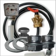
And here is the power system:

Such cleaners are evolving, factory-made models have complex intelligent algorithms, but you can try to make your own design that will not be inferior in quality to expensive counterparts.
Able to produce a luminous flux of any color, they usually use LEDs in the body of which there are three crystals glowing in different colors. They are sold for control, their essence lies in regulating the current supplied to each of the colors led strip, therefore - the intensity of the glow of each of the three colors is regulated (separately).
You can make your own RGB controller on Arduino, even more, this project implements control via Bluetooth.

The photo shows an example of using a single RGB LED. To control the tape, you will need an additional 12V power supply, then they will control the gates field effect transistors included in the chain. The gate charge current is limited by 10 kΩ resistors, they are installed between the Arduino pin and the gate, in series with it.

With a microcontroller, you can Universal remote remote control controlled from a mobile phone.

For this you will need:
Arduino of any model;
IR receiver TSOP1138;
IR LED;
Bluetooth module HC-05 or HC-06.
The project can read codes from factory remotes and store their values. After that, you can control this homemade product via Bluetooth.
The webcam is mounted on a rotary mechanism. It is connected to a computer with installed software. It is based on the computer vision library - OpenCV (Open Source Computer Vision Library), after the program detects a face, the coordinates of its movement are transmitted via a USB cable.

The Arduino gives a command to the drive of the rotary mechanism and positions the camera lens. A pair of servos are used to move the camera.
The video shows the operation of this device.
Watch your animals!
The idea is this - find out where your animal walks, this can be of interest to scientific research and just for fun. To do this, you need to use a GPS tracker. But to store location data on some drive.

At the same time, the dimensions of the device play a decisive role here, since the animal should not feel discomfort from it. To record data, you can use it to work with Micro-SD memory cards.
Below is a diagram of the original version of the device.

The original version of the project used the TinyDuino board and shields for it. If you can't find one, you can use small Arduinos: mini, micro, nano.
For power, a Li-ion element of small capacity was used. The small battery lasts for about 6 hours. The author ended up fitting everything in a cut-off tic-tac jar. It is worth noting that the GPS antenna must point upwards in order to receive valid sensor readings.
Combination lock breaker
To crack code locks with Arduino, you will need a servo and stepper motor. This project was developed by hacker Samy Kamkar. This is a rather complex project. The operation of this device is shown in the video, where the author tells all the details.
Of course, such a device is hardly suitable for practical use, but this is an excellent demonstration.
Arduino in music
This is more likely not a project, but a small demonstration of how this platform has been used by musicians.
Drum machine on Arduino. It is noteworthy that this is not an ordinary enumeration of recorded samples, but, in principle, sound generation using "iron" devices.

Detail ratings:
NPN-type transistor, for example 2n3904 - 1 pc.
Resistor 1 kOhm (R2, R4, R5) - 3 pcs.
330 Ohm (R6) - 1 pc.
10 kOhm (R1) - 1 pc.
100 kOhm (R3) - 1 pc.
Electrolytic capacitor 3.3 uF - 1 pc.
For the project to work, you will need to connect the library for fast expansion into a Fourier series.
It is quite simple and interesting project from the category of "you can brag to your friends."
3 robot projects
Robotics is one of the most interesting areas for geeks and just those who like to do something unusual with their own hands, I decided to make a selection of several interesting projects.
BEAM-robot on Arduino
To assemble a four-legged walking robot, you will need:
Servo motors are needed to move the legs, for example, Tower Hobbies TS-53;
A piece of copper wire of medium thickness (to withstand the weight of the structure and not bend, but not too thick, because it does not make sense);
Microcontroller - AVR ATMega 8 or Arduino board of any model;
For the chassis in the project, it is indicated that the Sintra Frame was used. It is something like plastic, it bends into any shape when heated.
As a result you will get:

It is noteworthy that this robot does not drive, but walks, can step over and go to elevations up to 1 cm.
For some reason, this project reminded me of a robot from the Wall-e cartoon. Its feature is the use for charging batteries. It moves like a car, on 4 wheels.

Its component parts:
Jumpers mom-dad;
Solar panel with an output voltage of 6V;
As a donor of wheels, engines and other parts - a radio-controlled car;
Two continuous rotation servos;
Two conventional servos (180 degrees);
Holder for AA batteries and for the "crown";
Collision sensor;
LEDs, photoresistors, 10 kΩ fixed resistors - 4 in total;
Diode 1n4001.
Plastic bottle of suitable size;
Here is the basis - the Arduino board with a proto-shield.

This is how spare parts from - wheels look like.

The design is almost complete, the sensors are installed.

The essence of the work of the robot is that it goes to the light. Abundance he needs to navigate.

This is more of a CNC machine than a robot, but the project is very entertaining. It is a 2 axis drawing machine. Here is a list of the main components of which it consists:
(DVD) CD drives - 2 pcs;
2 drivers for stepper motors A498;
servo MG90S;
Arduino Uno;
Power supply 12V;
Ballpoint pen, and other design elements.
From the drive optical discs blocks are used stepper motor and a guide rod that positioned the optical head. From these blocks, the engine, shaft and carriage are removed.

You won’t be able to control a stepper motor without additional equipment, therefore, special driver boards are used, it is better if a motor radiator is installed on them at the time of starting or changing the direction of rotation.
The complete assembly and operation process is shown in this video.
See also top 16 Arduino projects from AlexGyver:
Conclusion
This article is just a small drop of what you can do on this popular platform. In fact, it all depends on your imagination and the task that you set for yourself.
Microcontrollers are an excellent basis for a large number devices. In essence, they resemble a computer: read-only memory; RAM; computing core; clock frequency.
Among the many families and types of MK, beginners often choose AVR Atmega controllers. However, the programming language can seem complicated, so a teacher from Italy decided to develop a simple and convenient board for learning.
The Arduino ATmega8 was born, on the basis of which you can assemble a very convenient and simple device.
With these boards from Arduino, you get a number of advantages:
- ready divorced printed circuit board with all necessary components and connectors;
- Atmega microcontrollers;
- the ability to program without programmers - via the USB port;
- powered by any source of 5-20 volts;
- a simple programming language and the ability to use pure C AVR without reworking the board and firmware.
- ATmega8 frequency: 0-16MHz
- ATmega8 voltage: 5V
- ATmega8L frequency: 0-8MHz
- Frequency ATmega8A: 0-16MHz
In reality, almost all microcontrollers at an operating voltage of 5 volts operate at a frequency of 16 megahertz, if an external quartz resonator is involved. If we take the internal generator, then the frequencies will be: 8, 4, 2 and 1 MHz.
Arduino ATmega8 Pinout
Below is the atmega8 pinout, which can also be found on the official website of the manufacturer:

Adding ATmega devices
There is one caveat to working with this chip - we need to make some changes to one file so that we can continue to program the Arduino ATmega8 microcontrollers.
Make the following changes to the file hardware/arduino/boards.txt:
atmega8o.name=ATmega8 (optiboot 16MHz ext) atmega8o.upload.protocol=arduino atmega8o.upload.maximum_size=7680 atmega8o.upload.speed=115200 atmega8o.bootloader.low_fuses=0xbf atmega8o.bootloader.high_fuses=0xdc atmega8o.bootloader.path =optiboot50 atmega8o.bootloader.file=optiboot_atmega8.hex atmega8o.bootloader.unlock_bits=0x3F atmega8o.bootloader.lock_bits=0x0F atmega8o.build.mcu=atmega8 atmega8o.build.f_cpu=16000000L atmega8o.build.core=arduino:arduino atmega8 o. build.variant=arduino:standard ########################################## ################### a8_8MHz.name=ATmega8 (optiboot 8 MHz int) a8_8MHz.upload.protocol=arduino a8_8MHz.upload.maximum_size=7680 a8_8MHz.upload.speed= 115200 a8_8MHz.bootloader.low_fuses=0xa4 a8_8MHz.bootloader.high_fuses=0xdc a8_8MHz.bootloader.path=optiboot a8_8MHz.bootloader.file=a8_8MHz_a4_dc.hex a8_8MHz.build.mcu=atmega8 a8_8MHz.build.f_cpu=8000 000L a8_8MHz.build.core =arduino a8_8MHz.build.variant=standard ######################################## ##################### a8_1MHz.name=ATmega8 (optiboot 1 MHz int) a8_1MHz.upload.protocol=arduino a8_1MHz.upload.maximum_size=7680 a8_1MHz.upload. speed=9600 a8_1MHz.bootloader.low_fuses=0xa1 a8_1MHz.bootloader.high_fuses=0xdc a8_1MHz.bootloader.path=optiboot a8_1MHz.bootloader.file=a8_1MHz_a1_dc.hex a8_1MHz.build.mcu=atmega8 a8_1MHz.build.f_cpu=10000 00L a8_1MHz.build .core=arduino a8_1MHz.build.variant=standard ###################################### ####################### a8noboot_8MHz.name=ATmega8 (no boot 8 MHz int) a8noboot_8MHz.upload.maximum_size=8192 a8noboot_8MHz.bootloader.low_fuses=0xa4 a8noboot_8MHz .bootloader.high_fuses=0xdc a8noboot_8MHz.build.mcu=atmega8 a8noboot_8MHz.build.f_cpu=8000000L a8noboot_8MHz.build.core=arduino a8noboot_8MHz.build.variant=standard
Thus, if we go to the menu Service → Fee, then we will see the devices:
- ATmega8 (optiboot 16MHz ext)
- ATmega8 (optiboot 8 MHz int)
- ATmega8 (optiboot 1MHz int)
- ATmega8 (no boot 8 MHz int)
Arduino boards
The Arduino comes in many varieties; the main thing that unites the boards is the concept of the finished product. You do not need to etch the board and solder all its components, you get a ready-to-use product. You can assemble any device without using a soldering iron. All connections in the basic version are made using a breadboard and jumpers.
The heart of the board is a microcontroller of the AVR family. Initially, the atmega8 microcontroller was used, but its capabilities are not unlimited, and the board has been upgraded and changed. The standard board that is most common among hobbyists is the UNO version board, there are many variations of it, and its size is comparable to a credit card.
The board is a complete analogue of a larger brother, but in much smaller sizes, the arduino atmega168 version was the most popular and inexpensive, but it was replaced by another model - arduino atmega328, the cost of which is similar, but the possibilities are greater.
The next important part is the printed circuit board. Diluted and soldered at the factory, avoids problems with its creation, etching and soldering. The quality of the board depends on the manufacturer of a particular instance, but, in general, it is at a high level. The board is powered by a pair of linear stabilizers, such as L7805, or other LDO voltage regulators.
The terminal block is a great way to make a secure plug-in connection and quickly make changes to the layout of your device prototypes. For those who lack standard connectors, there are larger and more powerful boards, for example, on the atmega2560, which has fifty ports available for working with peripherals.

The photo shows the board. Based on it, you can assemble a rather complex robot, a smart home system or an arduino 3d printer.
You should not think that the younger versions are weak, for example, the atmega328 microcontroller, on which the Uno, nano, mini and others models are built, has twice more memory compared to the 168 model - 2 kb of RAM and 32 kb of Flash memory. This allows more complex programs to be written to the microcontroller's memory.
Arduino ATmega based projects
The microcontroller in modern electronics is the basis for any device, from a simple LED flasher to universal measuring instruments and even production automation tools.
Example 1
You can make a tester with 11 functions on the atmega32 microcontroller.

The device has an extremely a simple circuit, which uses a little over a dozen parts. However, you get a fully functional device that can be used to measure. Here is a short list of its features:
- Continuity of the circuit with the ability to measure the voltage drop at the diode junction.
- Ohmmeter.
- Capacity meter.
- Measurement of capacitor resistance or ESR.
- Definition of inductance.
- Pulse counting capability.
- Frequency measurement - useful in diagnostics, for example, to check the PWM of a power supply.
- The pulse generator is also useful in repairs.
- The logic analyzer will allow you to view the contents of the digital signal bursts.
- Zener tester.
Example 2
It will be useful for radio amateurs to have quality equipment, but the station is expensive. It is possible to assemble a soldering station with your own hands, for this you need an Arduino board, which includes an atmega328 microcontroller.

Example 3
For advanced radio amateurs, it is possible to assemble a more than budget oscilloscope. We will publish this lesson in future articles.

For this you will need:
- Arduino uno or atmega
- Tft display 5 inch.
- A small set of straps.
Or its simplified analogue on the Nano board and display from nokia 5110.
Such an oscilloscope probe will be useful for an auto electrician and an electronic equipment repairman.

Example 4
It happens that the controlled modules are remote from each other or the capabilities of one arduino are not enough - then you can assemble a whole microcontroller system. To ensure communication between two microcontrollers, it is worth using the RS 485 standard.

The photo shows an example of the implementation of such a system and data entry from the keyboard.
Color music on the Arduino ATmega8 microcontroller
For a school disco, you can assemble a CMU for 6 channels.

Transistors VT1-VT6 need to be selected based on the power of your LEDs. These are power components - they are needed because the power of the microcontroller is not enough to run powerful lamps or LEDs.
If you want to switch the mains voltage and collect color music on incandescent lamps, you need to install triacs and a driver instead. Supplement each channel of the DMU with the following construction:

DIY Arduino
Atmega2560 is a powerful and advanced controller, but it is easier and faster to assemble the first board on atmega8 or 168.

The left side of the diagram is a USB communication module, in other words, a USB-UART / TTL converter. It, together with the strapping, can be thrown out of the circuit to save space, assembled on a separate board and connected only for firmware. It is needed to convert signal levels.
DA1 is the L7805 voltage regulator. As a basis, you can use a number of avr chips that you find, for example, series, arduino atmega32 or build arduino atmega16. To do this, you need to use different loaders, but for each of the MK you need to find your own.
You can do it even easier and assemble everything on a solderless breadboard, as shown here, using the example of the 328th atmega.

Microcontrollers are simple and fun - you can do a lot of nice and interesting things, or even become an outstanding inventor, without having any education or knowledge of low-level languages. Arduino is a step into electronics from scratch, which allows you to move on to serious projects and the study of complex languages, such as C avr and others.
In my opinion, it makes no sense to collect UNO in the form in which it is presented in the original. I always use this one:
Here everything is generally without crap - just 1 microcircuit and quartz. True, unlike the Arduino UNO, there is no power protection and USB - accordingly, uploading sketches is a bit more complicated. Let's figure it out.
Copy Arduino uno - power
Firstly, in this circuit there is only one voltage - the one that feeds the microcontroller. The arduino uno has a stabilizer - you give it 5 volts, it also gives out 3.3 to the adjacent pin. In all my practice, I have never needed both 5 and 3.3 volts at once in one circuit. That is, either 5 or 3.3 is used, but never both. All devices, screens and sensors, designed for 3.3, always stuck 5 volts and everything worked. Naturally, you need to read the datasheet (documentation) for these same sensors, maybe you have something mega-sensitive to the input voltage and it really needs 3.3 volts. Then you can put a voltage regulator and lower it to 3.3 volts. As usual, there are a couple of ways:

In general, there are a lot of perverted schemes with nutrition, but these are the main approaches.
USB for our UNO
There are also two approaches here. There is this thing called ISP: 
This is such a connector)) In order to make our new UNO work, we need a microcontroller. If you just go to the store and buy an Atmega326, you will certainly do well, but it will not work right away - you need to sew the Arduino bootloader into it. strangely enough, a second Arduino is needed for this. Already working Xs where do you get it, buy it in China or ask a friend to drive it. Basically, any will do. Let's call it conditionally programmer. And you need to connect like this:
pin name: not-mega: mega(1280 and 2560) reset: 10:53 MOSI: 11:51 MISO: 12:50 SCK: 13:52
pin name : not - mega : mega (1280 and 2560 ) reset: 10:53 MOSI: 11:51 MISO: 12:50 SCK: 13:52 |
If you got it somewhere as an Arduino Mega programmer, then use the last column to connect. If other arduins serve as a programmer, then the second one. The first column shows the legs of your new purchased atmega. Next, in the working arduino (programmer), we fill in the sketch from the samples with the name ArduinoISP:

And here we have two options:
- You can flash the bootloader and then in the future our microcontroller can be flashed through the Serial port and we no longer need the second arduin programmer.
- Or you can immediately flash our sketch through the programmer without a bootloader - and then after launch everything will work faster for a couple of seconds. This is done using the menu file –> upload through the programmer
If everything is clear with the second option .. Then the first one requires clarification. Click Tools - Programmer - Arduino. And then Tools - Burn bootloader.

After that, we turn off the Arduino and now we need a USB to ttl serial Converter. After we got it, we need to connect it to reset, d0 (rx), d1 (tx) of our newly flashed atmega.


The essence is the same, just do not forget to add a resistor and a capacitor to reset (see the first option).
After that, everything will be flashed in the same way as a regular arduino.
From a practical point of view, it’s easier to buy a ready-made board and not bother, but the skills gained in the manufacture of this crafts, may be useful in the future.

Step 1: Required radio parts and tools
Any manufacturing process homemade begins with the preparation of the material and technical base.

Radio components:
- ATmega328;
- 2 electrolytic capacitors with a capacity of 10 uf (micro farad);
- 2 capacitors in a round ceramic case with a capacity of 22 pf (picofarad);
- voltage regulator L7805;
- quartz resonator 16 MHz;
- clock button;
- LEDs;
- socket for a microcircuit;
- voltage regulator LM1117T-3.3 (optional);
- 2 tantalum capacitors with a capacity of 10 uf (microfarads) (optional).
Tools:
- soldering iron;
- Multimeter.
Step 2: Description

After we purchased all the radio components, it's time to install, but before that I need to say a few words about the atmega328. There are two types of chips: with boot-loader (bootloader, aka bootloader) and without it. The difference in the price of chips is not significant, but if you buy a "mikruha" with a bootloader, you can skip a few steps from this article. If you buy without a bootloader, then you must follow exactly everything that is described in the following steps.
The bootloader is required to upload code from the Arduino IDE to the chip.
Step 3: Download the "bootloader"

For this step, you will need an Arduino UNO board. Following the scheme, we solder the radio components to the circuit board. At this stage, there is no need to include voltage regulators in the circuit, as the Arduino will provide the necessary voltage.
Let's set up the Arduino UNO board as an ISP. This must be done in order for the board to flash the ATmega microcontroller, and not itself. Do not connect the ATmega while the code is being downloaded.

- Connect Arduino to PC;
- Open the Arduino IDE;
- Open > Examples > Arduino ISP;
- Let's download the firmware.
Step 4:

After all the elements of the circuit are connected together, open the IDE.
- Select Arduino328 from Tools > Board
- Select Arduino as ISP from Tools > Programmer
- Choose Burn Bootloader
After a successful write, you will get "Done burning bootloader".
Step 5: Adding a 5V Regulator

After flashing the bootloader, we will complete the manufacture of the board. The L7805 voltage regulator is an important part of the circuit. The pinout is as follows (look at the front side): the leftmost leg is the entrance, the central leg is the ground, and the rightmost leg is the exit.

Following the diagram, we will connect the voltage regulator to the arduino.

Step 6: 3.3V voltage regulator

This step is optional. The regulator is only used to power external shields/modules that require 3.3V.

Step 7: First Firmware

Once we're done on the side, it's time to upload the first code. For firmware, we will remove the native ATmega 328 microcontroller from the UNO board and replace it with a new mikruha. As soon as we load the code, we will swap the microcircuits.
That's all! Thank you for your attention!