First, a little historical background about the prototype. The history of the creation of German torpedo boats dates back to the First World War. For the first time, a sample of ships of this type was built in 1917. You can immediately tell that he was very far from perfect. But still, by the end of the war, the German fleet consisted of 21 boats. After the end of the war, many countries lost interest in this type of weapon. The situation was different in Germany, which was subject to many restrictions in terms of weapons, according to the Treaty of Versailles. By the way, nothing was said about torpedo boats. Therefore, the Germans in 1923. first acquired several old torpedo boats for the Hanseatic School of Yachtsmen and the German High Seas Sports Society. Under the guise of these organizations, work began to improve existing boats and create new ones. By the end of the 30s, tactical and technical requirements for the new "mosquitoes" were developed. According to the German maritime doctrine, speed indicators, unlike the projects of boats of other countries, were relatively low - about 40 knots. By that time, different companies had presented three versions of boats with different layouts and a different number of gasoline engines. But they did not satisfy the military, therefore, a completely new project was required. In 1928 the attention of specialists was attracted by the motor yacht Oheka II, built by Lurssen for the American financial tycoon. The hull, at that time, had an advanced design, its power set was made of light alloys, and the skin consisted of two layers of wood. Three gasoline engines allowed the yacht to reach speeds of 34 knots. For those times, these were outstanding characteristics. In November 1929 Lurssen received an order for the development and construction of a torpedo boat. The designers took the design of the Oheka II yacht as a basis, almost doubled the displacement to compensate for the moment created by high-lying torpedo tubes. The boat entered service on August 7, 1930. and changed its name several times, as a result it received the designation S-1 (Schnellboot). It should be noted that even an increase in engine power did not help to achieve a design speed of 36.5 knots. At speeds close to the maximum, the bow of the boat came out of the water, the sides were washed out and strong spray resistance arose. This problem was solved by applying the so-called "Lurssen effect". Its essence was that small auxiliary rudders were placed in the streams of the extreme propellers, which turned 15-18 degrees towards the side. This helped to achieve an increase in speed to two knots. Subsequently, auxiliary rudders became an indispensable part of the design of all snelboats. S-1 and became the progenitor of the entire series of German S-class torpedo boats. Since 1943, boats of the most successful Schnellboot modification of the S-100 type began to be produced. It differed from the ships of previous types in an armored dome-shaped cabin. The S-100 class boats were almost twice as long as the enemy boats of the same class. They were equipped with cabins, a galley, a latrine and everything necessary for long passages, which made it possible to use them at a great distance from the bases. Boats of this type were equipped with engines with a total power of 7500 hp, which allowed them to reach a speed of 43.5 knots.
Preparing and assembling the case
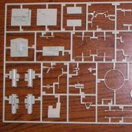
The 1:72 scale model of the S-100 torpedo boat is produced by the German company Revell. I will say a little about the model itself, now there are only such photos of the sprues.


Upon closer inspection, it is clear that all the details are made at a high level, there are no sinks and offsets, there is very little flash. Pleased with a large number of details and the quality of their study. This model immediately, even before the acquisition, was planned for radio control. Its decent length - 500mm, made it possible to make a good radio-controlled boat model. She was also conceived to compete in the F-4A class in ship modeling competitions. Work on the model began even before the creation of the blog, but the idea of it was already there, so some photos of the construction process were taken. The construction of the radio-controlled boat model began with the preparation and gluing of the hull. In principle, the fit of the parts of the model is good, but for convenience, the body, which is almost 500 mm long, I glued in parts.


Then, for the tightness of the case, the entire seam was very well spilled with polystyrene.
Manufacture and installation of stern tubes and helmport pipes
The next stage is preparation for the manufacture of stern tubes and helmport pipes. To do this, I machined bushings on a lathe. For propeller shafts and rudder stocks I will use a bar with a diameter of 2mm. The inner diameter of the bushings of the stern tubes must be maintained strictly according to the diameter of the propeller shafts. This is necessary to ensure tightness. The pipes themselves were made from tubular elbows of antennas of the required diameter. Unfortunately, the photos of the stern tubes were not successful, but I think the point is clear.


The process of making helmport pipes is the same, but here the photos are good and you can see everything on them. We insert bushings into pieces of tubes and solder them well.

Now you need to glue the stern tubes into the hull of the radio-controlled boat. To do this, we first mark on it places for pipes and propeller shaft brackets. We make slots and install stern tubes without glue. To facilitate installation, you can make a fixture, as shown in the photo, for example, from a piece of a floppy disk case.

We set the desired angle of the propeller shafts and glue the fixture to the body. Now you need to make propeller shaft brackets. We grind brass bushings on a lathe, here the inner diameter can be made a little larger. If in the manufacture of stern tubes and helmport pipes, the inner diameter was kept strictly 2 mm, under the existing shafts, then 2.1 mm can be made in the brackets. Since it is practically impossible to set all three points on which the propeller shaft rests on one line. And if there is even a slight misalignment, then the propeller shaft will rotate tightly, which will lead to a loss of motor power, an increase in current in the circuit and excessive battery consumption. On a radio-controlled boat model, small in size, battery consumption is a very important parameter. Since the space and weight of the battery is limited, we will not be able to accommodate a large capacity battery. In each sleeve, with a slot, we make grooves-cuts and solder brass strips there, getting a V bracket, according to the drawing. Can be used as templates for plastic parts of the model. There are several cuts in the part that will be glued into the case, so that later the part will be easier to bend and glue with epoxy resin to the textolite pads.


Now we make cuts in the body of the model for the brackets and put them without gluing. We check the ease of torsion of the shafts, if they rotate very easily, first we bait the stern tubes with a small amount of cyacrine and again check the ease of rotation of the shafts. If everything is in order, you can finally glue the stern tubes. After the cyacrine has hardened, the fixture can be removed. Now you need to glue the propeller shaft brackets. In principle, some colleagues glue them into the case and then shed polystyrene liquid diluted in glue. But after one unsuccessful model, perhaps due to the quality of the hull plastic, where, after this compound dried, the parts moved and pinched the propeller shafts, repeated regluing did not help, I began to make this assembly according to this scheme. Perhaps this increases the time costs, but after gluing, nothing will definitely move from deformation. In small pieces of fiberglass, grooves are cut for the brackets and drilled along the perimeter of a hole with a diameter of approximately 2.5 mm. Then these plates are installed inside the housing so that their slots coincide with the slots in the housing. After that, the holes in the boat hull are marked and drilled so that they coincide with the holes in the plate. Now parts are sharpened from the sprue pieces, like nails. Their small diameter must match the diameter of the holes that are drilled in the plate and in the body. With these parts, gluing them with model glue, we fix the plates on the inside of the boat hull. This operation is necessary in order to be able to glue the propeller shaft brackets to the hull with epoxy resin. During the curing of the epoxy resin, it is possible to control the position of the brackets and, if necessary, correct it. Also, after polymerization of the resin, there will be no deformation of the plastic case and displacement of the brackets. Then you can mark and glue the helmport pipes on the cyacrine. Then, to seal and strengthen the adhesive joints, we lay them with a two-component epoxy putty Epoxy Putty from Tamiya.


Now you can putty the places where the stern tubes and plates for the brackets are installed. To do this, I use BODY SOFT two-component automotive putty.


Automotive putty BODY SOFT hardens quite quickly, after a few hours you can process the body. I do these things at night, so that by the next evening everything will definitely harden.
Motor mount manufacturing
The next stage is the manufacture of the motor mount and the installation of electric motors on it. I bought commutator motors in our Hobby store, apparently they are made in China. It is not possible to establish their type, I can only say that the price tag was written with a supply voltage of 3-12V.

In terms of size, something similar is used in CD-ROMs. By the way, the choice of engines is a very crucial moment in the construction of a radio-controlled boat model. It is necessary to try to choose electric motors in such a way that whenWith the supply voltage you planned and the minimum current consumption, they provided sufficient torque. At this stage, you can also build the layout of the model. In the case, place mass-dimensional models of electric motors, a receiver, steering gears and a power battery. This operation can be carried out in the bathroom. It is necessary to ensure that the model is located in the water as close to the waterline as possible. It is also necessary to avoid rolls and trims. At the same time, do not forget about the accessibility of the elements of equipment and running gear after gluing the deck. At this stage, you need to consider removable nodes to access them. For example, add-ons or some other structural elements. It is also necessary to think in advance about the tightness of the entire structure. I chose a scheme with the entire removable main deck and an oracal false deck. This scheme has been repeatedly tested and proved its viability. Let's go back to the motor mount, I made it from foil fiberglass. Two plates were soldered perpendicularly and between them, for structural strength, a brace was soldered. The motors are attached to the frame with M2 bolts.


First, a base was cut out of foil-coated fiberglass, to which the engines would be attached. Four holes are drilled in it for M2 bolts and two holes for the round part of the engine housing. Then, from foil fiberglass, we make a part that will be attached to the bosses installed on the model body. In it, I drilled two holes for mounting, but still, it's better to think about where to place the third hole. Still, the 3-point mount is more reliable. Then we solder these two parts at an angle of 90 degrees and install a corner for rigidity between them. As practice has shown, it is better to make the part to which the motors are attached from a thicker material, for rigidity.


This is what this assembly looks like with electric motors.


The frame itself is attached to the hull of the radio-controlled boat model on plexiglass bosses with M3 thread.


Installation of propeller shafts and brackets
Now you need to assemble the deadwood assembly - the shaft-brackets. For my Schnellboot S-100 radio-controlled boat model, I used 2 mm shafts from Gaupner. In order not to bend or damage them during the preparatory work, to install and adjust the chassis of the model, spokes from a bicycle were used, the diameter of which is also 2 mm. Since the stern tubes are already glued into the model, it is now necessary to fix the propeller shaft brackets. To do this, we insert the shafts from bicycle spokes into the deadwoods, install the brackets in place and bend their cut parts inside the body.


Then we check the ease of rotation of the shafts in this system. If necessary, we expose and bend the brackets as needed. Ultimately, it is necessary to ensure that the shafts rotate very easily in this entire system. After, with a small amount of epoxy resin, we bait the propeller shaft brackets, gluing them to the textolite pads. During the curing of the resin, we constantly control the ease of rotation of the propeller shafts, if necessary, correct the position of the brackets. This stage is very responsible, since the correct installation and fixation of the deadwood system - shaft-brackets and the ease of rotation of the shafts, in the future, will greatly affect the running characteristics of the model and affect the consumption of batteries. After the final hardening of the epoxy resin, we once again check the ease of rotation of the catch, and if everything is in order, we finally fix the brackets, well spilling the gluing site on the textolite pads with epoxy resin. This photo shows the assembly with the brackets already bent and glued to the epoxy.

The next stage, after fixing the brackets, is the installation of a motor mount with engines. To do this, first, on a lathe, we grind the bosses and cut the threads into them for the screws that will fasten the motor mount. The photo above shows that the bosses are already installed in the case. I will describe in more detail the process of their installation. I made the bosses from plexiglass, and the threads are cut for M3 bolts. To simplify the process of installing a motor mount with engines, we make two simple devices. We grind two bushings on a lathe. Since our propeller shafts and shafts of electric motors have a diameter of 2mm, we make the inner diameter of the bushings 2mm. Their length is about 30mm, and the outer diameter does not really matter. Then, using these bushings, we will connect the motor shafts and propeller shafts into one. We fasten the bosses to the motor mount, and adjusting them, we expose the motor mount in the body so that the propeller shafts rotate with maximum ease.
Connection of electric motors with propeller shafts
After installing propeller shafts and motors on an RC model boat, you need to think about connecting them. There are several different schemes. You can connect these nodes using a flexible connection, such as a spring or using a cardan connection. We will use the second option. To do this, on a lathe, first, from steel, we will machine two bushings with a ball. Let's drill balls for further installation of wire dowels.

Here is a photo of an already installed part on a keyed shaft.
Then we carve, from steel, two cups and make cuts for the dowels. After we drill the cups, on both sides with a 1.6mm drill, and cut the M2 thread for the fixing screws.

Putting all the details together. We machine the limiting bushings on the shafts and solder them so that with the propellers screwed on and the limiting bushings installed, there is a slight play.

Next, at one end of the shaft, we solder the bushings with balls and insert wire keys into the holes so that they move easily. You can see the end result in the photo above. We fix the cups with screws on the shafts of the electric motors. Now we insert the shafts into the deadwoods, install the motor mount in place and assemble everything together.


The next stage is the manufacture of propellers. How to do this is described in the article.
For now, we will use unprocessed propellers.

Now you can apply power to the motors and check how everything works.
Production of rudders for the model
Now you need to make rudders for the Schnellboot S100 radio-controlled boat model. For this model, you need to make 3 pieces. According to the rules, rudders and propellers can be made in several large sizes. If the central steering wheel is quite sufficient area, then the side steering wheels are too small. The pen has the shape of a trapezoid, therefore, first of paper, we will make a pattern. As a basis, you can take the steering wheels from the set and slightly increase the area. After trying on the patterns, we will transfer them to the material from which we will make the details. Here it is better to use stainless and well-soldered metal. For these purposes, I use sheet brass with a thickness of 0.2-0.3 mm. We make a baller from a bicycle spoke, its diameter is 2mm. One end, to the length of the pen, is flattened and turned on an electric grinder. These are the parts prepared for soldering.


We install the baller at the place of the axis of rotation and solder it well with a powerful soldering iron to one of the walls of the pen. Then we bend the pen and solder the trailing edge, then solder the ends.

Here are the raw parts.

Now they need to be processed and give the rudders the desired shape.

By the same principle, we make the central steering wheel. It is somewhat more complex in form, but the essence of the process is similar to that described above. The only difference is that here the leading edge is made of copper tube.


In the end, these are the steering wheels


Hull sealing and buoyancy
The next stage is the installation of watertight bulkheads in the hull. This is necessary in order to provide the radio-controlled boat with buoyancy when water gets inside. For a small model, this is especially critical, since even a small amount of water can lead to its flooding and possible loss. Therefore, we will divide the internal volume into four compartments and install watertight polystyrene bulkheads. Now you can test for buoyancy, for this we will flood the compartments with water.
One compartment flooded.

Two compartments flooded.

Three compartments flooded.

As you can see in the photo, even with the flooding of three compartments, part of the radio-controlled boat remained afloat. From this it follows that in such a situation it is possible to save the model. Thus, it turned out to be divided into four compartments: bow,

the second is the electronics compartment,

third - motor

and stern

with a steering machine and rudder drives. But in order to prevent water from getting inside, it is necessary, in advance, to seal the case well. To ensure the sealing of the internal volume, by gluing the body with an oracal, we glue a polystyrene rim to the sides. To gain access to the electronics compartment, after gluing the bow of the deck, a hatch is made in the bulkhead, rising up. And for the possibility of shooting propeller shafts, holes are made in it, which will then be sealed with oracal.
Steering servo and electronics installations
Now it's time to install the steering machine and electronics on the Schnellboot S100 radio-controlled boat model. To do this, first, let's think about how to mount the servo drive. I made three brackets from a thick sprue and reinforced their fastening with polystyrene corners. The frame itself was made from a plastic plug from a computer. It has the shape of a corner and turned out to be quite a convenient mount.


As a servo, I used a Chinese steering machine HXT-500, weighing 8 grams. I made the rod from a wire with a diameter of 1 mm with latches from an aircraft model cord.

We put everything in place, fasten the frame with self-tapping screws to the sprue racks.


In the second compartment we place the electronics. There will be a receiver and a speed controller.

The deck with the main superstructure has not yet been installed, but in the future they will be glued in and for the possibility of installing and removing electronics, a hatch rising up is made in the bulkhead.


Batteries for the model will be located in the engine compartment. So that the battery does not interfere with the rotation of the propeller shafts, we will make a partition-substrate, also from a computer plug. On the sides, so that the battery does not hang out, we will lay strips of porous packaging material.


The Schnellboot S100 RC boat is now ready for sea trials.
Sea trial video
To be continued…
Marine site Russia no September 21, 2016 Created: September 21, 2016 Updated: November 24, 2016 Viewed: 27985 The purpose of the stern gear is to provide the necessary watertightness of the ship's hull, and the propeller shaft - one or two supports, to perceive static loads from the weight of the shaft and the propeller and dynamic from the operation of the propeller in various immersion conditions.
The stern gears of sea vessels are divided into two groups: with non-metallic and metallic liners.
In the first case, backout, textolites, wood-laminated plastic, rubber-metal and rubber-ebonite segments, thermoplastic materials (caprographite, caprolon), etc. are used as an antifriction bearing material in the first case.
For an oil-lubricated metal bearing, the support bearing shells are filled with babbitt.
During the operation of the ship in the stern tube, constant and variable loads arise under the action of forces and moments transmitted to the propeller shaft from the propeller, which cause stresses in the stern tube bearings and pipes. The motor transmits torque to the propeller, which is not constant.
Periodic changes in torque in the engine-shafting-propeller system cause torsional vibrations. When the frequency of the disturbing forces coincides with the frequency of natural torsional vibrations, resonance conditions arise under which the forces in the parts increase sharply.
Significant efforts are also observed in the near-resonance zones, when there is a partial coincidence of frequencies. In the range of 0.85-1.05 of the calculated shaft speed, the presence of forbidden resonant zones is not allowed.
During operation of the propeller, periodic disturbing forces and moments arise on its blades, which are perceived by the stern tube and transmitted to the ship's hull through its bearings. These efforts arise as a result of a change in one revolution of the screw of its stop and the tangential force of resistance to the rotation of each blade. In this case, conditions may be created under which the frequency of forces arising on the propeller coincides with the frequency of natural bending vibrations of the shafting, which will lead to resonant oscillations of the propeller shaft and high stresses in its main sections.
The total bending moment is the sum of the moment from the mass of the propeller, the hydrodynamic bending moment and the moment from inertial forces during bending vibrations of the shafting.
The hydrodynamic imbalance of the propeller occurs due to the difference in the pitch of each blade or when the propeller is partially submerged. In the manufacture of blades, their pitch differs slightly, but during operation, if individual blades break or deform, the resulting forces can lead to vibration that is dangerous for stern tube bearings. During ballast transitions, due to the difference in thrust, an additional bending moment is created, which leads to a significant hydrodynamic imbalance and, as a result, to increased vibration of the ship's hull.
The load from the mass of the propeller shaft and propeller is perceived by stern tube bearings, which also perceive the built-in static imbalance of the propeller. The maximum part of the load falls on the stern stern bearing and its stern part. During operation, additional loads may occur on the stern gear when propellers hit foreign objects.
The stern tube device is the same for all vessels, regardless of their size and purpose, and consists of a stern tube, inside which there are bearings, and a sealing device that prevents the penetration of outboard water into the vessel. On fig. 1 shows the sterndrive of a single screw vessel with non-metallic bearings, the most widely used in the navy. The bow end of the stern tube 4 with a flange 11 is firmly attached to the afterpeak bulkhead 12, and the aft end is inserted into the stern stem 3, sealed with rubber rings 15 and tightened with a cap nut 16 with a special stopper 2. The sealing rubber is installed between the restrictive collar 14 of the stern tube and the stern stem with on the bow side and the union nut and stern stem on the other side to prevent sea water from penetrating into the space between the stern tube and stern stem.
In the area of the outlet of the stern tube, a gland seal is placed inside the vessel, which includes a packing 9 installed between the shaft and the pipe, and a pressure sleeve 10. The stuffing box has access from the engine room or the propeller shaft tunnel. In the middle part, the stern tube is supported by floors 13, which can be welded to the tube or rest on a movable support, as shown in Fig. 1.
Inside the stern tube, a stern stern tube 5 and a bow 7 are installed with bacout bars or its substitute 6 and 8 built into them according to the "in a barrel" or, less often, "dovetail" schemes. The stern tube bushings are fixed to the pipe with locking screws from turning, ring 1 prevents the longitudinal displacement of the stern bearing bars.
To ensure reliable lubrication and cooling, the bearings are forcibly pumped with outboard water, for which purpose grooves are provided in the set of bearing strips at their joints for the free passage of water. In the backout set, the lower bars have an end arrangement of fibers, the upper ones have a longitudinal arrangement (see Fig. 1, section A-A), since the lower ones perceive large specific loads. Brass thrust bars 18 are installed between the lower and upper slats from the backout, with the help of which they are excluded from turning in the stern tube. To protect the propeller shaft from the corrosive effects of outboard water in the area of the stern tube, it has a bronze lining 17 or is protected by a special coating.
Bearings are mounted in stern tubes - they perceive forces from the propeller and shafting. For the manufacture of stern tubes, steel is used, less often gray cast iron of the grade SCH 18-36. They can be made welded or loose. In the first case, the pipe is connected by welding to the stern stem, the floors of the ship's hull set and the afterpeak bulkhead, in the second case, it is inserted into the ship's hull from the stern or bow and fastened. Insert pipes are made cast, cast-welded or forged-welded. The connection of the stern tube with the stern apple is overwhelmingly cylindrical in length, and in some cases - conical. The wall thickness of the stern tube must be at least (0.1-0.15) dr, where dr is the diameter of the propeller shaft along the lining.
In general, the stern stem, stern tube, hull and reinforced afterpeak bulkhead should be a single well-bonded rigid structure. The insufficient rigidity of this assembly, the absence of a rigid connection of the pipe with the floor of the set, the presence of loose fittings in the connections of the stern tube with the stern shaft do not ensure reliable and trouble-free operation of the stern tube devices, and contribute to increased vibration of the stern of the vessel.
Sealing glands are an important node in the stern tube device. The experience of operating stern gears of large-tonnage vessels shows that the most reliable in operation are such designs that provide not only the rigidity of the assembly, but also a reliable stuffing box seal that prevents outboard water from entering the vessel's hull.
In this case, preference should be given to such stuffing boxes that accommodate both the main and the auxiliary stuffing box, which makes it possible to break it afloat without trimming. The stuffing box can be installed in the bow of the stern tube as shown in fig. 1, or have a remote housing.
Rice. 2. Propeller shaft seals

The remote stuffing box of the stern device (Fig. 2, a) consists of a body 4, which is attached to the flange of the afterpeak bulkhead using studs 7. Inside the stuffing box body there is a packing 3, which is sealed by a pressure sleeve 6 using nuts 5. The auxiliary stuffing box can be sealed with a special brass ring 1, the axial movement of which is ensured by the simultaneous turning of three brass screws 2.
The design of a remote separately fixed stuffing box is irrational, as it overloads the stern tube device and the stuffing box itself with additional loads due to misalignment of the axial stuffing box packing and the shaft.
The stuffing box design shown in fig. 2b. A separate stuffing box 5, together with packing 4, is completely recessed into the stern tube 3, thereby increasing the rigidity of the seal and improving the operation of the stuffing box. Uniform compression of the stuffing box is carried out by rotating one of the six running gears 1, interconnected by a gear wheel 2.
In the considered design, as in many others, auxiliary seals are not provided and, therefore, the possibility of breaking the gland afloat without trimming the vessel is excluded. In this case, the Pnevmostop seal (Fig. 3) of the Kyiv-type icebreaker, which is installed in the aft part of the stuffing box, is of interest.
A water distribution ring 2 is inserted into the body 1 of the bow stern tube until it stops, which is sealed with two rubber rings 5 and locked with screws 9. The water distribution ring has a groove for placing a rubber ring 3 (pneumatic stop) in it with a bronze inner stiffness ring 4.
The pneumostop is fixed with a cover 8 and bolts 7, after which there is a space for stuffing the stuffing box. If it is necessary to stop the access of water to the body, it is necessary to supply air under pressure through channel 6 in the body of the stern tube inside the figured rubber ring of the pneumostop, which will compress the shaft. During normal operation, the gap between the pneumatic stop and the propeller shaft is within 3-3.5 mm, which eliminates their contact.
Reducers are called devices that allow you to lower or increase the number of revolutions of the engine model of the ship, as well as tell the screws the desired direction of rotation. Reducers are installed in the hull of ship models between the engine and the propeller. Most engines for models are high-speed ones. Therefore, they need gearboxes to reduce the number of revolutions and to impart rotation to several screws.
For the manufacture of gearboxes, cylindrical gears are usually selected from various devices, telephone dialers and watch mechanisms, having previously calculated the desired gear ratio.
Gear ratio i shows how many times it is necessary to increase or decrease the number of revolutions at the output of the gearbox. If you need to reduce the number of revolutions in i times, then the number of teeth of the drive gear Z1(the shaft of which is connected to the engine) must be in i times less than that of the driven gear Z2(the shaft of which is connected to the shaft
propeller), i.e.:
If you need to increase the number of revolutions, then do the opposite. Thus, the number of revolutions of the driven gear of the gearbox will always be more or less than the number of revolutions of the drive gear as many times as the number of times less or more will be the teeth of the drive gear.

Rice. 108. Three-stage gearbox.
Sometimes it becomes necessary to make a gearbox with a very large deceleration, for example, for a clew winch for setting sails on a model of a radio-controlled yacht. In this case, a multi-stage gearbox is made, i.e., from two or three pairs of gears. A worm gear is also used for this.
To determine the total gear ratio of such a gearbox, proceed as follows. First, the gear ratio of each pair of gears or worm gear is determined separately, and then they are multiplied together and the total gear ratio is obtained. i. On fig. 108 shows a general view of a three-stage gearbox, consisting of one worm gear and two pairs of cylindrical gears. The total gear ratio of such a gearbox i will be equal to: i1i2i3.
One of the most important quantities in gears is their engagement modulus m. The engagement module is the length in mm per one gear tooth along the diameter of the initial circle, numerically equal to the ratio of the diameter of this circle and the number of teeth. Only gears with the same module provide normal meshing and can be used in a gearbox.
Thus, when selecting ready-made gears, one should first determine their modules. If they are the same, they will work in pairs. To determine the module of a spur gear, you can use the following relationship:
![]()
Where d- outer diameter of the gear;
Z is the number of gear teeth.
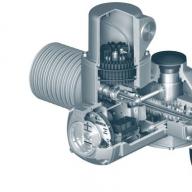
In the manufacture of gearboxes, one should strive to use fine-grained gears, i.e., gears with a larger number of teeth with the same diameter. The use of fine-grained gears reduces friction losses, noise in the gearbox and improves the smoothness of operation. The engagement modulus values are standardized. For the manufacture of gearboxes for ship models, gears with a gearing module of 0.5 are most suitable; 0.6; 0.7; 0.8; 1.0; 1.25 and 1.5 mm. The greater the engine power, the greater the gearing module for the gearbox. So, gears with an engagement module of 1.25 and 1.5 can be recommended for the manufacture of a gearbox only for internal combustion engines (Fig. 109).

Rice. 109. Internal combustion engine with a gearbox.
Gearboxes made with such gears for an electric motor will be very “coarse” and have large losses. For them, it is better to use gears with engagement modules: 0.6; 0.7 and 0.8. The use of gears made of different metals, such as steel and brass, also contributes to reducing the noise of the gearbox and improving the smoothness of its operation. There will be even less losses in the gearbox and the noise of its operation will be reduced if it is placed in a box filled with machine oil, and it will be quite enough if one of the gears of the gearbox plunges into it by only 3-4 mm.

Rice. 110. Diagrams of gearboxes.

Fig.111. Marking the side plate of the gearbox.
The manufacture of the gearbox begins with the manufacture of side plates. They are cut out of sheet brass or steel 1.5-2 mm. The plates must be well straightened on a flat metal plate with a wooden hammer, then put together, clamped with a clamp or in a hand vice and drilled 3-4 mm holes in 4 corners, depending on which bolts they will be connected with. Next, both plates must be connected with two bolts (at opposite corners) and filed along the drawn contour.
Now make an accurate marking of the positions of all gears on one of the side plates of the gearbox. Suppose that a gearbox will be manufactured to reduce the number of revolutions with work on two screws. Then it is necessary to draw two mutually perpendicular lines with a metal scriber - a horizontal line (A1 A2) at a level, depending on the diameter of the gear, and a vertical line (B1 B2) in the middle of the plate (Fig. 111). From the point of intersection of these lines (O), it is necessary to lay aside along the horizontal line the centers of the driven gears - 001 and 002. The distance between these points O1O2 should be equal to the distance between the centers of the propeller shafts of this model.

Rice. 112. Installation of sliding bearings.

Rice. 113. Bushings for ball bearings.
Having scored the centers of all circles, drill holes in both plates at once for plain bearings or ball bearings. Then the plates are separated and sliding bearings are pressed into their holes, machined from bronze on a lathe (Fig. 112), or ball bearings are installed in special bushings or liners (Fig. 113). The best material for bushings is aluminum or brass.
They are attached to the side plates of the gearbox with three screws (Fig. 114). When turning bushings (liners) for ball bearings, it is necessary that the diameter "A" exactly matches the diameter of the outer race of the ball bearing, the cage must fit tightly into place. Dimension "B" should be equal to the height of the ball bearing cage, the wall thickness of the bushing is 2.0-2.5 mm, and the base - 3.0-3.5 mm.

Rice. 114. Mounting gears on the axis.
Axes for gears are machined from steel on a lathe. They should fit tightly into the central holes of the gears. If the gears have cylindrical protrusions, then they can be fastened to the axles with a pin (Fig. 114, A). If there are no protrusions on the gear, the axles are turned with a shoulder (flange) and the gears are attached to it with screws or rivets (Fig. 114, B). When manufacturing axles, it is necessary that the “H” dimension is the same for all axles, and the gears are located symmetrically with respect to them.
On fig. 115 shows the gearbox assembled. The side walls of it can be fastened with studs with shoulders and threaded ends or simple bolts, but with spacer tubes put on the bolts.

Rice. 115. Reducer assembled.
On ship models, internal combustion engines are installed on bases (foundations) made of wood, metal, or a combination of both (Fig. 116).
Electric motors are usually mounted on wooden bases (pillows) or screwed to a reinforced bulkhead of the model hull. Sometimes directly to the gearbox, and the latter to the base, glued into the model body (Fig. 117).

Rice. 116. Foundations for internal combustion engines.
Propeller shafts are made of bar steel with a diameter of 3-6 mm, depending on the propeller diameter and engine power. At one end of the shaft, a propeller with a fairing is installed on the thread, and at the other end, a device for connecting the shaft to the engine or gearbox. Very often, for the manufacture of propeller shafts, bicycle spokes or motorcycle spokes are used.

Rice. 117. Installation of electric motors.
The propeller shaft is inserted into the stern tube, which is a metal tube with an inner diameter of 4-8 mm, at the ends of which brass (bronze, fluoroplastic) bushings (bearings) are pressed in with an inner diameter corresponding to the diameter of the propeller shaft (Fig. 118, A). In order to reduce friction, very often ball bearings are also inserted into the stems, which are pressed into a special bushing, tightly mounted on the stem tube and soldered with tin (Fig. 118, B).

Rice. 118. Stern tubes: A - with brass fluoroplastic bushings; B - with ball bearings; B - with gland packing for submarine models.
To stuff deadwoods with grease, at one end (located in the model case) a short (30-40 mm) piece of tube with a screw is soldered to tighten the grease as it is spent. For submarine models, deadwoods are made completely impenetrable. For this purpose, a bronze (brass) bushing (bearing) is deepened into the stern tube by 8-12 mm and soldered through a specially drilled hole in the stern tube. Part of the free space between the shaft and the deadwood is filled with twine or harsh threads soaked in grease. This filling is crimped with a second sleeve and soldered (Fig. 118, B).

Rice. 119. Connection of engines with propeller shafts.
Deadwoods are installed on the model so that they are, if possible, parallel to the center plane and the design waterline of the model and provide a gap between the propeller and the model hull of at least 0.12-0.28 of the propeller diameter.
If the diameter of the propeller does not allow these conditions to be met, then the deadwoods have to be set at a small angle with respect to the DP and with an inclination to the waterline plane, and on high-speed steerable models this is generally inevitable. It must be remembered that both the opening of the shafts and their inclination by more than 12 ° greatly reduce the efficiency of the propeller. Therefore, on high-speed cord and radio-controlled models, brackets with a cardan are used to ensure the horizontality of the propeller shaft.

Rice. 120. Shaft joints.
The connection of engines with propeller shafts and gearboxes can be varied. The simplest connection of the engine with the propeller shaft is carried out using a spring, a rubber tube, bent hooks on the shafts themselves, brackets and simple clutches (Fig. 119). Such a connection is usually made on small models with low-power electric motors (about 5-10 5 tons) and rubber motors.

Rice. 121. Connection of gearboxes with the engine: A - articulated, roller; B - articulated, flexible roller.
The most common and reliable connection of engines of any power with gearboxes and propeller shafts is a swivel (Fig. 120). This design allows high shaft loads and does not require special alignment of the engine or gearbox with the propeller shaft.
Intermediate shafts between the gearbox and the electric motor can be made from a steel bar with a diameter of 4-6 mm (Fig. 121, A) or from a flexible shaft, for example, from a car speedometer. Such a roller can be made by yourself. To do this, from the OBC wire with a thickness of 1-1.5 mm, a coil is wound close to the coil.
On a lathe, ball tips are machined from steel, inserted from both sides into a spring (Fig. 121, B) and soldered with tin.