39 Measuring instruments for direct measurement of distances.
Measuring lines on the ground is one of the most common types of geodetic measurements. No geodetic work is complete without measuring lines. Lines are measured on horizontal, inclined and vertical planes. They are produced directly - with metal, wooden meters, fly-away, earth-measuring tapes and special wires, as well as indirectly - electronic, filament and other rangefinders. Roulettes are made of steel and tape lengths 1,2,5,10,20,30,50, and 100 m in 10-12 mm awl, 0.15 ... 0.30 mm thick. Strokes are applied to the tape measure - divisions every 1 mm along the entire length or only on the first decimeter in the latter case, the rest of the canvas is marked with centimeter strokes. The numbers are signed at each decimeter division. Steel tape measures are produced either with a canvas wound on crosses, or in a case. For measuring short sections, metal tape measures are made curved in width - grooved. Long tape measures such as RK (on the cross) and PB (on the fork) are used complete with tensioning devices - dynamometers. Tapered tape consists of a dense web with metal, usually copper veins. The fabric of the tape measure is covered with paint and has divisions every 1 cm. tape measures are used when high accuracy of measurements is not being used. Ribbon tape rolls into a plastic case. Survey tape. ЛЗ - steel strip - 20 24 30 and 50 meters, 1 ... 15 mm wide and 0.5 mm thick. One stroke 1 is applied at the ends of the strip, between which the length of the strip is considered. Cutouts are made at the strokes, in which the pins are inserted, fixing the zeniths of the measured segments. The tape ends with handles. On each plane of the tape, divisions are marked at 1, 0.5 and 0.1 mumeters on the tape are marked with half-meter copper plates - rivets. The ZLSh measuring scale tape is distinguished by the presence of scales with millimeter divisions at its ends. The lengths of the segments at the ends of the tape with millimeter divisions are equal to 10 cm. The nominal tape length is the distance between the zero lines of the scales. The set LZ and ZLSh includes sets of 6-11 spire pieces. For transfer, the pins are put on a wire ring. For some types of accurate measurements, special invar wires are used. Invar has a small coefficient of linear expansion. At the ends of the wire, special ruler scales with a smaller division of 1 mm are fixed. The rest of the wire is not marked. Therefore, they measure distances equal to the length between the strokes of 24 m, the distances that are not multiples of 24 m are measured with invar tape measures.
40 Comparison of measuring instruments
Before starting work, measuring instruments are compared with standards - they are compared. Sections of lines in the area or in the laboratory, the lengths of which are known with particular accuracy, are taken as standards. The length l of the measuring tape or tape measure is expressed by the equation, - l = l0 + delta l k + div l t where l0 is the normal length of the tape at normal temperature RF - +20 deg. 2 digit comparison correction, 3 correction due to temperature. To calculate the nominal length of the measuring device for each temperature of the operating mode, you must first determine the value of the correction due to temperature. It is known that the coefficient of linear expansion of steel when the temperature changes by 1 degree = 12.5 x10 to the power of –6. in production conditions, measuring instruments are most often standardized on field comparators. These comparators are flat land areas with predominantly hard surfaces. The ends of the comparator are fixed with signs with special marks, the distance between which is known with great accuracy. Comparison of long tape measures and tapes in the field is carried out on comparators, the length of which, as a rule, is close to 120 m. This is necessary in order to put the measuring device in the comparator several times. The arrangement of measuring instruments is carried out in the forward and reverse directions.
The number of integer and fractional enclosures of the tape or tape is counted and the correction for coping is determined by the formula delta l k = (l0-l e) | n where n is the number of enclosures of the measuring device I e measured length of the comparator.
42 Optical rangefinders. Filament rangefinder.
Rangefinders are geodetic instruments that measure the distance between two points in an indirect way. Rangefinders are divided into indirect and optical and electronic. Optical rangefinders are divided into rangefinders with a constant parallax angle and with a constant basis. The simplest optical rangefinder with a constant angle - a filament rangefinder is available in the telescopes of all geodetic instruments. Three horizontal threads are visible in the field of view of the instrument tube. Two of them are located symmetrically with respect to the middle thread, called rangefinder. The filament rangefinder is used in the kit with a jewel rail, divided into centimeter divisions. The filament rangefinder can measure lines up to 300 m long with an error of 1/300 of the length.
44 Light range finders and radio range finders
electronic measuring instruments are based on the relationship S = vt | 2 known from physics between the measured distance and the propagation velocity of electromagnetic waves along the measured line and back. Due to the peculiarities of radiation, reception and propagation of radio waves, radio range finders are used mainly for measuring relatively long distances and in navigation. Light range finders, using electromagnetic oscillations of the light range, are widely used in the practice of engineering and geodetic measurements. To measure the distance AB, an optical range finder is installed at point A, and a reflector at point B. The luminous flux is sent from the transmitter to the reflector, which reflects it back. The propagation time of light waves is determined in 2 ways - 1 by the direct and 2 by the indirect method. Direct determination of the time interval is carried out in rangefinders, called impulse meters. In them, the measurement of time is made according to the delay of the light pulse received after reflection with respect to the moment of its emission. Indirect time determination is based on measuring the phase difference between two el. Oscillation magician, passive reflection light range finder measure the distance to objects without a reflector, i.e. use the reflective properties of the objects themselves. (DIM-2) range finders with passive reflection and an error of up to 10 mm are currently known.
52) Theodolite survey is a horizontal or contour survey of the terrain, which is performed using a theodolite. Horizontal angles and tilt angles are measured by theodolite. The lines are measured with steel tape and rangefinders of various designs.
Based on the results of theodolite survey, a plan can be drawn up without an image of the relief. To obtain a plan with a relief image, it is necessary to level the surface on which theodolite survey was carried out. It is advisable to use a combination of theodolite survey and surface leveling to obtain a plan of a construction site. The process of theodolite survey consists of the following types of work: laying theodolite passages, linking them to the points of the geodetic network, shooting the situation.
48) The theodolite passages, which are laid in the form of closed polygons and open passages, serve as a planned justification for theodolite survey. When surveying a settlement or a construction site, a closed polygon is usually laid at the border. A diagonal path can be laid inside the landfill to provide a survey of the situation and to control measurements. An open traverse must be elongated, i.e. with angles of rotation, if possible, close to 180 0, and is laid, as a rule, between points of triangulation or polygonometry.
The laying of theodolite passages begins with securing the tops of the turning angles with pegs or wooden pillars on the ground. The points of the turning angles of the theodolite traverse are chosen so that the sides between adjacent points are conveniently measured, and their lengths are no more than 350 m and no less than 20 m. The lines are measured twice, in the forward and backward directions. The angles of rotation in theodolite moves are usually measured by the right-handed march lying. Measurements are performed at two positions of the vertical circle and the average of the two measurements is taken as the final result if the difference does not exceed double the accuracy of the instrument. The slopes of the lines are measured using the vertical circle of the theodolite. The results of angular and linear measurements are recorded in a log of the established form.
49) In a theodolite survey, a geodetic log of measurements of angles, lines and outlines is obtained. These documents serve as the basis for building a plan. Therefore, the processing of the results of field measurements begins with checking the correctness of all records and calculations made in the log, as well as calculating corrections for the inclination of the sides of the theodolite line. Further processing of measurements in a theodolite survey consists of the following actions: processing of angular measurements and calculation of directional angles and points of sides, calculated increments and coordinates of theodolite traverse vertices, construction of a plan of theodolite survey area.
Angular misclosure of a closed traverse. f b = åb n -180 0 (n-2)
The admissible limiting discrepancy of the sum of angles f b = 1`√n, is distributed with the opposite sign equally on all angles, rounded to 0.1`
Calculation of directional angles and points of the sides of the closed course. The initial directional angle a 1 is obtained by binding the side to the points of the geodetic network or determining its true or magnetic azimuth. From the known directional angle a 1 and corrected angles b, the directional angles of all sides of the closed course are calculated by the formulas: a n = a n-1 +180 0 -b n; a 1 = a n +180 0 -b 1 (measurement control)
Angular misclosure of an open traverse f b = åb n -åb т
57) A geodetic network is a system of fixed points on the earth's surface, the position of which is determined in a common system of geodetic coordinates. The geodetic network is of 2 types: planned and high-altitude. In Russia, geodetic networks, both planned and high-altitude, are subdivided into a state geodetic network, a geodetic network of condensation and a survey geodetic network. The state geodetic network is the starting point for the construction of all other geodetic networks. The dense network serves to further increase the number of points of the geodetic network. The survey network is a geodetic justification for the production of topographic surveys, as well as for performing various kinds of engineering and geodetic works.
Planned geodetic networks are created by triangulation, polygonometry and trilateration methods.
When building a geodetic network by the method of triangulation, a number of points are fixed on the ground, which together form a system of triangles. In triangles, all angles and some sides are measured, which are called basic.
The polygonometric method consists in building broken lines on the ground, called polygonometric moves. These moves are usually laid between the points of triangulation. Polygon strokes measure all angles of rotation and lengths of all sides.
When building a network using the trilateration method, a network of triangles is also built on the ground, in which all sides are measured with the help of light and radio range finders.
The high-rise geodetic network is constructed by the method of geometric or trigonometric leveling.
51) Survey of the terrain is carried out, depending on the specific conditions of the terrain, by one of the following methods: rectangular coordinates, polar, right angular serifs, linear serifs, traversal, sections.
When surveying by the method of rectangular coordinates, the position of each situational point of the terrain is set according to the values of the abscissa X (the distance from the nearest point of the survey justification on the side of the theodolite traverse or the distance from the beginning of the track) and the ordinate Y (the distance from the corresponding side of the theodolite traverse or from the track). The determination of the ordinates Y is usually done using a mirror ecker and a tape measure.
The method of rectangular coordinates is most often used when surveying the road strip of linear structures during the stakeout of stationing. The width of the survey of the roadside strip at a scale of 1: 2000 is taken at 100 m on both sides of the track, while within the expected right-of-way the survey is carried out instrumental, and then visually.
Theodolite survey by the method of polar coordinates is used mainly in open areas, while the position of each situational point is determined by the horizontal angle b, measured from the corresponding side of the theodolite traverse, and the distance S, measured from the corresponding point of the survey justification. The survey of characteristic points of the terrain is most often carried out by optical theodolites with measuring distances with a filament rangefinder.
Polar surveying is particularly effective when using electronic total stations.
The method of direct angular serifs is used mainly in open areas, where it is not possible to directly measure the distances to points of interest in the terrain. The position of each surveyed point relative to the corresponding side of the theodolite traverse is determined by measuring two horizontal angles b1 and b2 adjacent to the baseline. The basis is usually one of the sides of the shooting rationale or part of it. Angular surveying is usually carried out with optical theodolites and is especially often used in hydrometric work on rivers: measuring surface flow velocities with floats, trajectories of ice floes and river vessels, when performing underwater surveys of the bottom of river beds and reservoirs, etc.
The method of linear serifs is used if the terrain conditions make it easy and quick to make linear measurements to the characteristic situational points of the terrain. Measurements are made with tapes or tape measures from bases located on the sides of the shooting base. The position of each surveyed point of the terrain is determined by measuring two horizontal distances s1 and s2 from different ends of the base.
The bypass method implements the location of the theodolite traverse along the contour of the object being shot with the binding of this traverse to the survey justification. The angles b1, b ..., bn are taken at one position of the theodolite circle, and the measurements of the lengths of the sides are carried out with a survey tape or tape measure, a thread range finder or an optical range finder of an electronic total station.
The bypass method is used, as a rule, in a closed area to indicate inaccessible objects of a large area.
The essence of the method of crossings is that directly between two known points located on the sides of the survey justification, using one of the measuring devices, the position of the characteristic situational points of the terrain is determined.
The method of crossings is used mainly in the search for airfields, for establishing the situational features of the terrain in the course of topographic surveys by the method of geometric leveling in squares. When conducting surveys of other engineering objects, the alignment method is used extremely rarely.
50) Theodolite survey is a situational survey in which the horizontal angles are measured by the theodolite, and the horizontal
projection of distances by various measuring instruments. The elevations between the points of the terrain are not determined at the same time, therefore theodolite survey is a special case of tacheometric survey.
Tacheometric survey is the most common type of ground topographic surveys used in engineering surveys of construction sites. The high productivity of tacheometric surveys is ensured by the fact that all measurements necessary to determine the spatial coordinates of the characteristic points of the terrain are carried out in an integrated manner using one geodetic device - a tacheometer theodolite.
To draw up topographic plans for areas with a weakly expressed relief, an increased accuracy of topographic survey is required. In such cases, the geometric leveling method can be applied, which is built in the following ways:
The way of cross-sections to the main course.
Parallel line method
Polygon method
Squares way
Phototheodolite surveying allows you to determine the coordinates of points of the terrain and draw up topographic plans, as well as prepare digital terrain models from photographs obtained when photographing the earth's surface.
Aerial photography is a complex of works performed to obtain topographic plans and digital terrain models using materials from photographing the terrain from aircraft or from space.
In the manner determined by the Government of the Russian Federation; - organization and support of military and special rail transport; - management of mobilization training and civil defense in railway transport; - implementation of state control (supervision) over the activities of individuals and legal entities in railway transport, including in terms of safety ...
Particularly in relation to services that may affect the health of citizens or damage the environment). Technical regulations will be of two types: general (for example, on environmental safety issues) and special (taking into account specific types of activities). Standardization will be voluntary. Licensing of certain types of activities in the field of environmental protection. IN...
Assistance provided to commercial organizations that are legal entities under the laws of the Russian Federation, in the form of subventions, subsidies, budget loans, incl. in the form of resources other than cash. Thus, the relationship between the enterprise and the budget only goes through taxation. In this case, the company has the right to use all provided by the legislator
Cultural and Ethnographic Museum-Reserve "Kizhi"; Gosfilmofond RF; State Memorial and Natural Reserve “Museum-Estate of L.N. Tolstoy "Yasnaya Polyana"; Moscow Factory of Decorative Painting; Russian State Archive of Ancient Acts; - objects necessary for the functioning of federal bodies of state power and the solution of all-Russian problems. These include ...
We will send the material to you by e-mail
IN construction and household repair work requires absolute measurement accuracy. Correct measurements will prevent unpleasant situations such as mismatching seams, gaps between the wall and the finish. A separate profile tool is used for each type of work. What tools are used to measure distances, we will tell in this article.
- metal tape measure;
- laser tape measure;
- micrometer;
- level;
- calipers.

In construction stores you can find any construction tool you are interested in. Also, many companies offer a rental service for such devices, which reduces construction and renovation costs. In addition, this procedure excludes the purchase of low-quality construction tools. Also, you can use several models and choose the best one to purchase for personal use.
Metal tape measure
Available in nominal spacings up to 20 m with a catch mechanism at the free end. They are used for simple measurements indoors and outdoors.
Advantages:
- The ability to take readings in any weather.
- Environmental Safety.
- Lack of batteries.
- Long service life.
- Minimum error.

Flaws:
- Fixed maximum length.
- Impossibility to use in hard-to-reach places.
- With frequent contact with water, corrosion may develop.
- Large dimensions.
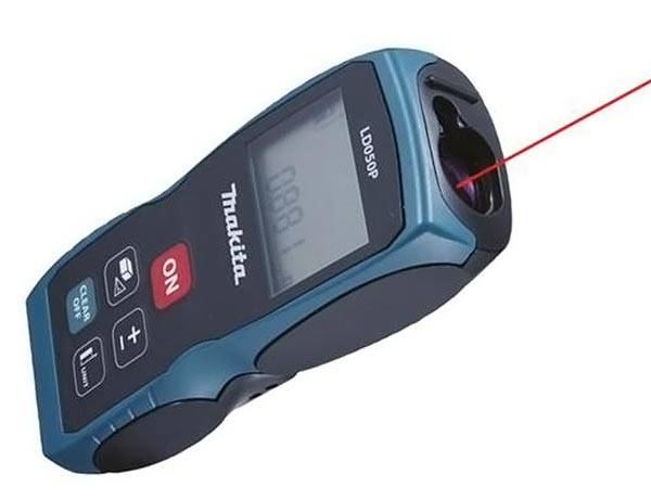
Laser tape measure
What tools should be used to measure long distances in hard-to-reach places? Conventional equipment has been replaced by laser tape measures that can measure long distances. This is a highly technical device that quickly and accurately takes readings of any level of complexity.
Flaws:
- Price. Almost all models have a high price tag.
- The need to use a tripod for taking readings at long distances.
- Large error when measuring short lengths.
- In cold weather, the battery may drain quickly.

To improve the accuracy of the readings, a target is placed on the end point. Save measurement results in memory to select the best repair option.
Cheap Chinese counterparts give a large error over the entire measurement range. It is not recommended to use such roulettes to remove control and critical digits.
Related article:
Short Distance Measuring Instruments
What tools are used to measure small distances, such as the diameter of wires, bolts, fittings, etc.? There is only one answer - high-precision. These include a caliper, bore gauge and micrometer. The desired object is placed between the strips or clamps of the measuring device that correspond to the data on the scale. Built-in bayonets or rods are used to measure the depth of hollow objects. The accuracy of the readings is calculated to a tenth of a millimeter.


Levels
What tools are used to measure distances on the ground and on flat surfaces? These are levels. They are widely used for finishing works - laying tiles and solid wall and floor materials, for taking data about buildings and ground levels. With the help of the device, you can make accurate markings, formulate the correct direction of the walls, etc. Standard devices are equipped with an eyepiece and a scale, new ones use laser beams. Levels can only be used in conjunction with tripods to improve the accuracy of readings and avoid shaking the device during operation.

- Buy measuring instruments from trusted hardware stores. On the market, you can often find fakes, which, after several uses, will become out of order.
- If you do not plan to use the device in the future, you can save money and rent the equipment for the required period.
- Check instruments before responsible measurements. Even the most expensive equipment can fail. A routine check can do a good job for you.
- Do not leave battery powered devices on. After deep discharge, the battery may lose some of its capacity.
- It is not recommended to use battery-powered devices outside in severe frosts, low temperatures adversely affect the operation of any devices.
Conclusion
Choose only high quality distance measuring devices. The success of construction and installation works... Use measuring devices at all stages of construction to minimize measurement errors.
The invention relates to geodetic instrumentation and is intended for measuring distances of various lengths in the construction of geodetic networks for the construction of unique structures, for example, charged particle accelerators, reactor rooms, as well as the installation of equipment for nuclear power, rocketry, etc. The device contains a measuring tape 1 with holes 2, housing 3 with a base 4, a frame 5 with a support prism 6, a base support 7 with a whole 8, a groove 9 for fixing the base of the body, a pin 10, a retainer 11 with a fixing screw 12; a base element 13 with a carriage 14, a balance bar 15 with a load 16 and 17 as a whole, level 18, a tensioning micrometric screw 19 and an indicator 20. The use of tape 1 with holes 2 as a flexible working measure allows one tape to measure lines of any length, since the tape with holes is a set a large number end measures. The proposed device increases the accuracy and productivity of distance measurement, ensures the use of tapes from different materials requiring different tension. 1 wp f-ly, 2 dwg.
The invention relates to geodetic instrumentation and is intended for high-precision measurement of distances of various lengths in the construction of geodetic networks for the construction of unique structures, for example, charged particle accelerators, reactor rooms, as well as the installation of equipment for nuclear power, rocketry, long-distance radio communication, etc. a tape installed in it with the ability to move with a screen with opaque strokes fixed on it, a second screen rigidly fixed to the body, a light source, a photodetector and computing unit installed one by one or different sides from the screens. Structurally, the tape is made in such a way that measurements are made between two hooks, one of which is located at the end of the tape, the other on the body. This makes it easier to measure linear dimensions, for example, of structures, but it complicates high-precision measurements between geodetic standard marks and reduces the accuracy of measuring the tape measure on the comparator, which excludes its use for high-precision measurements in geodetic networks. Known is a device for measuring distances containing a flexible working measure and a counting and tensioning device associated with it through a connecting device. In the known device for measuring distances, the control of tension and counting on a flexible working standard is automated, which ensures high accuracy and productivity of measuring the length of the line corresponding to the size of this flexible working standard. Since with the length of the flexible working standard a, it is possible to measure lines in the range d d, where d is the displacement of the carriage, the device must have a set of flexible working measures that can measure various distances. This makes it difficult to use a device for measuring lines of arbitrary length; moreover, the replacement of one flexible measure with another increases the labor intensity of the work and reduces the labor productivity. The closest in technical essence to the invention is a device for measuring distances containing a base support, a base element, a carriage mounted on a base element with the ability to move in a direction perpendicular to its axis, a balance bar with a weight mounted on a carriage with the ability to rotate in a plane passing through the axes of the base support and the base element, a measuring wire fixed at one end on the base support and the other on the balance bar, a level for determining the relative position of the balance bar and the measuring wire, and a reference device serving simultaneously as a tensioner. The known device is intended for high-precision measurements, but has poor performance labor, since one wire can measure the distance in the range d d, where d is the length of the wire, and d is the amount of movement of the carriage. To measure lines of different lengths, it is necessary to have the required number of measuring wires, which increases the laboriousness of measurements and their certification. In addition, in the known device, the movement of the carriage and the reading of the amount of movement is carried out by the same micrometric screw, which affects the metrological characteristics of the device and reduces the accuracy due to wear of the screw. The object of the invention is to develop a device for measuring distances, providing high-precision measurement of lines of any length. This is achieved by the fact that in a device for measuring distances containing a flexible working standard, fixed at one end on a base support, and the other on a base element with a carriage, a single-arm balancer with a weight and a level for determining the relative position of the balancer and a flexible working standard, the reference and tension devices, according to the invention, the flexible working measure is made in the form of a tape with holes along its axis with intervals between them not exceeding the stroke length of the carriage, the base support in its upper end is equipped with a pin and a fixator for the position of the flexible working measure and the hole, and the balance arm is made with the possibility changing its length, while the tensioning device is made in the form of a micrometer screw fixed to the end of the carriage and is not functionally connected with the reading device. A flexible working measure in the form of a tape with holes along its axis with intervals between them not exceeding the travel of the carriage is a set of a large number of gauge measures. The possibility of measuring with a tape with holes is provided by the design of the base element, equipped at the upper end with a pin for fixing the tape with a hole on it corresponding to the measured length of the line, and a clamp that contacts the edge of the hole with the pin, which increases the measurement accuracy. The implementation of the balancer with the possibility of changing the length of the arm allows the use of the base element for measuring with tapes of different lengths (10 or 24, or 48 m) by selecting the required tension of the working measure, which expands the possibilities of using the device for different types geodetic works. In the proposed device, a micrometer screw is used to improve the metrological characteristics of the tape tension, and a dial indicator is used as a reading device. The functions of the reading and tensioning devices are separated. FIG. 1 shows a device for measuring distances, general view; in fig. 2 flexible working measure, plan. The device for measuring distances contains a measuring tape 1 with holes 2, a body 3, a base 4 of the body and a frame 5 with a support prism 6; base support 7 with the whole 8, groove 9 for fixing the base of the case, pin 10, retainer 11 with a fixing screw 12; a base element 13 with a carriage 14, a balance bar 15 with a load 16 and 17 as a whole, level 18, a tensioning micrometer screw 19 and an indicator 20. A flexible working measure in the form of a measuring tape 1 with holes 2 is located in a housing 3 with a base 4. A measuring tape is made, for example, from invar tape 8 mm wide, 0.2 mm thick. Holes 2 on the tape are punched using a special template and a punch. For fastening the body 3 of the tape 1 in the groove 9 on the pillar 8 of the base support 7, the base 4 is made in the form of a fork. One end of the tape is fixed on the base support 7 by the nearest hole 2 in the pin 10 and by the fixator 11 of the tape and the hole position. The other end of the tape is fixed on the base element 13 by means of a measuring frame 5 with a support prism 6 to facilitate contact with the whole 17 mounted on the balance bar 15 with a weight 16. The spring-loaded carriage 14 is placed in guides located on the base element 13 for movement. The intervals between the holes 2 on the tape 1 should not exceed the step of movement of the carriage 14 to ensure quick fixing of the hole 2 corresponding to the "rough" value of the length of the measured line. If the holes are punched through 50 mm, then the "rough" value of the line length is equal to nl o, where l o = 50 mm, n is the number of holes. The carriage 14 has, for example, a hinge connection with the balancer 15, which serves to accommodate the load 16 with the whole 17 to secure the end of the tape 1. The implementation of the balancer with the possibility of changing the length of the arm allows the use of the same base element for measurements with tapes of different lengths (for example , 10 or 24, or 48 m) and sections, as well as made of different materials (steel, invar, composite materials) by selecting the required tension of the working measure by moving the load on it. Level 18 provides the same position of the balance bar 15 and tape 1, corresponding to the required tension for a given measured body both at the time of device certification and at the time of measurements. The tensioning device 19, which moves the carriage 14, and therefore the balance bar 15 to the position corresponding to the required tension of the tape 1, is made in the form of a micrometer screw, readout for measuring the amount of movement of the carriage 14, for example, in the form of a dial indicator 20. Tensioning and reading devices are located at opposite ends of the carriage 14 to unload the indicator from the stress of the spring-loaded carriage 14 in order to increase the metrological characteristics of the reading device. Before starting measurements, working tape 1 undergoes metrological certification. First, on a high-precision meter of the UIM-23 type, the distances between the holes are measured, and then the lengths between the holes are compared with the standard through, for example, 1-5 m. Further, from the processing of the comparison results, a certification is made for each hole. In addition, during the comparison, the count a 0 is determined by the indicator 20, corresponding to a predetermined tension achieved at a certain position of the balance bar 15 of the measuring tape 1 at the position of the level bubble 18 at zero point. For example, for a 24-meter belt, the tension should be 10 kg. By solving and analyzing the equilibrium equations of the one-shoulder balance bar 15, the mass of the load 16, which can move along the axis of the balance bar, is found and the place of its fastening (the shoulder of the force application) is determined. Next, adjust the level 18 so that, with a tension of 10 kg, its bubble is at zero point. With this adjustment, it is allowed to use spacers if the range of the level 18 correction screws is not enough. Level 18 is used to control the relative position of the balance bar 15 and the tape 1 at a given tension during comparison and field measurements. After alignment of the locating element 13 and comparison, the device is ready for operation. In the bushings of geodetic signs, the distances between which must be measured, insert the base support 7, and the base element 13 with a spring-loaded carriage 14 installed on it with a balance bar 15, a weight 16, the whole 17 and level 18. The body 3 of the tape 1 with the base 4 is placed in the groove 9 , on the pillar 8. Pull the tape 1 out of the body 3 and fix its end with the frame 5 and the support prism 6 on the pillar 17. Unscrew the fixing screw 12 of the retainer 11 and take the latter to the side, pulling the tape, insert the pin 10 into the nearest hole 2. this, the tape 1 is placed in the groove on the upper end of the rear sight 8, the latch 11 is returned to the working position and the tape 1 is pressed with it using the fixing screw 12. Further, the balance bar 15 is oriented in the direction of the measured line so that the axis of the balance bar coincides with the plane passing through the axes of the base support 7 and the supporting element 13. To measure the length of the line on the indicator 20, the correctness of the setting of the reference a 0 determined during comparison is checked. In the event that the countdown is knocked down, acting with a tension micrometer screw 19 and changing the position of the indicator 20 in the holder, they achieve its installation in accordance with the metrological data. By rotating the screw 19, the carriage 14 with the balance bar 15 is moved until the bubble of the level 18 is set at zero point. The count of the position of the carriage 14, corresponding to the length of the tape from the fixed hole 2 to the edge of the support prism 6, is determined by the indicator 20. The length of the line L is equal to L = nl 0 + (a-a 0), where n is the number of the hole; l o the distance between the holes on the tape; a reading on the indicator when measuring; a 0 is the reading on the indicator when comparing.
Claim
1. DEVICE FOR MEASURING THE DISTANCE, containing a base support, a base element with a carriage, a flexible working block fixed at one end on the base support, and the other on the base element, a reference mechanism interacting with the carriage, a tensioning mechanism for the working measure and a balance bar with a weight, which is different the fact that the flexible working measure is made in the form of a tape with holes along its axis, the intervals between the holes of which do not exceed the step of movement of the carriage, which is pivotally connected to the balancer, the load is placed on the balancer with the ability to move along it and fix, the device is equipped with a base support a pin designed for alternate placement in the holes of the tape, and a fixer for the position of the tape. 2. The device according to claim 1, characterized in that the tensioning mechanism is made in the form of a micrometric screw interacting with the end face of the carriage and located diametrically relative to the reference mechanism.
When people pass by surveyors working on the streets, construction sites, in garden plots, many ask the question, what kind of "tripod" is this, where to look into the device, and what will I see there? What is the name of this device, and why is it here? Often it is idle curiosity. Sometimes they just try to delve into and understand how it works and what it measures. Some just work in related industries and want to broaden their horizons.
There are very complex systems and ultra-precise devices that are rarely used, and in the ordinary life of an engineer you will not meet with them. Let's try to briefly tell you about the devices that are mainly used by surveyors in applied geodesy. About those tripods and "sticks" with which surveyors go.
»
»
»
»
»
»
»
| A small historical sketch |
|
The famous Russian professor-surveyor who lived and worked at the turn of the 19th and 20th centuries, Lieutenant General Vasily Vasilyevich Vitkovsky called his specialty one of the most useful areas of knowledge. In his opinion, humanity needs to study the shape and surface of the Earth just as much as each of us needs to know our own home in detail. It is not surprising that geodesy is developing all the time and has long been aimed not only at our separate planet, but also at the entire solar system and even the galaxy in the future. Along with the development of civilization, this science became very complicated, divided into several disciplines - and, naturally, began to set itself and solve more and more complex problems. Moreover, both theoretical, due to the growth in the number and scope of research, and practical, due to the increase in the number of unique engineering structures and structures. This could not but lead, on the one hand, to an increase in the requirements for the accuracy of measurements, and on the other, to the complication of equipment. This has become especially noticeable in the last 10-20 years in connection with the rapid development of electronics and the beginning of the widespread use of lasers. More information about geodesy, as a science, can be found in the dedicated to this cognitive topic. |
What geodetic instruments measure:
Distance measurement
The simplest surveying task is measuring the length of a line. Tapes and tape measures, long meters and geometric-type rangefinders are devices with which short lines are measured with relatively low accuracy. But if we are talking about high-precision or basic measurements, as well as significant distances, you will need a rangefinder - light, electromagnetic, radio wave or laser. Such devices are especially common in space and marine geodesy.
Excess measurement
Levels and profilers are used to measure heights and their differences. Levels are used in conjunction with special leveling rods. There are optical, digital and laser levels. Moreover, the latter should not be confused with just laser levels, which differ not only structurally, but also in ensuring accuracy.
Angle measurement
Measurement of angles was provided for a very long time using fairly simple tools.
- transports, ekers and eclimeters. A more complex instrument is the compass - a subspecies of the compass, which can measure the magnetic azimuth, that is, the angle by which the line deviates from the northward direction of the magnetic meridian. The main modern device for measuring angles is the theodolite, a rather complex optical device that allows achieving very high measurement accuracy.Locating
In ancient times, determining the location worried sailors most of all - there is no one to ask, and there are practically no landmarks. Many specific devices were created to navigate and determine the latitude of their location - an astrolabe, a sextant, a quadrant and other rarities. Nowadays you will not surprise anyone with "navigators" on various electronic devices. This became possible with the advent of special navigation satellites, which make it possible to directly determine the location of an object on the ground.
It's not a secret for a long time - progress does not stand still. The time when all these values were measured separately, and even with "grandfather's" devices, is irrevocably a thing of the past. Within the framework of this article, we will not consider compasses, kipregels and steel tape measures - only the actual and most common geodetic equipment.

Each self-respecting geodetic team of 2-4 people, in order to cope with almost any engineering and geodetic survey, must have the following devices:
.
It is clear that measuring angles, lengths and heights with different devices is not very convenient and takes a long time, besides. Therefore, for those cases when it is necessary to carry out several types of measurements, there are combined instruments, such as a total station. This is the most modern electro-optical device that allows you to measure any lengths, height differences and horizontal angles.
In most cases, this device is sufficient to record all the necessary measurements on the object, provided that the accuracy of the device corresponds to the type of work. It is these devices, for the most part, you can see on construction sites, on the sites of neighbors and along the roads of our country. at this stage of technology development, they are the most popular and versatile instruments for conducting geodetic measurements.
In many cases, there is no need for more bulky and much more expensive and complex total stations. In the construction of buildings, roads and other structures, after the planned determination of the location of the object, it is only necessary to control the height, level and verticality of surfaces. These functions are easily handled by the level. Its main task is to measure the height difference between objects. There are electronic, optical, laser, auto-alignment levels and others. In many cases, it is more convenient and more expedient to use levels - for example, when observing the precipitation of buildings and structures, high-precision levels with auto-setting are used, rather than tacheometers, again due to the high cost of the latter... Summing up a certain line of use, we can say that most often they are used directly in the construction process because of their ease of use and relative cheapness.
-GPS equipment

GPS modules or receivers accompany us in Everyday life in our phones, navigators, tablets, etc. They are designed to help us navigate the terrain and not get lost in the urban jungle. However, they have little to do with GPS surveying equipment.
Surveyors need these devices not to orient themselves on the ground, but to accurately determine the location of the "dish" (usually the manufacturers of GPS receivers adhere to this form). The error is usually 0.5-2 centimeters relative to the nearest point of the State Geodetic Network (GGS). While ordinary navigators give a location error of about 10-20 meters, which is unacceptable in the work of a surveyor. But there are many factors that very often negatively affect the magnitude of the geodetic error. Therefore, it is not enough just to purchase an expensive "plate" and begin to determine the location of neighboring fences, for example, as with an ordinary navigator. Without proper calibration and post-processing of measurements, nothing will come of it.
In general, if you see a surveyor with a "saucer" on a pole, you should know that he determines the exact location of the point over which the receiver is standing.
 A very simple surveyor tool. Many have come across tripods when shooting photos or films using professional equipment. Surveyors also use special equipment that cannot do without tripods. Geodetic surveys differ from the rest mainly in their simplicity of construction, unpretentiousness in use and "indestructibility". After all, you have to work in less than ideal conditions. The main task of a geodesic tripod is to fix the device, which is installed on it, immovably. First, a tribrach is placed on the tripod - a special device for centering over a certain point, if necessary, and leveling the device. Then the instrument-tacheometer, level, etc. is already put. Distinguish between wooden, metal and composite tripods. IN recent times the most "advanced" are fiberglass tripods. They are very light, durable ... but so far they are unreasonably expensive.
-Packet
Also a fairly simple geodetic instrument. It looks like a round stick about 1.8m high. However, many of the poles are expandable and can be up to 6 meters high. At the top there can be both a reflector and a GPS receiver. The reflector can be different shapes and designs. Its main task is to reflect the signal sent by the rangefinder. Its peculiarity is that the beam / signal coming from the measuring device is reflected exactly back.
Ultimately, where there is a reflector or receiver on a geodetic pole, the location of the measured point is determined.
It appeared relatively recently in geodetic brigades, as it used to be quite expensive and difficult to use. To this day, it is not the only device for directly measuring distances on an object. Convenient to use over short distances and indoors. In outdoor conditions, it is not often used, since it is necessary to have a surface on which the laser beam can be directed. Also, a minus of many models without an optical sight is poor visibility of the laser point on brightly lit surfaces.
In view of this, nowadays it is still quite often necessary to use steel tape measures up to 50 m long. Longer lengths are not produced, therefore, distances over 50 meters are sources of errors due to several measurement steps. Measurements need to be carried out together, and the slack of the tape causes some measurement error.
As a result, laser tape measures are used universally by cadastral engineers and surveyors in cases where it is appropriate and possible. In other cases, the good old steel tape helps out.
A device accompanying engineering and geodetic surveys for drawing underground utilities on the plan. Often a generator is included in the kit, which is installed on the communication in its visible part. It generates vibrations that are recorded by the receiver. After detecting the turning points of communication, they are applied to the geo-base or. The cable finder can also measure the depth of the communication with an accuracy of 0.05m.
We have briefly told you about geodetic instruments and instruments required in applied geodesy. We hope that we have helped to understand the intricacies of tripods and "sticks" with which people who call themselves surveyors work.
Useful articles:
At the initial stage of the development of geodesy, the main tasks were measuring straight lines, construction of a right angle, measurement of areas and orientation of structures during construction. Appropriate devices and tools were created to solve them. When erecting monumental structures, it was necessary to know the lines plumb line and the horizon... Descriptions of some devices and measurement methods are in the writings of Vitruvius and Heron's "Diopter". In the "Bible" in the "Book of the Prophet Ezekiel" tells about "a measuring reed six cubits long" (called the rod of Ezekiel).
In Egypt, as measuring devices and devices for direct measurement of distances and geometric constructions on the ground, they used measuring cords and poles... In ancient Greece and Rome, in addition to them, were used measuring chains, square, ruler, compasses, spirit level with a plumb line, thunder, diopter, odometer, water levels, etc.... According to the ancient historian Pliny the Elder plumb line invented by the famous mythological mechanic, architect and sculptor Daedalus, compass created by Perdix, the son of Daedalus' sister, and spirit level with a plumb line, ruler and square- Fyodor of Samossky. They were used until the collapse of the Roman Empire, and the simplest - until the 17th century. in Europe and the Arab Caliphate. Some tools are still used today (plumb line, square, level). The ancient Greek astronomer Hipparchus invented a goniometer device named later Armillary sphere(rice.). It has been used extensively for centuries in astronomical observations.
Measuring ropes from the description of Heron of Alexandria were made as follows: the rope was soaked, kept stretched between two stakes and dried several times, then rubbed with wax and resin. According to Geron, such a rope did not differ in length from the chain by more than 1: 2000 (1cm by 20m). The rope was marked out at equal lengths. On it, parts of 3,4,5 units were also marked with nodes to build a right angle on the ground.
The following triplets of numbers were also known in India: 5,12,13; 7.24.25; 8.15.17; 12.35.37. ("The Rules of the Cord", Fischer, 1981, Paris).
In China in the 11-10th centuries. BC. measurements of "the whole Earth" were made using dimensional chains.
In many countries, land surveyors and land surveyors were called "pulling ropes". Egyptian land surveyors were called harpedonapts, which means stretching, securing the rope, Roman - agrimenors, in Russia - ropemen... In many ancient sources, a rope of a special length is referred to as a unit of length. The measured rope has left its mark on some fundamental geometric terms, such as the concept the line means a stretched thread. .
The sizes of objects were determined by measuring only straight lines. Dimensions (edit) individual elements figures on the ground were determined by measuring or postponing a given distance along the direction taken out on the ground. In geodetic work up to the 16th century. angular measurements were not performed.
Ancient people were able to measure distances to distant objects indirect means based on proportional division, by means of laths, a pole or a wand. Not only individual rails were used, but also sets of fastened rails, which constituted the simplest measuring instrument. - square, horizontal or vertical. Thales used to determine the heights of objects shadow length measurement method... Using this method, he (in the 6th century BC) measured the height of the pyramid, noting that the length of its shadow is in the same relation to the length of the shadow of the vertical pole as their height (Plutarch "The Feast of the Seven Wise Men"). He determined the height of the pyramid by observing its shadow when a person's shadow is the same length as himself.