If you are working on a drawing, then you definitely wondered: how to make dimensions in AutoCAD? After all, it is an essential element of any project.
In the previous article, we have already considered how to set the size in AutoCAD, in addition, the main points of their application were studied. Now is the time to talk about how to adjust the dimensions so that their appearance meets the necessary requirements for the drawing. Now we are talking not only about the size of the text, but also about its orientation and location, the accuracy of numerical values (i.e., the number of decimal places), the appearance of the arrows (serifs, dots, etc.), as well as setting up remote / dimension lines (color, type, weight, etc.).
How to adjust dimensions in AutoCAD?
The dimension style is responsible for the external display of dimensions in the drawing. It is enough to configure it once, save the drawing as a template and then apply it in your work without wasting time editing dimensions.
So, in AutoCAD, you can change the size, or rather, customize its appearance, in the Dimension Styles Manager. There are several ways to bring up this dialog box:
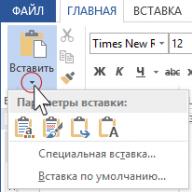
On the "Home" tab - on the "Annotations" panel, expand the drop-down list and click on the small icon with the image of the size, as shown in fig. one.
On the Annotate tab of the Dimensions panel, click on the small arrow in the lower right corner of the panel, as shown in Figure 1. 2.

Type "_dimstyle" on the command line.
Whichever method you choose, the Dimension Style Manager dialog box (see Figure 3) will open, allowing you to edit or create new styles.

Despite the fact that there are quite a lot of settings, they are all grouped and combined on the corresponding tabs "Lines", "Symbols and arrows", "Text", etc.
Setting dimensions in AutoCAD. Example.
It is not advisable to describe each parameter. However, I will still list the main points that are worth paying attention to. I will also give an example of the settings that I constantly use.
It's always better to create new styles and give them names that will characterize them.
So, first you need to call the Dimension Style Manager. Set the name of the new style "GOST_3.5K" based on "ISO-25":
1. Lines tab:
Line color and type → By layer.
Line weight → 0.18 mm.
Step in basic dimensions → 10 mm.
Color and extension line type 1 and 2 → "By layer".
Distance from the object → 0 mm.
2. Tab "Symbols and Arrows":
Arrows → First, Second → Tilt.
Arrows → Callout → Filled Closed.
Line color and type → By layer.
Arrow size → 3.
Center marker → Line (value 2.5).
Arc length symbol → "Above text size".
3. Text tab:
Text style → Select a previously created one or create a new one (read more about text settings). Here is a small example: to create a new style, go to the text style editor, create a new one based on "GOST_3.5K" → set the name "Dimensional_3.5" → Font name "Simplex.shx". A font with *.shx extension can use a lineweight value. Apply → Close → Select the newly created style.
Text color → By layer.
Fill color → No fill (no value).
All other parameters are by default.
4. Tab "Basic units":
Accuracy → 0 (leave all other parameters as default).
5. All other tabs- default.
After all the settings, the dimensions in the drawing may look like this (Fig. 4).

Dimension style with "diameter" sign.
Consider another example of how to change the size in AutoCAD. In order to put a dimension with a diameter sign ∅, you need to go to the Annotate tab → Dimensioning panel → Dimension Styles Manager → New… → Based on GOST_3.5K → Name GOST_3.5K_diameter. On the "Basic units" tab, set the prefix value → %%s (the value of the special character in Latin). Read more
Dimensions- an important detail in the drawing. Therefore, I decided to write this article about what dimensions are in AutoCAD, how to set and change dimensions.
A dimension in AutoCAD is a complex entity that is perceived as a single entity. It consists of extension lines, a dimension line with arrows (or serifs) and a dimension value.
All sizes are fundamentally divided into two groups: linear and angular. Linear dimensions characterize such parameters as length, width, thickness, height, diameter, radius. Angle dimension characterizes the angle.
Sizing rules.
These rules in our country are regulated by GOST 2.307-68. So for the rules of sizing you can go there. I advise you to adhere to these rules, even if you are not a professional designer or engineer.
For now, I'll just focus on how to put down certain dimensions on drawings in AutoCAD.
On Annotations tab on panel "Size" click on button "Linear dimension". As you probably already know, AutoCAD has special commands for calling tools. In our case, this is the command "RZMLINEAR". Try entering the first letters of the command into the command line, for example, "RZML". The command itself will be added to the command line. Now press "Enter".

The corresponding prompt will appear on the command line: “Beginning of the first extension line or<выбрать объект>:". Specify the first dimension point on the object by clicking LMB, then the second one.
After that, the following prompt is displayed on the command line: “Dimension line position or [MText/Text/Angle/Horizontal/Vertical/Rotated]:”. Those. now you need to specify the location of the dimension line. According to GOST, this value is 10mm.
Simply moving the cursor to approximately where the size should be located, type the value 10 from the keyboard. In doing so, you will see how this value is displayed in the numeric field. Now don't forget to press "Enter".

For faster work, you can not specify the size points, but specify the part of the object that we want to measure.
To do this, in response to the first prompt to specify the beginning of the first extension line, simply press “Enter”. You will have the "Select Object" option applied.
Now you need to specify the object for which you want to set the size. For example, I will specify an interior wall. And now moving the cursor away from the object, a linear dimension follows it. Here the position of the dimension line is arbitrary. Therefore, we click LMB anywhere.

Always pay attention to prompts that appear on the command line. After all, almost every command in AutoCAD has its own options.
Options that can be used when dimensioning.
After setting the second dimension point - this is the beginning of the second extension line, a number of options appear on the command line - MText, Text, Angle, Horizontal, Vertical, Rotated.
Let's consider what possibilities of sizing appear when using these options.
"MTekst". This option brings up an editor with which you can edit the dimension text.
Here you can change the value of the size itself. Or add the characters "+-", "~", etc. to the value.

"Text". This option allows you to edit the dimension text on the command line (without calling the editor). The resulting size value is displayed in angle brackets.
Enter a new numeric value on the command line. You can also change the text in the number field. After entering the value, specify the position of the dimension line.

"Corner". Allows you to change the rotation angle of the dimension text.
The task of how to adjust the dimensions in AutoCAD is dual. You can adjust the previously set size - you are not satisfied with its size or geometric characteristics; or create a new dimension style and use it in the future as a kind of library of dimensions of a very different nature.
We also have in mind one more nuance, the consideration of which can be very helpful in real work. The fact is that there are a great many situations and not everything can be foreseen. In other words, not everything can be included in the used dimension style. Therefore, the developer must be ready, if necessary, to create the size "manually" - AutoCAD provides all the tools for this - there are lines, and arrows, and text tools, and the ability to use special characters (often there are problems with setting diameters and radii according to the requirements of our GOSTs) .
In addition, let's not forget that when choosing a value, the program focuses on real dimensions that correspond to the selected limits of the drawing. In other words, setting dimensions in AutoCAD necessarily comes after going to the menu "Format" / "Drawing Limits" ("Format" / "Drawing Limits"). This is fundamentally important for AutoCAD - all work and display takes place with real dimensions, the developer is freed from the need to first measure, then recalculate it into points on the screen, and then enter it into the parameter of the depicted object. This kind of “old-fashioned” work is a thing of the past.
Customizing the Created Dimension
When a dimension is set, it exactly matches the general parameters set in the current working style for the specified dimension type. But the general settings do not always reflect the desired size parameters; to change them, you can call the properties of the size through the context menu of the size (in the menu window - "Properties").
The properties window can also be called through the main menu using the “Changes” / “Properties” command (“Modify” / “Properties”), using the “Properties” tool on the main toolbar or using the hot key combination - “ Ctrl+1".

Among the many possible local changes that can be made (appear immediately after the change):
- Color - color change, the color assigned to the layer is selected by default;
- Layer - transfer the size to another layer; in general, it is useful to place all sizes on a separate layer, but if you made a mistake with the data, then it is possible to transfer;
- Dim style - change the style that the size belongs to;
- Lines & Arrows - a group of "small" settings for the geometry of lines, all possible indents and the appearance of arrows;
- Text - a group of text settings - format, position, indents. Please note that by default AutoCAD sets the actual size to the limits of the drawing (indicated in a pale color in the Measurement parameter), but this value can be changed if necessary (after all, if a sketch is created, the main thing is that the dimensions are correctly set, and the graphics correspond to them not absolutely necessary). You can change the measured value using the parameter included in this group - Text override. In practice, this is one of the most frequently performed configuration tasks.
- Fit - a group of options for the relative position of lines, arrows and text, if the measured object does not allow you to set the size in a standard way - another group of frequently used settings.
Working with Dimension Styles
Strictly speaking, when they talk about setting dimensions in AutoCAD, they mean a dimension style - a library of different types of dimensions created according to the requirements, for example, of one standard.
Initially, the program uses one built-in style by default - ISO-25 (specified in the "Dim Style Control" drop-down list located on the "Dimension" toolbar). This panel is not displayed by default, so the user will need to do it himself (View / Toolbars command).
Please note that the user is given the opportunity, as necessary, to first create a dimension in one style, and then change it by choosing in the list of styles - in this way it turns out that all dimensions of the drawing are in one style, and one in another, this is a common situation.
Working with styles is done by the Dimension Style command, which is located to the right of the list by default (here, as in any program, the user has the right to change both the presence of the command in the panel and its location).

When you start working with styles, you have at your disposal:
- Styles - list of available styles;
- List - selection of the list formation option - all styles or only those used;
- Set Current - setting the style selected in the list as the current working one;
- New - creating a new style based on the one selected in the list;
- Modify - style change;
- Override - redefining the style;
- Compare - compare two styles (a very useful command when you have to work with an unfamiliar drawing).
When creating a new style, it is proposed to pre-select not only the original style, but also the types of dimensions that will be created. By default, it is proposed to configure all types, but only linear, radii, diameters, angular, callouts are among the choices.

After the choice is made, when you press the "Continue" button, the developer has a window with six tabs that provide all possible settings. If any of the parameters is not entirely clear, the user will never have problems understanding it - all changes are immediately reflected in the preview window.
Among the most significant settings:

If you have the 2015-2017 version of AutoCAD at your disposal, then the drop-down list of dimension styles is placed here on the Annotation panel.
As you can see, setting the dimensions is a rather troublesome business - several dozens of various parameters - but on the other hand, it is fascinating, everything is organized very conveniently, the purpose of each is either described or immediately reflected in the example after use.
This is not to say that you often have to create new dimensional styles, usually the default ISO-25 is enough, but in especially “thin” situations you can’t do without size settings, and you need to remember them.
Customizing an Existing Dimension Style
To change the dimension style settings, select its name in the window Dimension Style Manager(Size Style Manager), and then click the button Modify(Change). A window will appear Modify Dimension Style(Change size style) (Fig. 5.23). This window contains seven tabs that contain various size settings.
Rice. 5.23. Dimension Style Dialog Box
Line Options
tab lines(Lines) (Fig. 5.24) is designed to manage dimension and extension lines.

Rice. 5.24. Dimension line options
Region dimension lines(Dimension Lines) allows you to set the color ( color), type of ( line type) and thickness ( Lineweight) dimension lines, as well as the line spacing used when creating base dimensions. Field Extend beyond ticks(Out of Markers) is only available when certain pointer arrow types are set. For example, if an architectural label is used, the parameter Extend beyond ticks(Exceeds Labels) specifies how much the dimension line will extend beyond the labels. You can also make the dimension line invisible on either side of the text value. This can be useful when dimensioning cluttered areas where lines often crowd out the size text value.
Region extension lines(Leader Lines) contains similar options for leader lines. You can set the color ( color), type of ( line type) and thickness ( Lineweight) extension lines, adjust their length and specify the gap between the extension line and the object you are dimensioning.
Customize Symbols and Arrows
tab Symbols and Arrows(Symbols and arrows) (Fig. 5.25) allows you to set the size and type of arrows used.

Rice. 5.25. Symbols and Arrows tab
You can set different arrowheads for the first and second dimension lines, as well as a separate arrowhead for the guidelines ( leader). Region center marks(Center Marks) is for specifying the size and type of center marks. Here you can specify how the center marks will be displayed in radius and diameter dimensions, as well as set up the creation of center mark lines with the command DIMCENTER.
You can break a dimension or extension lines where they intersect with geometry or other dimensions. Although this is not recommended drawing practice, sometimes such breaks are necessary, so in the area Dimension Break(Size gap) it is possible to set the size of such a gap.
Parameters in the area Arc length symbol(Arc length symbol) control where the arc length symbol is displayed when using the command DIMARC. In field jog angle(Zigzag angle) specifies the angle of the zigzag section of the line used when executing the command DIMJOGGED.
Text customization
tab Text(Text) (see Figure 5.23) controls the placement and appearance of text. In area Text appearance(Text Type) You can set the text style to be used. Pressing the button with ellipsis leads to the appearance of a dialog box style(Style) in which you can create and modify text styles. In addition, on this tab, you can set the color and background of the text, as well as set the display of a frame around the text by checking the box Draw frame around text(Draw a box around the text).
Parameters text-height(Text height) and Fraction height scale(Fraction Height Scale) controls the height of the text. Coefficient Fraction height scale(Fraction Height Scale) applies to the text of the numerator and denominator in a fraction. For example, if the text height is set to .125 , and the scale of the height of the fraction is .5 , then the height of the numerator and denominator should be .0625 so that together they fit into the total height of the fraction.
In area Text placement(Text Placement) you can specify the placement of text relative to dimension and extension lines. In field offset from dim line(Offset from Dimension Line) sets the gap between the line and the dimension text value. Drop Vertical(Vertical) You can choose to position the text value relative to the dimension line: above, below, or centered. If you choose the value JIS, the size text value will be positioned according to the JIS. List Horizontal(Horizontal) specifies the placement of text relative to the leader lines: you can place text near the first or second leader lines, or extend it over any leader line.
Fit and scale options
tab fit(Fitting) (Fig. 5.26) controls the behavior and scale of dimensions. Here you can specify what will happen to the dimensions if AutoCAD cannot place the dimension lines and the text value between the extension lines at the same time.

Rice. 5.26. Dimension fit and scale options
Using the options located in the area Text placement(Text Placement), you can define where the text will be placed if it is not in the default position.
In Chapter 1, we discussed annotation scaling factors. For example, if a drawing needs to be printed to scale 1/8”=1’-0” , you must scale all annotations in your drawing by a factor of 96. Since the drawing is cut for printing, this ensures that the annotation is the correct size. Switch Scale for dimension features(Scale for Dimension Properties) controls the overall annotation scale of dimension features.
Attention!
It is important to note that the Scale for dimension features parameter only affects the size of the dimension objects themselves (lines, text), but not the dimension values.
Use overall scale of(Use Global Scale) is a scale factor that applies to all dimension properties. For example, if text values and pointer arrows have a height .125 , and the value of the overall scale is 2 , AutoCAD will display text and pointer arrows in scale .25 .
General scale (switch position Use overall scale of(Use full scale)) is most commonly used when dimensions are placed in modeling space (drawing area) and you are displaying a drawing view in this space. If you are displaying the drawing from the layout space (sheet), you can set the switch to Scale dimensions to layout(Scale dimensions for layout). In this case, AutoCAD automatically scales all dimension properties to match the scale of the layout's viewport. This is useful when a single drawing contains many views and graphical scales.
In area fine tuning(Fine Tuning) You can set some advanced dimension view options. When the checkbox is checked Place text manually(Place Text Manually), an additional tooltip appears when creating dimensions, allowing you to locate the dimension text value after you locate the dimension line.
Checked box Draw dim line between ext lines(Draw dimension line between extension lines) will force the dimension line to be placed between the extension lines regardless of the location of the text value.
Definition of base units
Tab Options Primary Units(Basic units) (fig. 5.27) are intended for formatting the text value of the size. In area Linear dimensions(Linear dimensions) you can specify how the units of measurement will be displayed, and in the area Angular dimensions(Angular dimensions) - how the angular dimensions will look.

Rice. 5.27. Dimension Text Value Formatting Options
Parameter unit format(Unit Format) sets the unit format for dimensions of all types except angular. It is usually adjusted to match the drawing units. In addition to the standard settings, you can also select units desktop Windows, which use the parameters located in the window (Fig. 5.28). This window can be called up by running the command Start ? Control Panel and clicking on the icon in the window that opens language and regional standards.

Rice. 5.28. Windows regional settings window
Using the List Unit format(Format units) in area Angular dimensions(Angular dimensions) you can control the display of angular dimensions: Decimal Degrees(decimal degrees), Degrees Minutes Seconds(Degrees, minutes, seconds) gradients(Gradians) or Radians(radians).
Parameter precision(Precision) controls the number of decimal places in the dimension text. It only affects the display of the text value, without changing the drawing geometry or the actual measured size value.
Drop Fraction format(Fraction Format), you can select how fractions are displayed. This setting is available only when in the list unit format(Unit Format) is selected architectural(Architectural) or Fractional(Fractional). This option is used in conjunction with the option Fractional height scale(Fraction Height Scale) tab Text(Text).
If in the list Unit format(Unit Format) value selected Decimal(decimal) then drop down list Decimal separator(Decimal separator) You can set the character used as the decimal separator.
In field round off(Rounding) sets the rounding rule for dimensions of all types except angular. If you enter a value 0.25 , all distances will be rounded to the nearest value 0.25 from the unit of measure. If you enter a value 1.0 , all measured distances are rounded to the nearest whole number. The number of digits displayed after the decimal point depends on the parameter value precision(Accuracy).
In field Prefix(Prefix) You can set a prefix for the dimension text value. The specified text will be placed before the default value. You can enter any text in this field or use escape codes to display special characters. For example, control code %% is responsible for displaying the diameter symbol.
In field Suffix(Suffix) You can also specify additional text, but in this case it will be placed after the default value. For example, you can enter the inch symbol ( ” ) and the program will insert it after each size value.
Region measurement scale(Measurement Scale) contains options to define the scale factor for the default size values. Parameter scale factor(Scale Factor) defines the scale factor for linear dimension measurements. The value of any linear dimension is multiplied by this scale factor and the final value is used as the default text. For example, if you set the size scale factor to 2 , then the size text value for a line of one inch will be displayed as two inches. The value does not apply to angle measurements and to rounding values, and to positive or negative tolerance values.
If the checkbox is checked Apply to layout dimensions only(Apply to layout sizes only), the scaled size value will only apply to sizes created in layouts (view tile space).
Settings in the area Zero suppression(Zero Suppression) controls the display of leading and trailing zeros in dimension text values. For example, when using decimal units of measurement, checking the checkbox Leading(Leading) means that the value 0.5000 will be displayed as .5000 . With the checkbox checked Trailing(final) size 12.5000 will look like 12.5 .
Checkboxes 0 feet(0 in feet) and 0 inches(0 in inches) controls the display of zeros in inch and foot dimension values. For example, if the checkbox 0 feet(0 in feet) set, value 0?8? will be displayed as 8? . With the checkbox checked 0 inches(0 in inches) value 12?0? will be displayed as 12? .
Alternative units of measure
tab Alternate Units(Alternative Units) (Figure 5.29) allows you to display dimensions in two different formats. A typical example is the display of dimensions in millimeters and inches at the same time, for example 2.00 . tab Alternate Units(Alternative Units) contains options similar to those on the tab Primary Units(Basic units). To allow the use of alternative units, select the checkbox Display alternate units(Display alternate units). If it is set, the rest of the options will be active.

Rice. 5.29. Alternate Unit Options Tab
Parameter value unit format(Format units) and precision(Precision) does not differ from the value of similar parameters on the tab Primary Units(Basic units). When using fractional formats (architectural and fractional), you can choose between stacked and non-linked fractions.
Settings Multiplier for alt units(multiplier for alternative units) and Round distances to(Round distances to) defines the conversion factor between the primary and alternative units. For example, to convert inches to millimeters, set the multiplier 25.4 . This value does not affect the angular dimensions. Setting Round distances to(Round Distances To) lets you apply rounded values to alternative dimensions. This rounded value is independent of the primary unit rounding value.
Parameters Prefix(Prefix), Suffix(suffix) and checkboxes in area Zero suppression(Suppression of zeros) is adjusted in the same way as for the main units. For example, to place after alternative units the entry mm, enter in the field Suffix(Suffix) corresponding value.
With switch Placement(Placement) you can choose where the alternate units will be displayed: after the main value ( After primary value) or below it ( Below primary value).
Tolerance Options
tab Tolerances(Tolerances) is designed to control the display and tolerance values for both basic and alternative units (Fig. 5.30). Parameters located in the area Zero suppression(Zero suppression), and precision(Precision) work in the same way as similar options on the tabs Primary Units(Basic units) and Alternate Units(Alternative Units), but only controls tolerance values. In the fields upper value(upper bound) and lower value(Lower limit) You can set the upper and lower limits of the tolerance parameter values.

Rice. 5.30. Tolerances tab
In field Scaling for height(Scaling for Height) you can set the relative size of the tolerance text value. This is the scale factor multiplied by the base unit text height. For example, if you set the value Scaling for height(Scaling for height) equal to .5 , the tolerance text will be half the size of the base unit.
Setting method(Method) controls the display of tolerances.
Listed vertical position(Vertical position) select the vertical location of the main text dimension value in relation to the tolerance text: Top(Above), Middle(Middle) or bottom(Bottom).
Let's look at how to modify an existing dimension style.
1. Run the command DIMSTYLE to bring up a dialog box Dimension Style Manager(Size style manager).
2. Select the size style you created earlier Mech and click on the button Modify(Change). A dialog box will appear Modify Dimension Style(Change size style).
3. Tab Symbols and Arrows(Symbols and arrows) set the parameter Arrow size(Arrow size) value .125 .
4. Tab Text(Text) click the ellipsis button next to the list text style(Text style). A dialog box will appear text style(Text style). Press the button in it New(New) and create a text style named DIM using font romans.shx. Click the button apply(Apply) and then close(Close) to return to the window Modify Dimension Style(Change size style).
5. Select from the list text style(text style) text style DIM that you just created and set the parameter text-height(text height) equal to .125 .
6. Press the button OK to save the size style changes and return to the window Dimension Style Manager(Size style manager). Choose size style Mech and click on the button set current(Set Current) to set this size style as the current one. Click the button close(Close) to complete the command DIMSTYLE. The dimensions associated with this style will be updated.
From the book Extreme Programming by Beck KentChapter 20 Adapting XP to an Existing Project Projects that require changing an existing culture are much more common than projects that require a new culture to be created from scratch. Implement XP within an existing project little by little, starting with
From the AutoCAD 2009 book author Orlov Andrey AlexandrovichCreating a Dimension Style AutoCAD comes with a predefined default dimension style, Standard. It can be changed, renamed, and even deleted if it is not listed as current. Style parameters Standard (Standard) are defined in the template file,
From the book ArchiCAD 11 author Dneprov Alexander GSetting the style Before you start typing, pay attention to the current text settings that you can see in the format bar: pen height and pen color. They do not match the settings we have set for the specifications. The point is that the window
From an Excel workbook. multimedia course the author Medinov OlegAdding a new sheet and deleting an existing one You can add sheets to the book or delete existing ones. To add a new sheet, click on the label located to the right of the label of the last sheet. A new sheet will appear at the end of the book with
From the AutoCAD 2009 student book. Tutorial author Sokolova Tatyana YurievnaEditing Dimension Text The DIMTEDIT command provides editing of dimension text and is invoked by clicking on the Dimension Text Edit icon on the Dimension toolbar.
From the book Handling Databases with Visual Basic® .NET author McManus Geoffrey P From the AutoCAD 2010 book author Orlov Andrey Alexandrovich From the book Fundamentals of Object-Oriented Programming by Meyer BertrandCreating a Dimension Style AutoCAD comes with a predefined default dimension style, ISO-25. It can be changed, renamed, and even deleted if it is not listed as current. The ISO-25 style settings are defined in the template file used to create
From the book Windows Script Host for Windows 2000/XP author Popov Andrey VladimirovichStyle Rules The source code for the classes in this book strictly follows the basic rules of style. They regulate indentation, fonts, the choice of class names and their components, the use of lower and upper case. Further, serious attention will be paid to these rules, and
From AutoCAD 2009 Book Tutorial author Sokolova Tatyana YurievnaTwo styles A number of the main differences between the concepts that were discussed, we presented in the form of a table. So, there are two relationships - "to be a descendant" and "to be a client"; two forms of reuse - interfaces and implementations; hiding information and its absence; defence from
From the book AutoCAD 2008 for the student: a popular tutorial author Sokolova Tatyana YurievnaOpening an Existing Single Script You can open an existing script using the File|Open menu item. The dialog box for opening files allows you to prohibit changes to the selected file ("Read-only" mode), as well as display this file in text (Text) or
From the author's bookOpening an Existing WS File An existing WS file on disk is opened in the same way as a normal single script, using the File|Open menu item. For example, let's open the PhoneBook.wsf file we created in Chapter 7, which contains four tasks. By default, this file is opened in
From the author's bookEditing Dimension Text The DIMTEDIT command provides editing of dimension text and is invoked by clicking the Dimension Text Edit icon on the Dimension toolbar.Command Prompts
From the author's bookCustomizing the display style You can select a display style at any time and change its settings as needed, or create your own style by changing the face and edge settings and by using shading and background. The VISUALSTYLES command loads the Visual Style Manager
From the author's bookEditing Dimension Text The DIMTEDIT command provides editing of dimension text and is invoked by clicking on the Dimension Text Edit icon on the Dimension toolbar.
From the author's bookCustomizing the display style You can select a display style at any time and change its settings as needed, or create your own style by changing the face and edge settings and using shading and background. The VISUALSTYLES command loads the Visual Style Manager
This note shows a detailed example of how to create and set up a dimension style in AutoCAD. The program setting of each option of each tab of the dialog box for editing dimension styles is considered.
The result of the code below (the CreateDimStyle command) will look like this:
In the code, each setting option that we change is marked with a comment containing the name of this option in the English version of AutoCAD.
/* DimStyleSample.cs * © Andrey Bushman, 2014 * An example of creating and setting a dimension style.*/ using System; using cad = Autodesk.AutoCAD.ApplicationServices .Application ; using Ap = Autodesk.AutoCAD.ApplicationServices; using Db = Autodesk.AutoCAD.DatabaseServices; using Ed = Autodesk.AutoCAD.EditorInput; using Rt = Autodesk.AutoCAD.Runtime; using Clr = Autodesk.AutoCAD.Colors; //************************************ namespace Bushman.CAD.Samples.Styles ( public class DimStyleSample ( public void CreateDimStyle() ( Ap.Document doc = cad .DocumentManager .MdiActiveDocument; if (doc == null ) return ; Ed.Editor ed = doc.Editor; Db. Database db = doc.Database;using(Db.Transaction tr = db.TransactionManager.StartTransaction()) ( // Create a new text style for // use it in our dimensional// styles Db.TextStyleTable tst = (Db.TextStyleTable )tr.GetObject(db.TextStyleTableId, Db.OpenMode .ForWrite); Db.TextStyleTableRecord textStyle = new Db.TextStyleTableRecord(); textStyle.Name = "Type A straight" ; textStyle.FileName = "Arial.ttf" ; textStyle.XScale = 0.75; tst.Add(textStyle); tr.AddNewlyCreatedDBObject(textStyle, true ); // Create a new dimension style... Db.DimStyleTable dst = (Db.DimStyleTable )tr.GetObject(db.DimStyleTableId, Db.OpenMode .ForWrite); Db.DimStyleTableRecord dimStyle = new Db.DimStyleTableRecord(); dimStyle.Name = "Basic without permits"; // Open the "Modify" dialog // Dimension Style" (_DIMSTYLE command) and // click the "Modify.." button - we will // programmatically change these settings. // Names of tabs, settings groups and // specific options will be given for // English version of AutoCAD. // *** LINES Tab *** // "Dimension lines" settings group: Db.ObjectId lineTypeId = // db.ContinuousLinetype; // or by block: db.ByBlockLinetype; // color "ByLayer" Clr.Color colorByLayer = Clr.Color .FromColorIndex(Clr.ColorMethod .ByLayer, 256); // Assign color to dimension lines// "ByLayer" dimStyle.Dimclrd = colorByLayer; // Color // Linetype dimStyle.Dimltype = lineTypeId; // Lineweight dimStyle.Dimlwd = Db.LineWeight .ByLineWeightDefault; // Extend Beyond Ticks dimStyle.Dimdle = 2; dimStyle.Dimdli = 7; // Baseline Spacing // Suppress dim line 1 dimStyle.Dimsd1 = false ; // Suppress dim line 2 dimStyle.Dimsd2 = false ; // Settings group "Extension Lines": dimStyle.Dimclre = colorByLayer; // Color // Linetype Ext 1 dimStyle.Dimltex1 = lineTypeId; // Linetype Ext 2 dimStyle.Dimltex2 = lineTypeId; dimStyle.Dimlwe = Db.LineWeight .ByLineWeightDefault; // Lineweight // Suppress Ext line 1 dimStyle.Dimse1 = false ; // Suppress Ext line 2 dimStyle.Dimse2 = false ; // Extend Beyond Dim Lines dimStyle.Dimexe = 2.0; // Offset From Origin dimStyle.Dimexo = 0; // Fixed Length Extension Lines dimStyle.DimfxlenOn = false ; dimStyle.Dimfxlen = 1; // Length // *** SYMBOL AND ARROWS tab ***// "Arrowheads" group: // Warning: Annotative blocks cannot // be used as // custom option for options // First, Second and Leader. In designated // options custom option // represented as a "User" element // Arrow..." at the very bottom of the dropdown// list. Db.BlockTable bt = (Db.BlockTable )tr .GetObject(db.BlockTableId, Db.OpenMode .ForRead); // Get the identifiers of those of interest // us block definitions Db.ObjectId id1 = GetArrowObjectId_dim("DIMBLK1" , "_DOT" ); Db.ObjectId id2 = GetArrowObjectId_dim("DIMBLK2" , "_CLOSED" ); Db.ObjectId id3 = GetArrowObjectId_dim("DIMBLK2" , "_Oblique" ); // Make sure you set it to true // value of the "Dimsah" property, if you // must be assigned to the First and Second options // different values! dimStyle.Dimsah = true ; // As value of group options // Arrowheads you can assign // Db.ObjectId.Null - in this case it will be // use the default marker. // "First" option on the "Symbols and // Arrows" (Dimblk1 system variable) dimStyle.Dimblk1 = id3; // "Second" option on the "Symbols and // Arrows" (Dimblk2 system variable) dimStyle.Dimblk2 = id3; // Optionally, you can change both // parameter (First and Second) // at the same time, setting the property value // Dimblk. But in this case you shouldn't // assign values to properties in code// "Dimblk1" and "Dimblk2": // dimStyle.Dimblk = id3; // Leader option. If as a value // specify ObjectId.Null, it will be // use "Closed filled" option dimStyle.Dimldrblk = Db.ObjectId .Null; dimStyle.Dimasz = 3; // ArrowSize // Group "Center marks":// "Dimcen": // 0 - None; // 1 - Mark; // -1 - Line Int32 centerMarks = -1; Double centerMarksSize = 2.0; // Size of center marker or // central line dimStyle.Dimcen = centerMarks * centerMarksSize; // "Dimension Break" option value // stored in extended data (XData) // dimension style. Let's get to// him... // First, get a table of names // registered applications Db.RegAppTable regTable = (Db.RegAppTable )tr.GetObject(db.RegAppTableId, Db.OpenMode .ForRead); String xName = "cad_DSTYLE_DIMBREAK" ; // If the element we need is not // registered - execute it// registration if (!regTable.Has(xName)) ( regTable.UpgradeOpen(); Db.RegAppTableRecord app = new Db.RegAppTableRecord (); app.Name = xName; regTable.Add(app); tr.AddNewlyCreatedDBObject(app , true ); ) Db.ResultBuffer rb = new Db.ResultBuffer (new Db.TypedValue ((Int32 )Db.DxfCode .ExtendedDataRegAppName, xName), new Db.TypedValue ((Int32 )Db.DxfCode .ExtendedDataInteger16, 391), new Db.TypedValue ((Int32 )Db.DxfCode .ExtendedDataReal, 0.0 /* Our "Dimension" property value* Break" */ )); dimStyle.XData = rb; // Group (optional) "Arc Length Symbol": // Valid values for the property // "Dimarcsym" (three switches): // 0 - Precending dimension text// 1 - Above dimension text // 2 - None // Option "Arc Length Symbol" dimStyle.Dimarcsym = 1; // Group "Radius Jog Dimensions":// Jog Angle dimStyle.Dimjogang = 45 * Math.PI / 180; // Group "Linear Jog Dimensions": // "Linear Jog Size" value is stored in // extended data (XData) dimensional// style. xName = "cad_DSTYLE_DIMJAG" ; if (!regTable.Has(xName)) ( regTable.UpgradeOpen(); Db.RegAppTableRecord app = new Db.RegAppTableRecord (); app.Name = xName; regTable.Add(app); tr.AddNewlyCreatedDBObject(app, true ) ; ) rb = new Db.ResultBuffer (new Db.TypedValue ((Int32 )Db.DxfCode .ExtendedDataRegAppName, xName), new Db.TypedValue ((Int32 )Db.DxfCode .ExtendedDataInteger16, 388), new Db.TypedValue ((Int32 )Db.DxfCode .ExtendedDataReal, 1.4995 /* Value for the "Linear Jog" property* Size" */ )); dimStyle.XData = rb; // *** TEXT Tab *** // Group "Text Appearance":// Text Style dimStyle.Dimtxsty = textStyle.ObjectId; dimStyle.Dimclrt = Clr.Color .FromColorIndex(Clr.ColorMethod .ByAci, 210); // Text Color // The "Dimtfill" property affects // behavior of the "Fill Color" option and // takes one of the following values: // 0 - no background // 1 - Use current drawing background // 2 - Background specified in the property// Dimfillclr. dimStyle.Dimfill = 0; dimStyle.Dimtfillclr = Clr.Color .FromColorIndex(Clr.ColorMethod .ByAci, 256); // Fill Color (see Dimtfill above) dimStyle.Dimtxt = 3.5; // Text Height // Fraction Height Scale dimStyle.Dimfrac = 2; // Enable\Disable the option "Draw Frame// Around Text" Boolean drawFrameAroundText = false ; // Group "Text Placement": // Vertical option ("Dimtad" property) // can only accept the following// values: // 0 - Centered: center the dimension // text between extension lines. // 1 - Above: place dimension text // above the dimension line, behind // except when // dimension line is not horizontal and // text inside extension lines is placed // horizontal (DIMTIH = 1). // Distance from dimension line to // the bottom line of text // determined by the value of the variable // DIMGAP (Dimgap property). // 2 - Outside: place dimension // text away from the dimension line, // away from certain points. // 3 - JIS: place dimension text in // according to Japanese // Industry Standard. dimStyle.Dimtad = 1; // Vertical // Horizontal option ("Dimjust" property) // accepts only the following values:// 0 - Centered // 1 - At Ext Line 1 // 2 - At Ext Line 2 // 3 - Over Ext Line 1 // 4 - Over Ext Line 2 dimStyle.Dimjust = 0; // Horizontal // View Direction #if NEWER_THAN_2009 dimStyle.Dimtxtdirection = true;#endif // Offset from Dim Line dimStyle.Dimgap = 1 * (drawFrameAroundText ? -1: 1); // Group "Text Alignment": // To choose one of the three // available options, should be assigned // value for two properties at once: Dimtih// and Dimtoh. // // Horizontal: // Dimtih = true; // Dimmoh = true; // // Aligned with Dimension Line:// Dimtih = false; // Dimth=false; // // ISO Standard: // Dimtih = false; // Dimmoh = true; // // Text Alignment dimStyle.Dimtih = false ; dimStyle.Dimtoh = false ; // *** FIT Tab *** // Group "Fit Options": // The "Dimatfit" property can take // 0 - Select Both text and arrows option // 1 - Select the Arrows option // 2 - Select option Text // 3 - Select the option "Either text or// arrows (best fit)" // To assign to a property // "Dimatfit" desired value 0-3, needed // first assign false to the property // Dimtix. If Dimtix is set to true, then // the "Always Keep Text" option will be selected// Between Ext Lines". // Option "Always Keep Text Between Ext// Lines" dimStyle.Dimtix = false ; // Don't forget to pre-set// "Dimtix" to false dimStyle.Dimatfit = 3; // Suppress Arrows If They Don't Fit// Inside Extension Lines dimStyle.Dimsoxd = false ; // "Text placement" group: // The Dimtmove property can take // only the following values: // 0 - "Beside the// dimension line" // 1 - "Over dimension" option selected// line, with leader" // 2 - "Over dimension" option selected// line, leader without" dimStyle.Dimtmove = 1; // "Scale for Dimension Features" group: dimStyle.Annotative = Db.AnnotativeStates .True; // Annotative dimStyle.Dimscale = 1.0; // Dimscale // To set an option // "Scale Dimensions To Layout" needs // set the Dimscale property to 0:// dimStyle.Dimscale = 0; // Group "Fine Tuning":// Place Text Manually dimStyle.Dimupt = false ; // Draw Dim Line Between Ext Lines dimStyle.Dimtofl = false ; // *** Primary Units tab *** // Group "Leader dimensions" // Option "Unit format" (property // "Dimlunit") can only accept // the following values:// 1 - Scientific // 2 - Decimal // 3 - Engineering // 4 - Architectural // 5 - Fractional // 6 - Windows Desktop // Unit format dimStyle.Dimlunit = 2; // Height Scale Factor // text written as a fraction. This // height is calculated by multiplying // coefficient specified in the Dimtfac property // point to the height of the text specified in// property Dimtxt. dimStyle.Dimtfac = 0.5; // A number of simbols after comma: dimStyle.Dimdec = 0; // Precision // Option "Fraction format" (property // "Dimfrac") accepts one of the following// values: // 0 - Horizontal // 1 - Diagonal // 2 - Not stacked (e.g. 1/2) dimStyle.Dimfrac = 0; // Fraction Format // If options "Unit format" as // values assigned to "Decimal", then the current // one hundred sizes, instead of a dot, as // decimal separator will be // use a different delimiter, which // ry is specified using a property // "Dimdsep". If the "Dimdsep" property // assign NULL as a value, then // as decimal separator // dot will be used. // Option "Decimal separator" (property // "Dimdsep") can only accept // the following values:// "." - Period // "," - Comma // " " - Space // Decimal Separator dimStyle.Dimdsep = "," ; dimStyle.Dimrnd = 0.0; // Round Off // assigned to the Dimpost property.// Example: "L=<> // <> // "m" - suffix dimStyle.Dimpost = "<>" ; // Group "Measurement Scale": dimStyle.Dimlfac = 1; // Scale Factor // Select or deselect an option // "Apply to Layout Dimensions Only" on // "Primary Units" tab: Boolean applyToLayoutDimensionsOnly = false ; // If the "Dimfrac" property is assigned // negative value, then option // "Apply to Layout Dimensions Only" // will be included: dimStyle.Dimlfac = applyToLayoutDimensionsOnly ? -1 * Math .Abs(dimStyle.Dimlfac) : Math .Abs(dimStyle.Dimlfac); // Subgroup "Zero Suppression" group// "Leader dimensions": // The "Dimzin" property" should// feet and inches // feet and inches // for inches // for feet // written as,5000) // written as 12.5)// like,5) dimStyle.Dimzin = 8; #if NEWER_THAN_2009 // dimension style named "DIMMZF" and// "DIMMZS" #endif // "Angular Dimensions" group: // Options "Units format" (property // "Dimaunit) should be assigned one of // the following values:// 0 - Decimal degrees // 1 - Degrees/minutes/seconds// 2 - Gradians // 3 - Radians dimStyle.Dimaunit = 1; // Units Format // Precision option ("Dimadec" property) // must contain one of the following// values: // -1 - Displayed in angular dimensions // a number of simbols after comma, // specified using a variable// DIMDEC. // 0-8 - Indicates the number of characters // after the comma displayed in // angular dimensions (regardless of // DIMDEC variable) dimStyle.Dimadec = 4; // Precision // groups "Angular Dimensions" controls // zero suppression for all corners// sizes. // "Dimazin" property should contain // one of the following values: // 0 - Displays all leading and trailing// all zeros. // 1 - Suppress leading zeros in decimal // new dimensions (for example, 0.5000 // written as,5000) // 2 - Suppresses trailing zeros in // decimal sizes (for example, // 12.5000 is written as 12.5) // 3 - Suppression of leading and trailing // zeros (for example, 0.5000 writes-// as,5) dimStyle.Dimazin = 2; // *** ALTERNATIVE UNITS tab ***// Display Alternate Units dimStyle.Dimalt = false ; // "Alternate Units" group: // Option "Unit Format" (property // "Dimaltu") must contain one of // the following values:// 1 - Scientific // 2 - Decimal // 3 - Engineering // 4 - Architectural Stacked // 5 - Fractional Stacked // 6 - Architectural // 7 - Fractional // 8 - Windows Desktop dimStyle.Dimaltu = 2; // Unit Format dimStyle.Dimaltd = 0; // Precision // Multiplier for Alternate Units dimStyle.Dimaltf = 25.4; // Round Distances To dimStyle.Dimaltrnd = 0; // Prefix (prefix) and Suffix (suffix) // Prefix and suffix are specified in // as part of a string value, // assigned to the Dimapost property.// Example: "L=<>m" // Where: // "L = " - prefix // <>- computed numeric value// "m" - suffix dimStyle.Dimapost = "<>" ; // Group "Zero Suppression": // "Dimaltz" property" should be // assign one of the following values: // 0 - Suppresses null values for// feet and inches // 1 - Writes zero values for// feet and inches // 2 - Writes null values for // feet and suppresses null values// for inches // 3 - Writes null values for // inches and suppresses zero values// for feet // 4 - Suppresses leading zeros in decimal // new dimensions (for example, 0.5000 // written as,5000) // 8 - Suppresses trailing zeros in decimal // exact sizes (e.g. 12.5000 // written as 12.5) // 12 - Suppresses both leading and trailing // zeros (for example, 0.5000 is written// like,5) dimStyle.Dimaltz = 0; // Zero Suppression // If leading null suppression is enabled // lei, then become available for // edit option "Sub-units // factor" and "Sub-units suffix".#if NEWER_THAN_2009 // TODO: Code author failed to program- // but get to these properties, because // no variables and properties exist // dimension style named "DIMALTMZF"// and "DIMALTMZS". #endif // Group "Placement": const String bpv = @"\X" ; // Toggle options for this group // performed by appending or // remove the "\X" suffix from the value// Dimpost properties: // If you need to select the option "Below// primary value": // dimStyle.Dimpost = dimStyle.Dimpost // .EndsWith(bpv) ? dimStyle.Dimpost:// dimStyle.Dimpost + bpv; // If you need to select the option "After// primary value": dimStyle.Dimpost = !dimStyle.Dimpost .EndsWith(bpv) ? dimStyle.Dimpost: dimStyle.Dimpost.Substring(0, dimStyle.Dimpost.Length - bpv.Length); // *** Tolerances tab *** // Group "Tolerance Format": // Dimtol = true, Dimlim = true - // "Limits", but don't set this // combinations(!!!), or you will get // "Style Overrides" for Dimension // style name. For getting the // "Limits" value, look below.// // Symmetrical: // Dimtol = true // Dimlim = false // // Limits (recommended):// Dimtol = false // Dimlim = true // // None: // Dimtol = false // Dimlim = false // // Basic: // dimStyle.Dimgap = -1 * Math.Abs(// dimStyle.Dimgap); // // Deviation: // Dimtol = true // Dimtm = 1.0e-009 dimStyle.Dimtol = false ; dimStyle.Dimlim = false ; dimStyle.Dimtdec = 0; // Precision dimStyle.Dimtp = 1; // Upper Value dimStyle.Dimtm = 0; // Lower Value // Scaling for Height dimStyle.Dimtfac = 0.5; // Option "Vertical Position" (property // "Dimtolj") must take one of // the following values:// 0 - Bottom // 1 - Middle // 2 - Top // Vertical Position dimStyle.Dimtolj = 1; // Group "Tolerance Alignment": // TODO: Code author failed to change // state of switches "Align // Decimal Separators" and "Align// Operational Symbols" // Subgroup "Zero Suppression" in the group// "Tolerance Format": // "Dimtzin" property"s allowed values: // 0 - Suppresses null values for// feet and inches // 1 - Writes zero values for// feet and inches // 2 - Writes null values for // feet and suppresses null values// for inches // 3 - Writes null values for // inches and suppresses zero values// for feet // 4 - Suppresses leading zeros in decimal // new dimensions (for example, 0.5000 // written as,5000) // 8 - Suppresses trailing zeros in decimal // exact sizes (e.g. 12.5000 // written as 12.5) // 12 - Suppresses both leading and trailing // zeros (for example, 0.5000 is written// like,5) dimStyle.Dimtzin = 8; // Zero Suppression // Group "Alternate Unit Tolerance": dimStyle.Dimalttd = 0; // Precision // Subgroup "Zero Suppression" in the composition // groups "Alternate Unit Tolerance": // "Dimalttz" property "s allowed values: // 0 - Suppresses null values for// feet and inches // 1 - Writes zero values for// feet and inches // 2 - Writes null values for // feet and suppresses null values// for inches // 3 - Writes null values for // inches and suppresses zero values// for feet // // To suppress leading or trailing // zeros to the selected value can be// added: // // 4 - Suppress leading zeros // 8 - Suppression of trailing zeros.// Zero Suppression dimStyle.Dimalttz = 0; // *** // Save the changes made dst.Add(dimStyle); tr.AddNewlyCreatedDBObject(dimStyle, true ); // Eliminate the potential // the problem of appearance in the list of dimensional // additional element styles, // named as "Style Overrides": db.Dimstyle = dimStyle.ObjectId; db.SetDimstyleData(dimStyle); // Now, based on the base we created // new dimension style, you can create // its detailed options for: // - radial dimensions // - angular dimensions // - linear dimensions// - etc. // For more information, you can // read the documentation section: // ObjectARX Reference Guide > Additional // Information > Dimension Styles >// Dimension Style Families. // Child dimension styles are created on // based on base. Names are formed according to // rule: BaseStyleName + Suffix. // One is used as suffixes // from the following options: String names = new String ( "$0" , // Linear "$2" , // Angular "$3" , // Diametrical "$4" , // Radial "$6" , // Ordinal "$7" // Callouts ); foreach (String item in names) ( Db.DimStyleTableRecord childStyle; String childName = dimStyle.Name + item; if (dst.Has(childName)) ( childStyle = (Db.DimStyleTableRecord )tr .GetObject(dst, Db.OpenMode .ForWrite ); ) else ( childStyle = (Db.DimStyleTableRecord )dimStyle .Clone(); childStyle.Name = childName; dst.Add(childStyle); tr.AddNewlyCreatedDBObject(childStyle, true ); ) ) // Next, you can configure // inherited dimension styles, // thus fulfilling the necessary // detailing for specific types// sizes. // Editing is done exactly like this // same as we did above with the base // with your style, so in our example // let's not repeat this one // finish the job. tr Commit(); ) ) static Db.ObjectId GetArrowObjectId_dim(string arrow, string newArrName) ( Db.ObjectId arrObjId = Db.ObjectId .Null; Ap.Document doc = cad .DocumentManager .MdiActiveDocument; Db.Database db = doc.Database; string oldArrName = cad .GetSystemVariable(arrow) as string ; // (this operation can create in the drawing // new block definition) cad .SetSystemVariable(arrow, newArrName); // Restore previous value if (oldArrName.Length != 0) cad .SetSystemVariable(arrow, oldArrName); // Get block ID Db.Transaction tr = db.TransactionManager.StartTransaction(); using (tr) ( Db.BlockTable bt = (Db.BlockTable )tr .GetObject(db.BlockTableId, Db.OpenMode .ForRead); arrObjId = bt; tr.Commit(); ) return arrObjId; ) ) )