This article will discuss how to create a layer in AutoCAD. We will also consider the main properties that can be assigned simultaneously to all objects on a separate layer.
Creating layers in AutoCAD
All operations with layers are performed in a special dialog box "Layer Properties Manager".
You can call it with the actions shown in Fig. one.
The window contains a list of all layers available in the drawing, indicating their properties and parameters. I opened a new drawing, so there are no new layers created right now. And there is only a default layer "0".
To add a new layer in AutoCAD, you must click on the "New" button at the top of the dialog box.
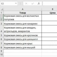
As a result, a new layer will be created (added) in AutoCAD with standard settings. You will now be prompted to enter his name. By default, layers are named "Layer1", "Layer2", etc. However, I recommend giving layers more meaningful names. For example, "axes", "external walls", "partitions", "windows", "doors", etc.

Layer Manager in AutoCAD. Basic layer properties
So, we figured out how to open the "Layers" window in AutoCAD 2015, and also examined in detail how to create a new layer. Now let's find out what the AutoCAD Layer Manager contains and what properties can be assigned to grouped objects.
For any layer, you can adjust the color, line type and thickness (line weight). This will allow simultaneously all objects lying on a particular layer to assign these properties once.
1) One of the most frequently asked questions is "How to change the color of a layer in AutoCAD?" To do this is quite simple: you need to click on the box that is visually responsible for the color of the layer, after which a palette will open to select the desired color, as shown in Fig. 3.

2) In practice, there is also such a question "How to change the thickness of the AutoCAD layer?" The "Lineweight" column is responsible for this. Read more about this property in the article " ".

How to edit layers in AutoCAD?
Editing layers in AutoCAD involves changing certain properties that were previously assigned to the layer. It can be color, type and weight of lines. It is often necessary to rename a layer because There may be a typo in the beginning. So, any changes should be made in the AutoCAD Layer Properties Manager, which is called as shown in Fig. one.
Earlier we looked at how to change the properties of layers, let's take a closer look at how to rename a layer in AutoCAD? Open the Layer Properties Manager dialog box.
To rename a layer in AutoCAD, double-click (with a short interval) the left mouse button on the layer name.
The layer name will now be editable. Enter a new layer name. Close the dispatcher when finished.
The layer name can contain up to 255 characters: letters, numbers, and a few special characters. By the way, you can put spaces in the AutoCAD layer name, but such characters< >/\" : ; ? * | = ' cannot be contained in a title.

Very often in the AutoCAD system, you need to change the color of an object, the thickness and type of lines. True, constantly changing line parameters when drawing either one object or another is not the most productive task.
For the convenience and efficiency of work in the AutoCAD system, the use of so-called layers is provided. Therefore, let's take a closer look at what a layer is in the AutoCAD package and what it is for.
Each layer in AutoCAD is a transparent sheet of paper on which certain objects are drawn, for example, only external or internal load-bearing walls, partitions, windows, etc.
When layers are superimposed on each other, the final drawing is obtained. And you can create the required number of layers.
Working with layers in AutoCAD 2015 is carried out using the Options Manager and special commands.Here are a few things you can do with layers:
① Each layer in AutoCAD can be given its own personal name.
② For each layer, you can set your own color, type and line thickness.
③ Any of the layers can be made visible or invisible.
④ You can set your own print settings for each layer. 
Thus, working with layers in AutoCAD gives a lot of advantages. Those. you can group objects of the same type on separate layers.
Also, each layer can be assigned its own drawing parameters (type, color and line thickness), which will be used automatically when selecting a layer.
You can instantly change drawings. For example, by making the layer with partitions invisible.
The list of layers available in the drawing is available on the tab "Home" in a group "Layers".

What is a zero layer in AutoCAD?
By default, a zero layer is created in AutoCAD for new drawings (AutoCAD layer "0"). It is designed to ensure that each project contains at least one layer. Layer "0" cannot be deleted. It also cannot be renamed.
All other layers in AutoCAD you create and configure yourself.
As practice shows, it is convenient to create AutoCAD blocks on the zero layer. This is due to some feature of cleaning the drawing after blocks.
What is the defpoints layer in AutoCAD for?
Defpoints is an AutoCAD utility layer that appears automatically in a drawing when at least one dimension is added. This layer is responsible for the handles for binding dimensions to AutoCAD objects. This layer cannot be deleted or renamed. Therefore, when working in the program, do not pay any attention to it.
How to use layers in AutoCAD?
Let's see in practice how AutoCAD layers work. As an example, open a drawing from a folder C:\Program Files\Autodesk\AutoCAD 2013\Sample\Sheet-Sets\Manufacturing. This folder contains sample drawings that are placed on your computer when you install AutoCAD.
I will open the drawing "VW252-02-1000.dwg".
View the list of layers it contains. In the list, find the "Dimentions" layer (translated from English. "dimensions") and click on the light bulb image in front of the layer name. As a result, the light bulb seems to "go out".
Now click anywhere in the workspace outside of the list of layers. What changed?


Novice users often wonder how to create a layer in AutoCAD?! This is not surprising, for each type of line in autocad you need to create a layer, this program has such a feature. Working with layers in AutoCAD causes a lot of errors when drawing up and printing a drawing. In this lesson, we will take a closer look at how to create a new layer in AutoCAD and how to edit the system layer.
How to create a layer in AutoCAD
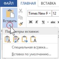
Layers in AutoCAD are very important, so in the top panel of the main tab, in the most prominent place, there is a whole section related to their creation and management.
Conventionally, the "Layers" section can be divided into 3 components: 1 - Layer properties, including the settings of the current layer and the creation of new ones, 2 - Selecting the current layer, 3 - Controlling the current layer.
Let's create a new layer. To do this, click "Layer Properties". A window opens, now it contains only the system layer with the name 0, it cannot be renamed, but each new layer can be called by any name. A green checkmark means that this layer is currently active, you can switch to another layer by double-clicking the left mouse button.

Click the "Create Layer" button. When you hover over this button, a hint of "hot" keys pops up, so you can create it either by clicking the button with the mouse or by pressing Alt + D. The list of layers is updated, the new layer is initially named layer 1.

Rename if you wish. The ability to turn it on and off allows you to hide objects and prevent drawing on the selected layer until it is turned on again. Freezing allows you to hide layers to make the drawing easier to read, as well as to speed up your work. Layer locking does not hide drawing elements and allows you to create new objects when the current layer is selected, but it prohibits editing (deleting, trimming and extending lines, resizing, etc.)
Separately, it is worth highlighting the ability to set the color of the lines for each layer. This is very convenient and allows you to visually divide the drawing into components. To change the color, click on its name.

Select, confirm and the color is changed.
The next important layer step is the line type and weight. In the system layer, a thin line with a weight (thickness) by default. Often it is necessary to create basic lines, thin, axial, dashed, dotted and others. The number of line types in the drawing must match the number of layers created. Let's start with line types.

Click on the name of the line type, in the window that opens, select "Download".

For convenience, the program shows the image and the name of the line. Select the desired line, confirm, a new line with the name of the selected line type will appear in the "Select line type" window, select it, click "OK".
The weight of the line is assigned according to the standards of design documentation and must correspond to its type.

The layer transparency value is entered manually, it can be set from 0 to 90. The print style is not editable, this is an information field. The "Print" button, with the image of a printer, allows you to disable printing of the selected layer. Freezing on new viewports, respectively, is only responsible for additional viewports. In the "Explanations" field, if necessary, a comment is written.
We looked at creating and editing a layer. Before printing a drawing, you need to make sure that all the necessary layers are enabled for printing, and those that are not needed are disabled. In the following lessons, we will look at how to quickly transfer objects from one layer to another, isolate, merge, copy layer properties, and much, much more.
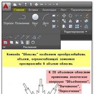
Programs for drawing, animation and three-dimensional modeling use the layered organization of objects placed in the graphic field. This allows you to conveniently structure elements, quickly edit their properties, delete or add new objects.
A drawing created in AutoCAD, as a rule, consists of primitives, fills, hatches, annotation elements (dimensions, texts, marks). The separation of these elements into different layers provides flexibility, speed and clarity of the drafting process.
In this article, we will look at the basics of working with layers and their correct application.
Layers are sets of underlays, each of which has set properties corresponding to objects of the same type located on these layers. This is why different objects (such as primitives and sizes) need to be placed on different layers. In the course of work layers with objects belonging to them can be hidden or blocked for convenience of work.
Layer properties
By default, AutoCAD has only one layer called "Layer 0". The remaining layers, if necessary, are created by the user himself. New objects are automatically assigned to the active layer. The Layers panel is located on the Home tab. Let's consider it in more detail.

"Layer Properties" is the main button on the layers panel. Click it. The layer editor will open in front of you.

To create a new layer in AutoCAD, click the "Create Layer" icon, as in the screenshot.

After that, you can set the following parameters for it:
Name. Enter a name that will logically match the content of the layer. For example, "Objects".
On/Off Makes the layer visible or invisible in the graphics field.
To freeze. This command makes objects invisible and uneditable.
Block. Layer objects are present on the screen, but they cannot be edited or printed.
Colour. This parameter sets the color in which the objects placed on the layer are painted.
Line type and weight. This column sets the thickness and type of lines for layer objects.
Transparency. Using the slider, you can set the percentage visibility of objects.
Seal. Set whether or not to print the elements of the layer.
To make the layer active (current) - click the "Set" icon. If you want to delete a layer, click the "Delete layer" button in AutoCAD.

In the future, you can not enter the layer editor, but manage the properties of the layers from the "Home" tab.
Assigning a Layer to an Object
If you have already drawn an object and want to transfer it to an existing layer, simply select the object and select the appropriate layer from the drop-down list in the layers panel. The object will take all the properties of the layer.

If this does not happen, open the properties of the object through the context menu and set the value "By layer" in those parameters where it is required. This mechanism ensures both the perception by objects of the properties of the layer, and the presence of objects of individual properties.
This article will focus on the use of layers in autocad. How to use layers in autocad. Which layers are better to assign and what are the layers in the autocad program for.
What are layers in autocad.
Layers in AutoCAD serve to group those elements that we draw by line thickness, color and type. You can create as many layers as you like and give each layer its own meaning. In this case, layers can be suppressed (make all elements of the layer invisible), blocked (prohibit selection), and also set properties for printing (print the layer or not).
How to create and edit autocad layers.
When you start working in autocad from the very beginning, creating a new dwg file without using drawing templates, you will find only one layer. This layer is referred to as "0". The zero layer is created by the program by default (so that there is at least some layer) and cannot be deleted.
To draw a drawing correctly in AutoCAD, one layer will not be enough for you. Therefore, it is best to open a ready-made dwg file with ready-made layers. If you just installed autocad and don't have a file for the template, then you should create the necessary layers again.
To do this, find the following menu and click the button to configure layers.
In the AutoCAD window that appears, click the icon to create a new layer. We name the layer as we want it to be clear. 
Now the newly created layer should be given a line weight (printing thickness). 
We will also set the color for the layer in autocad. Choose the colors you like. But keep in mind that if you change the screen background color from light to dark, or someone opens your file on their computer with a different screen background, the layer colors may not please you and your drawing will not be visible very well. 
Let's set the type of lights for our layer. It can be a solid, dash-dotted or dashed line. In the window that appears, click Download. 
Let us choose one of the available line types. There are plenty of them. 
This way we can create as many layers as we want. The thickness of the lines when printed is called the lineweight. For the main lines of the contour, it is usually sufficient to set 0.8 mm. For thin lines, set 0.3 mm. 
This is how the part looks like if you spread its elements to the necessary layers. That is, when drawing detailing for each type of line, we must have a separate layer, that is, a separate layer for hatching, another layer for axial, a separate layer for contour lines, and so on. 
At the bottom there is an icon for displaying the thickness (lineweight). 
This is what the part will look like if you turn on the display of line thickness. 
And this is how the part will look when printed (in monochrome style). 
After creating the layers, select one of them. This will be the current layer. All newly drawn elements will have the parameters of this layer. Also, if you select any elements in the drawing, you can transfer (change) their layer.

However, the parameters of any drawing element, such as color, line weight, or line type, can be changed regardless of the layering. But I do not recommend doing this (so as not to get confused later). In order for the line parameters to correspond to the layer, these parameters must be specified by layer.

Another important advantage of using layers is that layers can be suppressed or frozen. To do this, click on the icons of the light bulb of the sun or the lock opposite the corresponding layer. So in one click, all lines that are on the same layer become invisible or blocked (when they cannot be selected).

This is how boring the drawing would look if we did not use layers. 
What is the best way to use autocad layers.
We were convinced of the need to use layers. Now let's talk about which layers are better to create. (here I write from the point of view of engineering drawings)
The following layers are enough for detailing: main, axial, dotted, hatching and thin line. Create separate layers for dimensions and text as well. That is, for each type of line we create our own separate layer.
For assembly drawings, this rule should not be used. In assembly drawings, we create layers corresponding to the structural nodes and name them accordingly. We also use blocks.
For everyone who works in autocad, the use of layers is the norm, and does not raise big questions.