Amateur radio for RA3LE has been and remains the main component of the part of life that is given to a man in the family for his favorite hobbies or activities. And it began in 1956, with the first complex receiver. It started once and for all. Already in 1958, the first radio station was built on the range of 38-40 MHz, a year later the call sign RAZLAG was received, and soon the first diploma for 4th place in the republican competitions.
After graduating from the Kharkov Polytechnic University in 1965 with a degree in radio engineering, I skipped changing the band to 28-30 MHz without hesitation and switched to VHF. With the new call sign UA3LBO for the All-Union competitions in 1966, he made good equipment using 6S17KV, GS4V / GS6V lamps and antennas of his own design. The result - 3rd place at 144 MHz in the individual standings, and in 1968 - 2nd place in the team standings, which allowed him to receive the title of master of sports. Then there was a break for the period of service as an officer in Lyakhovichi.
The seventies of the last century - a wonderful time for the construction of high-quality equipment and antennas, the beginning of active work through the "Tropo" and "meteors" (MS), the first victories in the "Field Days" and other competitions in radio communication on VHF. Every three years I made a new transceiver and antenna system. By 1981, there were 8 × 13 elements at 144 MHz and 16 × 25 elements at 432 MHz with a BFT66 LNA; "below" - power amplifiers on GI7B and GS31B, respectively. At 1296 MHz - 4 × 37 elements, LNA and power amplifier on GI41B. All these designs were of our own design, but, of course, the experience of foreign radio amateurs was taken into account in the design.
All these years, my main and constant "on-air" companions were George, UC2AAB (now EU1AB), and Victor, RA3YCR. On VHF at that time, Tula people were active in the "east", and Dnepropetrovsk people were active in the "south". Honor and praise to them. Muscovites, as now, were heard infrequently. By this time, I had records for the range of VHF radio communications in Europe and the USSR, for a long time - the first places in the "table of ranks" on all bands in the USSR and at 432 MHz in the European TOP list. I was the first in Russia to start working on 432 MHz with a reflection of signals from the Moon (EME), and QSOs via Aurora in this band became as familiar to me as on 144 MHz.
Since 1985, I have begun to simplify antenna systems, reducing the number of antennas, but improving their quality, because. gradually accumulated experience in creating such systems. During this time, seven antenna systems have been replaced. When calculating and designing antennas, I adhere to the rule - to design high-performance antennas that have maximum gain at the best gain / band ratio (G / T). The bandwidth margin should compensate for the influence of weather conditions in the place of residence. My antennas have never let me down. Perhaps one of the few I work with transceivers of my own design, made by myself.
In some periods there were also declines in activity on my part, caused by circumstances, some "satiation" and a small number of new correspondents in new squares. In addition, since 1983 I stopped working on MS and EME "skedas" - I simply became uninteresting. Many, on the contrary, began to work exclusively on "skeds". Who likes what. After all, many radio amateurs like to work with weak equipment within the region or even EME (at someone else's expense). The complete dependence of work on the air from the Internet and the phone is also not for me.
Since 2004, I again began to work actively in Russian competitions. Experience, high-quality equipment and antennas allowed me to win or take prizes more than once. Two Cups of Russia are very valuable for me. The most interesting for me were and remain connections through Tropo and Aurora. It is a pity that in recent years the Aurora has become a rarity in the middle latitudes.
Everyone goes his own way, depending on knowledge, opportunities and conditions. But still, real satisfaction from doing our favorite thing can only be obtained with good equipment and antennas, which we must constantly strive for.
We bring to your attention antennas for the bands 144, 432 and 1296 MHz— they are simple, have high parameters and good repeatability. However, it does not make sense to describe in detail the design of antennas, because only one in ten radio amateurs will have exactly the same materials and tools for their manufacture. It is enough to describe the requirements for the manufacture of antennas, and the radio amateur himself will select everything necessary for these requirements, otherwise endless questions will begin: “What if ....?”.
The main parameters of the described antennas are given in Table 1, and all the necessary physical dimensions of the antennas for the 144, 432 and 1296 MHz bands are given in Table 1, respectively. 2-4.

The MM AN A program is a handy tool for the antenna designer, but theoretical background is required. When calculating models, they must be checked and corrected - to achieve the best G / T - in other programs, for example, in YA354. Numerous experiments and measurements on professional equipment allow us to conclude that with the selected element diameters, the calculated frequencies in MMANA correspond to the following actual frequencies: 144.6 MHz - 144.3 MHz, 435.0 MHz - 432.0 MHz, 1307.0 - 1296 .0 MHz.

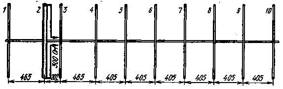
All elements of the 144 MHz band antenna are made of tubes with a diameter of 6 mm. Active vibrator - loopback. Its length is 940 mm, width - 73 mm, and the total perimeter - 2026 mm.


The antennas in the 432 MHz and 1296 MHz bands use simple "split" active vibrators with a diameter of 6 and 2.5 mm, respectively. The remaining elements of the 432 MHz band antenna are made of tubes (rods) with a diameter of 5 mm, and the antenna elements for 1296 MHz are 2.5 mm. The deviation in the values of diameters and lengths of elements for 144 MHz antennas should not exceed ± 0.5 mm, 432 MHz - ± 0.2 mm, 1296 MHz - ± 0.1 mm.
In the 1296 MHz antenna, a reflector is used, two elements of which are vertically spaced up and down by 29.5 mm relative to the plane of the active vibrator and directors.
The elements are attached to the metal traverse at a distance of at least 0.6 from the diameter of the traverse. Homemade or purchased plumbing "clips" are suitable for fastening.
The metal parts of fastening elements to them (clamps, brackets, "self-tapping screws") should not be massive, i.e. significantly increasing the diameter of the elements themselves. On the "clips", mark the center and make a groove for laying the element. When using dielectric (wooden) traverses, any method of fastening the elements (including through the traverse) is acceptable. After assembling the antenna, wooden traverses must be painted with white paint PF115.
The recommended diameter (section) of the traverse for 144 MHz antennas is 25-30 mm, 432 MHz - 18-20 * mm, 1296 MHz - 10-15 mm. The best material is D16Tit.p. When using wooden traverses of such dimensions, elements must be fastened.
In antennas at 432 MHz and 1296 MHz, active vibrators must be located exactly in the plane of the remaining elements, otherwise a vertical radiation angle will appear. In a 144 MHz antenna, the active vibrator must be symmetrical to the plane of the vibrators. It is desirable to make vibrators from copper - this will allow soldering to them coaxial cable along the shortest path, without additional petals, screws, nuts, etc. If a radio amateur knows how to solder aluminum, then in the antennas of the 144 and 432 MHz bands, active vibrators can be made of aluminum. Place rations should be painted with paint PF115. The dimensions of the active vibrators shown in the tables are their finished dimensions!
In antennas in the 144 and 432 MHz bands, copper, D16, AD, aluminum, bimetal can be used to make directors, and in antennas at 1296 MHz, a PEV wire or aluminum (soft!) Wire from household electrical wiring. Avoid transverse scratches on elements.
In antennas in the 144 MHz and 432 MHz bands, the method of fastening active vibrators does not differ from the fastening of directors. Between the halves of the active vibrators of the antennas in the ranges of 144 MHz and 432 MHz, the gap is about 10 mm when connecting a cable with a diameter of not more than 11 mm along the outer insulation. To improve the rigidity of the active vibrator in the place of its cut, you can install a twig made of caprolon or from a fishing rod. In the 1296 MHz antenna, the gap between the halves of the active vibrator should be no more than 6 mm.
In the author's version, the active antenna vibrator at 1296 MHz is attached as follows: the halves are inserted from the sides into a rectangle of polyethylene foam. Transition length central vein cable is 1 mm, the second half of the vibrator is soldered end-to-end to the cable sheath, cut at an angle of 45 °.
I recommend using adapter cables in any VHF antennas. They will allow you to accurately measure / adjust the input resistance and are at the same time a balancing device such as a glass (stocking). The length of the adapter cable from the end of the braid at the active vibrator to the body of the connector soldered at the other end of the cable is 1/2 wave. Almost from the end of the braid at the active vibrator, a screen is put on the outer polyethylene insulation of the cable from the same quarter-wavelength cable, taking into account the shortening of the cable, i.e. the length of the stretched additional braid for the 144 MHz band is 344 mm, 432 MHz - 114 mm, 1296 MHz - 38 mm. The end of the braid of the active vibrator is isolated from everything, and its other end should be connected (soldered) to the main braid of the adapter cable. The resulting design should be placed in a heat shrink tube or carefully wrapped with electrical tape.
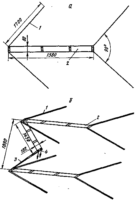
It is possible to place antennas of two polarizations on one traverse by shifting the elements of each antenna by 50-70 mm from each other. Antennas are switched using a relay installed directly on the antenna.
If the antennas are on the bands 144, 432 and 1296 MHz. will be installed on one mast, and the height of the mast is no more than 6-8 m from the conductive surface, then the top should be a 144 MHz antenna, 1.5 m lower - a 432 MHz antenna, 1 m lower - 1296 MHz.
When checking and adjusting the input impedance, it is enough to install the antenna vertically on the table at a height of 1-1.5 m from the ground.
In conclusion, I recommend that you study other sources on this topic before making antennas. They contain suitable tips and recommendations that you can use if they do not contradict the information provided in this article.
You can download the file of described antennas for the MMANA program
Antenna designs are described, as well as schematic diagrams of antenna amplifiers for a home-made VHF radio station (diagram and description) for the frequency bands 144MHz, 430MHz and 1296MHz.
About the characteristics of VHF antennas
The effectiveness of the antenna is uniquely related to its geometric dimensions, for this reason the antenna is the only device that is part of the radio station, which has not been touched by the process of miniaturization of radio equipment.
The manufacture and installation of an antenna is a rather complicated and time-consuming task, especially since it is necessary to solve the issues of strength and rigidity of mechanical structures. However, increasing the efficiency of the antenna is the only unrestricted way to increase energy potential radio stations.
Any antenna can be represented as an equivalent area standing in the way of radio waves propagation. The larger its area, the greater the antenna gain, the formula:
where G is the antenna gain with respect to the isotropic radiator; S - equivalent area, m2; lambda - wavelength, m.
From the point of view of energy, it does not matter what shape the equivalent platform will have: whether it will be round, square, or will have the shape of an elongated rectangle. In any case, with an equal area, there will be an equal gain. Another thing is the radiation pattern; the shape of the equivalent platform has the most direct influence on it. So, the width of the main lobe of the radiation pattern can be related to the linear dimensions of the site by the following approximate expression (formula):

A0(delta_0) - width of the main lobe at the level of -3 dB; hail; lambda - wavelength, m; l- linear size equivalent area in the plane of radiation pattern measurement, m
This formula, rewritten in a different form, allows us to estimate the dimensions of the equivalent area using the known radiation pattern: l = 50 * lambda / delta_0.
Let, for example, tests of the 432 MHz band antenna show that the beamwidth is 25° in the horizontal plane and 20° in the vertical plane. It is easy to determine that the equivalent area will have a size of 1.4 m horizontally and 1.75 m vertically.
Such estimates are very convenient if it is intended to increase the gain by connecting several antennas into an antenna array. So, for the example considered, the distance between adjacent floors of the array should be 1.75 m, and between adjacent rows, 1.4 m. At smaller distances, the equivalent areas will overlap and the total gain will be less than the sum of the gains of all antennas
At large distances, gaps will appear between the individual sites. As a result, the overall gain will not increase, but the dimensions of the antenna will unnecessarily increase. In this case, dips appear in the main lobe of the radiation pattern, breaking it into several components.
And although the presence of such gaps can sometimes be useful (for example, if it is necessary to tune out interference, the azimuth of which differs little from the azimuth of the correspondent), in most cases such a radiation pattern makes it difficult to work on the air.
Returning once again to the issue of antenna gain, it should be noted that in the general case, the gain is the product of the directional coefficient and the antenna efficiency (formula):

where K - c.n.d. antennas; n - efficiency antennas. This means that it is not enough to make an antenna large area, we must also be able to manage all the energy incident on a given area, with minimal losses deliver to the consumer of this energy, i.e. to the input of the receiver. (Here and in what follows, we will use the "principle of reciprocity" that is valid for antennas, which indicates the equivalence of the antenna parameters in the receive and transmit modes. Say, the radiation pattern or efficiency does not depend on whether the antenna is used for reception or transmission. This allows each time to choose the most convenient "for reasoning, the mode of operation of the antenna.)
The radiation of electromagnetic energy is associated with the flow of high-frequency current, so the losses in the antenna itself are determined by ohmic losses in the metal elements. Losses in cable lines have a great influence on the efficiency of the antenna-feeder path, which must be taken into account when assessing the energy potential of the radio station. At the same time, it is useful to remember that the antenna-feeder path is used both for receiving and for transmitting, and, therefore, the losses in the feeder will be included in the final result twice.
The table provides brief information about some high-frequency cables that are used in amateur radio practice. The table shows that as the frequency increases, the losses in the feeder increase rapidly.
So, for example, a 20-meter length of cable type RK-75-4-11 (old name RK-1) attenuates the signal passing through it at a frequency of 144 MHz by 2.1 times (3.2 dB), at a frequency of 432 MHz - 3.4 times (5.4 dB), and at a frequency of 1296 MHz - 13 times (11.2 dB). It can be seen that on high frequency bands losses increase to unacceptable values.
In addition, data are given here for the case when there are no reflections at the ends of the line, i.e., for the case of operation for a matched load. If the load resistance differs from the wave resistance of the cable, then part of the energy is reflected from the end of the cable and moves in the opposite direction.
This reflected portion of the energy can only be returned to the load after it travels a double path from the load to the generator and back from the generator to the load. If the losses in the feeder are small, then such multiple reflections are quite acceptable.
This “tuned feeder” mode is used in particular in some types of multi-band HF antennas. At VHF, where losses in the feeder increase sharply, it can be assumed that part of the energy reflected from the load is almost completely lost. The situation, however, is not as bad as it might seem at first glance. In order to estimate mismatch losses, we write down the c.r.v. as a function of the reflection coefficient (formula):

here Г is the reflection coefficient;

from here it is easy to obtain an expression for calculating the magnitude of losses (formula):

Rice. 31. Technical and wave parameters of coaxial cables.
This expression in graphical form shown in fig. 32. It can be seen that even at r.v.=3, the losses reach only 25%. If the losses in the feeder itself are not very high, then due to the partial return of the reflected energy, the reflection losses will be even less.
So, for the case of losses in the feeder of 2 dB, the loss for reflections at r.m.s. = 3 decreases from 25 to 20%. It can be seen that there is no point in striving for the k.r.v. \u003d 1.1 or even 1.01, cap is given in the description of some amateur radio antennas. Thus, for a r.m.s.w. = 1.5, the loss in reflection, even in the worst case, will be only 4%. It also follows from this that without much loss it is possible to feed an antenna with an input impedance of 50 ohms using a coaxial cable with a wave impedance of 75 ohms, since in this case the r.s.v. will equal 1.5.

Rice. 32. Dependence of losses on reflection from k.s. V.
Let us now consider the features inherent in the antenna-feeder system in the receive mode. In this mode, the noise properties of the antenna begin to play a significant role. For this reason, the concept of noise temperature is often introduced for a receiving antenna. If, for example, the noise temperature of the antenna is 200 K. then this means that the antenna generates the same noise that it generated
would be an active resistance heated to a temperature of 200K. Antenna noise is the sum of external and internal noise. External noise is the source of interference, which fundamentally limits the ability to receive weak signals.
With an antenna directed at the horizon, these are primarily thermal noises of the earth's surface, various kinds of industrial interference, as well as noises of cosmic origin. Internal noise is determined by the presence of losses in the antenna and feeder. Like any active resistance, loss resistance generates thermal noise.
For this reason, the sensitivity of the receiver deteriorates not only due to the attenuation of the received useful signal in the feeder, but also due to the fact that the feeder generates additional noise. Both of these factors are taken into account in a simple formula “for an attenuator heated to ambient temperature. The noise figure of the receiver, taking into account the losses in the feeder, is (formula):

where Ftot is the resulting noise figure; L - attenuation in the feeder or in any other passive quadripole; Fpr is the intrinsic noise figure of the receiver.
Thus, knowing the noise figure of the receiver and calculating the attenuation in the feeder using the table, one can easily determine the resulting noise figure of the receiver from the side of the antenna terminals. You can also solve the inverse problem, that is, by measuring the noise figure with and without a feeder, determine the losses in the cable. This is a more reliable way, since for various reasons, the real losses in the cable can differ significantly from the tabular ones.
It can be seen that the losses in the feeder have a significant impact on the potential of the radio station. As a result, the effort involved in fabricating a large and complex antenna can be negated. And if in the transmission mode it is still possible to somehow compensate for the losses in the feeder by increasing the power, then in the receive mode the losses are irreversible. Antenna preamplifiers located in close proximity to the antenna help to solve this problem.
The question of the need to use such an amplifier must be decided in each specific case, comparing the external noise of the antenna and the internal noise of the receiver. In order to ensure normal operation input circuit receiver, instead of the antenna it is necessary to connect a resistor, the resistance of which is equal to the characteristic impedance of the feeder.
If even during the most favorable night hours the antenna noise noticeably (2 times or more) exceeds the noise of the resistor, an antenna amplifier should not be used. Moreover, the extra amplification stage will make the receiver more vulnerable to interference from nearby radio stations.
In order to connect the preamplifier in the receive mode, you need to have two high-frequency relays or one relay and a separate feeder connecting the preamplifier output to the receiver input.
VHF antenna preamplifier circuits
Antenna preamplifier circuits can be borrowed from the circuits of the corresponding ranges of transverters. For an example in fig. 33, a shows the antenna amplifier circuit for the 144 MHz band, and in fig. 33.6 - for the 432 MHz band.
The tuning procedure for the preamplifiers is the same as the tuning procedure for the corresponding transverter stages.
If the antenna relays do not provide sufficient isolation, the problem arises of protecting the preamplifier from the transmitter signal. As one of the protection measures, diodes D1 are included in the base circuit of the transistors. When setting up, be sure to check whether the connection of the protective diode worsens the noise figure of the preamplifier.

Rice. 33. Antenna amplifier circuits.
Protection problems completely disappear if a powerful multi-emitter transistor KT610 or KT911 is used as a preamplifier. A diagram of such a preamplifier, designed for the 144 MHz band, is shown in fig. 34. Coil L1 contains two turns of silver-plated wire with a diameter of 1.0 mm.
Mandrel diameter - 10 mm. Setting up the amplifier must begin with setting the transistor mode according to direct current. By selecting the resistor R1, it is necessary to ensure that the collector current of the transistor is 15-25 mA.

Fig. 31. Antenna amplifier range of 144 MHz, made on a multi-emitter transistor.
The preamplifier has the following characteristics: gain about 20 dB, noise figure 1.5-1.8. To prevent failure of subsequent amplification stages, it is desirable to remove the supply voltage from transistor T1 in the transmission mode, and even better, connect the preamplifier power wire to ground.
VHF Antenna Designs
Let us now consider some practical antenna designs. For many years, the most popular among radio amateurs have been "wave channel" antennas, which are also known as; "director antennas" and "Uda-Yaga antennas". These antennas, belonging to the class of axial radiation antennas, have the best gain-to-mass ratio and are also very simple in design.
The main disadvantage that has limited the use of such antennas in industrial communications is the narrow band. However, for radio amateurs, this disadvantage does not play a big role, since the width of the ranges allocated for amateur radio communications is also small.
Recently, numerous attempts have been made to improve the wave channel antenna in order to increase its gain. As an active element, a segment of a log-periodic antenna was used (an antenna of the “Swan” type) or more complex passive elements were used, consisting, for example, of four half-wave vibrators (numerous types of antennas produced by Western countries for receiving television on decimeter waves).
However, all these tricks do not give a significant gain, since in the end the gain of any antenna with axial radiation is determined by its length. The use of more complex vibrators is equivalent to the use of several conventional "wave channel" antennas located at a very small distance from each other. As already mentioned, this is equivalent to almost complete mutual overlap of equivalent areas, and therefore, the resulting gain is also small.

Rice. 35. An eight-element Quagi antenna for the 144 MHz band, dimensions for the 432 MHz band are given in brackets.
Of the advanced "wave channel" antennas, perhaps the most interesting are the "Quagi" type antennas. The name is composed of two English words "Quad" and "Yagi" and indicates that the antenna is a hybrid of the "square" and "Yagi" antennas.
Actually, only the active element and the reflex frame are taken from the "square", and all directors are the same as in the "wave channel" antenna. The antenna is powered by a cable with a wave impedance of 50 ohms. The cable is connected directly to the break of the active frame without any matching device.
The reflex frame has a perimeter of 2200 mm (711 mm), while the active frame has a perimeter of 2083 mm (676 mm). Here and below, in parentheses, the dimensions for the 432 MHz band are indicated.
Both frames are made of copper wire with a diameter of 2.5-3 mm and are fixed to the carrier traverse using organic glass strips. The bearing traverse has a length of 420 cm (140 cm) and is made of a wooden, preferably pine, bar with a section of 2.5X8 cm (1.2x5 cm). To facilitate the construction, the height of the bar can be reduced towards the ends of the antenna. The directors are made of aluminum or copper wire with a diameter of 3 mm.
The output impedance of the antenna is 50 ohms, however, without large losses it can be powered by a cable with a characteristic impedance of 75 ohms. When using multiple antennas, the distance between adjacent floors and rows should be 3.35 m (1.09 m).
A similar design has a more efficient Quagi antenna designed for the 432 MHz band. The bearing traverse is made of a wooden bar 370 cm long and 2.5x5 cm in section. The height of the bar gradually decreases towards the ends to 1.5 cm.
The length of the reflex frame is 711 mm, and the active frame is 676 mm. Both frames are made of copper wire with a diameter
2.5 mm. The directors are made of wire with a diameter of 3 mm. Other dimensions are shown in fig. 36.
The antenna is powered by a coaxial cable with a wave impedance of 50 ohms without a balun. In principle, this antenna can be used for the 1296 MHz band, while the wire diameter and all other dimensions should be reduced by a factor of 3.

Rice. 36. Fifteen-element Quagi antenna for the 432 MHz band.
Of the antennas specially designed for the 1296 MHz band, the antenna proposed by the British ultrashortwave G3JVL is of interest. The antenna is a "wave channel" with ring vibratos
ramie, a kind of multi-element loop antenna. The antenna contains 28 elements, including an additional aluminum mesh reflector and 27 ring vibrators. The main reflector and all directors are made of aluminum strips 4.8 mm wide and 0.7 mm thick.
Holes for the M3 screw are drilled at the ends of the strips. The hole center distance is 246 mm for the reflector, 210 mm for the first 11 directors, and 203 mm for the remaining directors. Then the strips are rolled into a ring and screwed to a carrier duralumin tube with a diameter of 12-15 mm. The distances between the elements are shown in fig.
37. The dimensions of the additional reflector are shown in fig. 38, a.
Rice. 37. Twenty-eight-element antenna for the 1296 MHz band, the distances to the elements are counted from the additional reflector.

Rice. 38. Antenna for the 1296 MHz band.
The design of the active element is shown in fig. 38.6. Unlike other elements, the active frame is made of copper strip. Frame perimeter 235 mm.
The frame is attached to the carrier tube with a Mb threaded bolt. A thin cable with PTFE insulation is passed through a hole drilled along the axis of the bolt. In the middle of the strip from which the active frame is made, a hole for the cable is also drilled. The frame is attached to the bolt head by soldering. The cable sheath is also soldered to the bolt head.
A thin cable with increased attenuation should be as short as possible. It ends with a high-frequency connector to which the main feeder is connected. It is possible that the thicker cable is passed through the fixing bolt, but through a hole drilled in the carrier tube behind the active frame.
In this case, it is also necessary to ensure contact of the cable sheath with the base of the frame.
In the above descriptions of antennas, data on the gain are deliberately not indicated. The fact is that the accurate measurement of the antenna gain is quite difficult, requiring special conditions. As a result, various data often appear in amateur radio literature.
So, the figure given by the author of the antenna described above for the 1296 MHz band seems to be somewhat overestimated - 20 dB. The data given for the Quagi antenna looks more realistic - 12 dB for an 8-element antenna and 15 dB for a 15-element antenna.
Zhutyaev S. G. Amateur VHF radio station, 1981.
The broadcast FM band attracts radio amateurs. Free frequencies occupy the region of 145 - 433 MHz, that's where we will show the skills of designing equipment. Do-it-yourself residents of remote villages, who receive the signal uncertainly, undertake to make VHF antennas with their own hands. There are many reasons for the manifestation of independence, it is important to bypass the forbidden areas of transmission - you will not end up with problems.
Conceived engineer friends to broadcast, the law is not prohibited when done without violating government regulations. Assembling the transmitter, setting up the process is a separate problem, each subscriber will need an antenna for VHF.
Amateur range prices bite. Non-standard products are not very popular, it is unprofitable to produce, therefore the cost is high.
145 MHz amateur band
Stationary VHF antennas are relatively easy to manufacture. The basis is the scheme of a quarter-wave vibrator. Band products have a relatively wide bandwidth, fine tuning to the frequency is not required. Consider examples of structures:
- For maximum easy way manufacturing a receiving antenna - outdoors, at home, anywhere - you need a T-tee. The perpendicular branch is supplied with a coaxial, the other two - with a twisted spire of the radio station, counterweights (analogous to the earth of the VHF band).
- A right corner with square sides of 4 cm is attached to the outer wall, counterweights 5 cm long are bolted to the edges of the horizontal platform, and a connector for the antenna is equipped in the middle. Since the coaxial cable branch leading to the structure is the main cause of signal loss, the length of the segment must be kept to a minimum. It will be difficult to make gold connectors on your own, it is necessary to clean the existing steel ones, wipe with alcohol, increasing the sensitivity. Since a standard amateur radio antenna inserted into the socket of the site has an impedance of the order of 40 ohms, the connection is made with a 50 ohm coax. Finally, the wave impedance of the remote antenna is adjusted by turning the counterweights. To replace the factory antenna, you can use a piece of copper wire with a diameter of 1-2 mm, 48 cm long.
- If the original VHF antenna is broken, replace it with a 48 cm piece of 50 ohm coaxial cable with the shield removed. Avoid exposing the vein. You can replace the product with a piece of wire in the previous method.
- We get a more complex version by winding half a meter of copper wire on the internal dielectric of the coax. The difficulty lies in matching the impedance of the resulting homemade design with the wave impedance of the radio station. After debugging, secure the turns with electrical tape.
145 MHz Half Wave Antenna
The quarter-wave homemade VHF antennas discussed above are not the only way out of the situation. The advantage of low impedance, half-wave options have the right to exist. A piece of wire with a diameter of 1 mm, a length of 103 cm has a resistance of 1 kOhm, 20 times higher than a standard coaxial (50 Ohm).
To match the difference in values, a U-shaped contour is used. The future wire antenna should be cut a few centimeters shorter / longer than 103 cm. It will slightly increase the losses due to the growth of the reactive component of the impedance, significantly reducing the real part of the impedance, the matching device will be easier to tune.
The filter inductance is connected in series with the antenna, it is formed by 5 turns of wire 1 mm in diameter, wound with a pitch of 2 mm on a mandrel with a diameter of 6 mm. Trimmer capacitors KPVM-1 (5-14 pF) are switched on with one plate to the ground on both sides of the coil.
The antenna for the VHF radio receiver is tuned by measuring the SWR, field strength. The minimum of the first parameter coincides with the maximum of the second. Otherwise, the length of the antenna is shortened, the measurements are taken again. It is recommended to initially select a wire length of 102 cm, gradually cut from the upper end, choosing the optimal value.
Broadband Antenna
For the manufacture of a stationary VHF antenna with a height of over one and a half meters, tuned to two amateur frequencies, 145 MHz, 433 MHz, you will need dielectric rods with a diameter of 7 - 17.5 mm. The wound turns are fixed with an adhesive composition, a compound. They need to be precisely wound, what has been said will not be a simple matter.
The work is carried out with a solid wire of 2 mm diameter. The direct indent from the top is 38.7 cm, then the dielectric rod with a diameter of 7.5 mm is wrapped with strictly 12.5 turns in increments so that the total height of the inductance is 63 mm. Stepping back 42.2 cm of the straight section, wind 64 turns on a 7 mm rod so that the total height of the inductance is 28 cm. Then - a straight section of 36.7 mm, again turns - 7 pieces (32 mm high) on a 10 mm rod. Finally, the last wire segment, 56.4 cm long, terminates in an inductance formed by 4 turns (20 mm high) over a 17.5 mm rod.
One and a half turns from the top in the last inductance is tapped to the main core of the coaxial cable with a resistance of 50 ohms. A tuning capacitor of 1-10 pF is connected in series to the circuit. The ground of the VHF antenna is connected to the screen. In parallel with the last inductance, a capacitance of 1 pF is switched on for correcting operation at a wavelength of 70 cm.
The bottom of the antenna is equipped with eight counterweights:
- four bands 145 MHz;
- four frequencies 433 MHz.
After assembly, the product is adjusted, guided by the standing wave coefficient, a resistance meter. In both ranges, select acceptable values. Such an antenna, assembled with your own hands, will last a long time if placed in a durable protective case made of dielectric material, protected against moisture with a compound.
The honor of developing a variant of the VHF antenna belongs to Alexander RV9CX. The author advises a capacitance of 1 pF to be performed with a SAT-50 cable segment (2 cm). One winding will serve as a screen, the second - a core. The central wire can be pulled out-inserted back, changing the capacitance of the capacitor.
FM band
It is common for radio amateurs to delve into the element base, assembling complex devices. But a homemade antenna for a VHF receiver will come in handy for the average Mayak fan.
First you will need a 20 cm square board, or an equivalent piece of plexiglass. A square with a side of 15.5 cm is cut out of the foil, a square hole with a side of 11.9 cm is cut inside in the center.
In one side of the concentric figure (square), a cutout is made a couple of centimeters wide, the foil is glued to the board in the center with the slit down. At the intersection of the lower continuation of the right inner side of the square, the middle line of the lower wall of the concentric figure, the wire of the central core of the coaxial cable is soldered. Four centimeters to the left, the wire connecting to the screen is soldered.

The resulting design confidently receives FM broadcast stations.
Applicability of homemade antennas
Homemade antennas HF-VHF are quite popular. Unlike complex transceiver equipment, where undisputed leadership goes to factory products, a wire structure, when properly tuned, gives excellent results.
The instruments required for parameter evaluation are rarely available. For the correct operation of a homemade VHF antenna, an SWR meter, a field strength meter, is required. Ultimately, the problem is not in the geometric dimensions of the parts, the relative position, but in matching the impedances of the submarine coaxial cable and the antenna itself.
You can use any methods to fix the problem, it was shown above how to do what was said with the help of resonant circuits. A small adjustment is performed by changing the position of the counterweights; it is difficult to find the necessary parameters empirically. Resonators will rarely best solution due to the associated difficulties of use.
Again and again, ultrashortwavers ask their senior colleagues: "Which antenna should I choose?" It is impossible to answer this question precisely, since it all depends on the purpose for which the antenna is being built. If communications are expected in all directions, for example within a city, then pie antennas are very convenient, which often allow you to work at distances between stations equal to 50-100 km. Directional antennas are more suitable for long-distance communications. In "densely populated" areas with ultrashortwaves or in cases where there is interference from some directions, it is undoubtedly better to use highly directional antennas.
These few examples are enough to understand that there is no antenna that is equally suitable for all cases. The radio amateur must choose an antenna that meets his basic requirements. Better yet, build two or three antennas and use them as needed.
It is unreasonable for a novice ultrashortwave to choose as his first antenna some bulky and complex structure, in the process of building which, due to inexperience, he can make many mistakes. You should start with the construction of the simplest antennas and, as experience and knowledge grow, move on to more complex systems.
When choosing the type of antenna, one must also take into account what basic materials are available to the designer. If it is not possible to purchase pipes or rods for the antenna elements, then you can choose, for example, a "double square", which requires only wire, wooden slats and a small amount of insulating material to build. It is also essential how the supply line will be made - from a coaxial or ribbon cable, or simply in the form of a two-wire line.
We must not lose sight of whether any measurements are needed when building an antenna. For a beginner, who also does not have measuring equipment, it is better to choose an antenna that will probably work well without tuning.
Consider a number of types of antennas. Among them there are simple designs that can be repeated by every beginner, and complex ones, including antenna systems, that may be of interest to more experienced DX hunters. Since most of our VHFs operate in the 144 MHz band, antenna dimensions are given for this band.
The reader will note that no technical details of construction are given for any of the antennas. But this should not interfere with the construction, since the methods of work and many details are described in any ham radio handbook.
CIRCULAR RADIATION ANTENNAS
Cross dipole. The antenna consists of two half-wave vibrators 1 located at an angle of 90° to each other (Fig. 1). The radiation pattern of this antenna is far from being a perfect circle, but in practice it gives quite good circular radiation. Since the impedance of one dipole is approximately 70 ohms, when two dipoles are connected in parallel, the impedance is about 35 ohms. We do not have such a coaxial cable at our disposal, so it is best to feed the antenna through a quarter-wave transformer 3, made from a 50-ohm cable. A 75-ohm cable 4 runs from the transformer to the equipment. Balancing U-elbow 2 is made of the same cable.
Vertical antenna (Ground Plane). Emitter 1 (Fig. 2) and radial conductors 2 provide a circular diagram in a horizontal plane. The angle between the radial conductors and the radiator determines the impedance of the antenna.

rice. 2
At an angle of 90 °, the wave impedance is approximately 30 ohms, at an angle of 180 ° - 70 ohms. Typically, an angle of 145° is chosen, which allows the antenna to be fed with a 50-ohm cable. The cable is connected to connector 3, mounted on a metal plate, to which radial conductors are electrically connected. The emitter, to which the central conductor of the cable is connected, is installed on insulator 4.
DIRECTIONAL ANTENNAS
"Double Square" This most popular directional KB antenna is also usable on VHF (Fig. 3, a). Its gain (compared to a half-wave vibrator) reaches 5.7 dB, the ratio of radiation forward / backward is 25 dB.
rice. 3
The distance between the active vibrator 1 and the reflector 2 is chosen to be 0.15 lambda, which makes it possible to feed the antenna with a 75-ohm coaxial cable 3. Experience has shown that the antenna fed in this way works quite satisfactorily. You can tune the antenna using a short-circuited loop included in the break in the reflector frame.
To balance the antenna, you can use a quarter-wave glass (Fig. 3, b), connecting it to the ends of the active vibrator 1. The glass consists of a metal cylinder 4 with two covers - metal 5 and dielectric 6. Cable 3 passes inside the glass, the cable braid is connected to the cover 5. The diameter of the cup should be 3-4 times the diameter of the cable.
For the manufacture of antenna elements, you can use a copper or aluminum tube, tape or wire of various diameters. "Double square" takes up very little space, structurally simple. This antenna is relatively good performance. Noteworthy is the possibility of placing antennas of different ranges on the same cross-shaped rails.
Triangular Antenna (Delta Loop) belongs to the same family as "square", since the perimeter of the active vibrator is approximately equal to the wavelength. A feature of this antenna is that all elements of its design are metal. The author of the antenna advised to feed it with a 50-ohm coaxial cable, but a 75-ohm cable is also successfully used for this purpose. The simplest triangular antenna is shown in fig. 4. Active vibrator 1 is adjusted using a gamma matching device to which cable 3 is connected. Depending on the availability of measuring instruments, the adjustment is carried out according to the minimum SWR or the maximum signal strength. Reflector 2 can be made unregulated for simplicity.

rice. 4
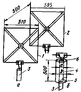
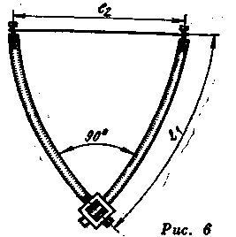
UA1WW experimented a lot with the triangular antenna. He advises using 5- and 9-element options. The latter, due to the small horizontal angle of radiation, is particularly suitable for long-distance communications. A drawing of a 5-element antenna is shown in fig. 5. Here 1 is an active vibrator, 2 is a reflector, 3-5 are directors. Since this is a completely new antenna for our ultrashortwave antennas, here are some design data.
rice. 5
A 4-sided duralumin tube with a square side of 18-20 mm is most suitable for the bearing traverse; it is much more convenient to mount elements on it than on a round tube (see Fig. 6).

rice. 6
Antenna elements are made of a copper or aluminum tube or rod with a diameter of 6 mm, the horizontal side is made of a wire with a diameter of 3 mm. The dimensions of the elements (in accordance with Fig. 6) are as follows:
triangular antenna- an object of interest for ultrashortwaves all over the world. Taking into account the positive experience with it, we can assume that it will soon become one of the most popular antennas. Therefore, we draw the attention of those wishing to experiment to one special type of it - a double triangular antenna (Fig. 7). The dimensions of the triangles of this antenna are slightly larger than those of a single one; the perimeter of the reflector is 2266, the active vibrator is 2116 and the director is 1993 mm. The distance between the reflector and the vibrator is 0.2 lambda, between the vibrator and the director is 0.15 lambda.

rice. 7
According to some data, the following gains of a double antenna were obtained (compared to a half-wave vibrator): one element (active vibrator) - 3-4 dB: two elements (vibrator and reflector) - 8-9 dB: three elements (reflector, vibrator in director), - 10-11 dB. It seems that this is a promising type of antenna and it is worth looking into.
10-element antenna (Yagi). Undoubtedly, this is the most popular VHF antenna (Fig. 8). It gives a gain of 13 dB. The author carried out with the help of such an antenna meteor communications with England and Belgium, many long-distance communications due to tropospheric passage and "Aurora".
rice. 8
The passive elements of the antenna are made of a bimetallic wire with a diameter of 4 mm, and the active loop vibrator is made of a 15 mm copper tube and the same wire. The characteristic impedance at the feed point is 300 ohms, so the 75 ohm cable is connected through a U-bend, which is 68 cm long.
The length of the bearing traverse is slightly more than 3.5 m, the diameter is 20 mm. The length of the reflector 7-1060, vibrator 2-990, directors 3-10 - respectively 933, 930, 927, 924, 921, 918, 915 and 912 mm.
Antenna for multiple bands. There are circumstances when it is not possible to install more than one antenna. But in addition to an antenna, a radio station often needs a television one! Then the way out is a UKB antenna for several bands. One such antenna is shown in Fig. 9, a (top view) and 9, b (axonometric projection). It can be successfully used in the ranges from 50 to 220 MHz. The antenna gain at a frequency of 50 MHz is 7 dB, 144 MHz is 12 dB, and at 220 MHz it is even 13.5 dB. This antenna is double decker. At a frequency of 50 MHz, two corner vibrators 1 operate on each floor, located at a distance of lambda/4. At a frequency of 144 MHz, their length is approximately 3/4 lambda and therefore already a V-shaped antenna is obtained. At 220 MHz, the vibrators are 5/4 lambda long.
rice. 9
The vibrators are interconnected by two-wire lines 2, and both floors - by lines 3, the length of which, depending on the range, is from 1/4 to 5/4 lambda. The distance between the floors, if desired, can be changed within the limits allowed by the length of the lines 3. The input impedance of the antenna at the feed point 4 at frequencies of 50 and 144 MHz is about 300 ohms, at a frequency of 220 MHz it drops to about 200 ohms.
Antenna elements can be made from a tube or rod: vibrators - 10 mm in diameter; lines 2 - with a diameter of 12 mm (10 mm is also possible, then the distance between the centers of the wires of the line should be chosen equal to 64 mm): lines 3 - with a diameter of 6 mm.
RADIO No. 8, 1973 pp.20-23.
A short time ago, home-made equipment was mainly used to work on the 144-145 MHz band. VHF transverters were popular among radio amateurs, many of which were comparable in size to the transceiver itself used with it. Radio amateurs converted decommissioned industrial VHF radio stations of the Palma type to the amateur VHF band of 145 MHz, receiving a radio station operating on several channels. Then the Violas became available to radio amateurs, and later the Mayaks, operating on forty channels. These radios then looked fantastic in their capabilities!
At present, it is relatively inexpensive to purchase multi-channel portable VHF transceivers of world famous companies - YAESU, KENWOOD, ALINCO, which, in terms of their parameters and ease of use, are significantly superior to both home-made equipment in the 145 MHz band and converted industrial equipment - Palma ”, “Lighthouses”, “Violas”.
But to work through a repeater from home, office, while driving when working from a car, you need an antenna that is more effective than the “rubber band” used in conjunction with a portable radio station. When using a stationary "proprietary" VHF station, it is often advisable to use a homemade VHF antenna with it, since a decent "proprietary" outdoor antenna in the 145 MHz range is not cheap.
This material is devoted to the manufacture of simple home-made antennas suitable for use with stationary and portable VHF radio stations.
Features of 145 MHz Antennas
Due to the fact that for the manufacture of antennas in the 145 MHz band, thick wire is usually used - with a diameter of 1 to 10 mm (sometimes thicker vibrators are used, especially in commercial antennas), then 145 MHz band antennas are broadband. This often makes it possible, when making the antenna exactly according to the specified dimensions, to do without its additional tuning to the 145 MHz band.
To tune antennas in the 145 MHz range, you must have an SWR meter. It could be like homemade device, and industrial production. On the 145 MHz band, radio amateurs practically do not use bridge antenna impedance meters, due to the apparent complexity of their correct manufacture. Although, with careful manufacture of the bridge meter and, therefore, its correct operation in this range, it is possible to accurately determine the input impedance of VHF antennas. But even using only an SWR - a pass-through type meter, it is quite possible to tune home-made VHF antennas. The power of 0.5 W, which is provided by imported portable radio stations in the "LOW" mode and domestic portable radio stations of the VHF range such as "Dnepr", "Viola", "VEBR", is quite enough to operate many types of SWR meters. The "LOW" mode allows you to tune the antennas without fear of failure of the output stage of the radio station with any input impedance of the antenna.
Before you start tuning the VHF antenna, it is advisable to make sure that the readings are correct. SWR meters. It's a good idea to have two SWR meters rated for 50 and 75 ohm transmission paths. When setting up VHF antennas, it is desirable to have a control antenna, which can be either an "elastic band" from a portable radio station or a home-made quarter-wave pin. When tuning the antenna, the level of field strength created by the tuned antenna relative to the control one is measured. This makes it possible to judge the comparative efficiency of the tuned antenna. Of course, if a standard calibrated field strength meter is used in the measurements, an accurate estimate of the antenna's performance can be obtained. When using a calibrated field meter, it is easy to take the antenna pattern as well. But even using the measurements homemade meters field strength and having received only a qualitative picture of the distribution of the electromagnetic field strength, it is possible to draw a conclusion about the efficiency of the tuned antenna and approximately estimate its radiation pattern. Consider the practical design of VHF antennas.
Simple Antennas
The simplest outdoor VHF antenna (Fig. 1) can be made using an antenna that works in conjunction with a portable radio station. A metal corner is attached to the window frame from the outside (Fig. 2) or from the inside on an extension wooden bar, in the center of which there is a socket for connecting this antenna. It is necessary to strive to ensure that the coaxial cable leading to the antenna is the minimum required length. 4 counterweights 50 cm long are attached along the edges of the corner. It is necessary to ensure good electrical contact of the counterweights, the antenna connector with the metal corner. The shortened twisted antenna of the radio station has an input impedance in the range of 30-40 ohms, so a coaxial cable with a characteristic impedance of 50 ohms can be used to power it. With the help of the tilt angle of the counterweights, it is possible to change the input impedance of the antenna within certain limits, and, therefore, to match the antenna with the coaxial cable. Instead of the branded "elastic band", you can temporarily use an antenna made of copper wire with a diameter of 1-2 mm and a length of 48 cm, which is inserted into the antenna socket with its sharply sharpened end.
Figure 1. A simple outdoor VHF antenna

Figure 2. Construction of a simple outdoor VHF antenna
The VHF antenna, made of a coaxial cable with the outer braid removed, works reliably. The cable is terminated in the RF connector similar to the connector of the "proprietary" antenna (Fig. 3). The length of the coaxial cable used to make the antenna is 48 cm. Such an antenna can be used in conjunction with a portable radio station to replace a broken or lost standard antenna.
Figure 3. A simple homemade VHF antenna
For quick production of a remote VHF antenna, you can use a connecting coaxial cable 2-3 meters long, which is terminated with connectors corresponding to the antenna jack of the radio station and antenna. The antenna can be connected to such a piece of cable using a high-frequency tee (Fig. 4). In this case, an “elastic band” antenna is connected from one end of the tee, and counterweights 50 cm long are wound from the other end of the tee, or another type of radio technical “ground” for the VHF antenna is connected through the connector.

Figure 4. A simple remote VHF antenna
Homemade portable radio antennas
If the standard antenna of the portable radio station is lost or broken, you can make a home-made twisted VHF antenna. For this, a base is used - polyethylene insulation of a coaxial cable with a diameter of 7-12 mm and a length of 10-15 cm, on which 50 cm of copper wire with a diameter of 1-1.5 mm is initially wound. To tune a twisted antenna, it is very convenient to use a frequency response meter, but you can also use an ordinary SWR meter. Initially, the resonant frequency of the assembled antenna is determined, then, biting off part of the turns, shifting, pushing the turns of the antenna, tune the twisted antenna to resonance at 145 MHz.
This procedure is not very complicated, and by setting up 2-3 twisted antennas, a radio amateur can tune new twisted antennas in just 5-10 minutes, of course, with the above devices. After tuning the antenna, it is necessary to fix the turns either with electrical tape, or with cambric soaked in acetone, or with a heat shrink tube. After fixing the turns, it is necessary to once again check the frequency of the antenna and, if necessary, adjust it with the help of the upper turns.
It should be noted that in the "proprietary" shortened twisted antennas, heat-shrinkable tubes are used to fix the antenna conductor.
Half wave field antenna
For effective work quarter-wavelength antennas, multiple quarter-wave counterbalances must be used. This complicates the design for a field quarter-wave antenna, which must be placed in space relative to the VHF transceiver. In this case, you can use a VHF antenna with an electrical length L / 2, which does not require counterweights for its operation, and provides a radiation pattern pressed to the ground and ease of installation. For an antenna with an electrical length L/2, there is a problem of matching its high input impedance with the low wave impedance of the coaxial cable. An antenna with a length of L/2 and a diameter of 1 mm will have an input impedance on the 145 MHz band of about 1000 ohms. Matching with a quarter-wave resonator, which is optimal in this case, is not always convenient in practice, since it requires the selection of connection points for the coaxial cable to the resonator for its efficient operation and fine tuning of the antenna pin to resonance. The dimensions of the resonator for the 145 MHz band are also relatively large. Destabilizing factors on the antenna, when it is matched with a resonator, will manifest themselves especially strongly.
However, at low powers supplied to the antenna, quite satisfactory matching can be achieved using a P-loop, similarly as described in the literature. A diagram of a half-wave antenna and its matching device is shown in fig. 5. The length of the antenna pin is chosen to be slightly shorter or longer than the L/2 length. This is necessary because even with a small difference in the electrical length of the antenna from L / 2, the active resistance of the antenna impedance noticeably decreases, and its reactive part at the initial stage increases slightly. As a result, it is possible to match such a shortened antenna using the P-loop with greater efficiency than the matching of an antenna with a length of exactly L / 2. It is preferable to use an antenna slightly longer than L/2.

Figure 5. VHF antenna matching using a P-loop
In the matching device, air tuning capacitors of the KPVM-1 type were used. Coil L1 contains 5 turns of silver-plated wire with a diameter of 1 mm, wound on a mandrel with a diameter of 6 mm and a pitch of 2 mm.
Antenna tuning is not difficult. By including an SWR meter in the antenna cable path and simultaneously measuring the level of the field strength created by the antenna, by changing the capacitance of the variable capacitors C1 and C2, compressing and stretching the turns of the L1 coil, the minimum SWR meter readings and, accordingly, the maximum field strength meter readings are achieved. If these two maxima do not match, you need to slightly change the length of the antenna, and repeat its tuning again.
The matching device was placed in a case soldered from foil fiberglass with dimensions of 50 * 30 * 20 mm. When working from a stationary workplace of a radio amateur, the antenna can be placed in the window opening. When working in the field, the antenna can be hung from the upper end on a tree using a fishing line, as shown in Fig. 6. A 50 ohm coaxial cable can be used to power the antenna. Using a 75-ohm coaxial cable will slightly increase the efficiency of the antenna matching device, but at the same time, it will require tuning the radio's output stage to operate at a load of 75 ohms.

Figure 6. Mounting the antenna for field work
Foil Window Antennas
Based on the adhesive foil used in burglar alarm systems, very simple designs of VHF window antennas can be built. Such foil can be purchased already with an adhesive base. Then, having freed one side of the foil from the protective layer, it is enough just to press it against the glass and the foil instantly sticks securely. Foil without an adhesive base can be glued to glass using varnish or Moment type glue. But for this you need to have some skill. The foil can even be fixed to the window with adhesive tape.
With proper training, it is quite possible to make a high-quality solder connection of the central core and the braid of the coaxial cable with aluminum foil. Based personal experience, each type of such foil requires its own flux for soldering. Some types of foil solder well even using only rosin, some can be soldered with soldering fat, other types of foil require the use of active fluxes. The flux should be tested on the particular type of foil used to make the antenna well in advance of installation.
Good results are obtained by using a substrate made of foil fiberglass for soldering and fixing the foil, as shown in Fig. 7. A piece of foil fiberglass is glued to the glass with Moment glue, the antenna foil is soldered to the edges of the foil, the cores of the coaxial cable are soldered to the copper foil of the fiberglass at a small distance from the foil. After soldering, the connection must be protected with a moisture-resistant varnish or glue. Otherwise, corrosion of this connection is possible.

Figure 7 Connecting Antenna Foil to Coaxial Cable
Let us analyze the practical designs of window antennas built on the basis of foil.
Vertical window dipole antenna
The diagram of a vertical dipole window VHF foil-based antenna is shown in fig. 8.

Figure 8. Windowed vertical dipole VHF antenna
The quarter-wave pin and counterweight are angled at 135 degrees to bring the antenna system's input impedance closer to 50 ohms. This makes it possible to use a coaxial cable with a wave impedance of 50 ohms to power the antenna and use the antenna in conjunction with portable radio stations, the output stage of which has such an input impedance. The coaxial cable should run perpendicular to the antenna on the glass for as long as possible.
Foil Loop Window Antenna
More efficient than a dipole vertical antenna, a VHF loop antenna, shown in fig. 9. When feeding the antenna from the side angle, the maximum of the radiated polarization is located in the vertical plane, when feeding the antenna in the lower corner, the maximum of the radiated polarization is in the horizontal plane. But at any position of the feed points, the antenna radiates a radio wave, with a combined polarization, both vertical and horizontal. This circumstance is very favorable for communication with portable and mobile radio stations, the position of the antennas of which will change during movement.

Figure 9. VHF frame window antenna
The input impedance of the window loop antenna is 110 ohms. To match this resistance with a coaxial cable with a characteristic impedance of 50 ohms, a quarter-wave section of a coaxial cable with a characteristic impedance of 75 ohms is used. The cable should run perpendicular to the axis of the antenna for as long as possible. A loop antenna has about 2 dB more gain than a dipole window antenna.
When making window foil antennas with a width of 6-20 mm, they do not require tuning and operate in a frequency range much wider than the amateur 145 MHz band. If the obtained resonant frequency of the antennas turned out to be lower than required, then the dipole can be adjusted by cutting off the foil symmetrically from its ends. The loop antenna can be adjusted using a jumper made from the same foil that was used to make the antenna. The foil closes the antenna sheet in the corner, opposite the feed points. Once configured, contact between the jumper and the antenna can be made either by soldering or by using adhesive tape. Such adhesive tape should press the jumper firmly enough against the antenna web in order to ensure reliable electrical contact with it.
Foil antennas can deliver significant power levels, up to 100 or more watts.
Outdoor vertical antenna
When placing an antenna outdoors, the question always arises of protecting the opening of the coaxial cable from atmospheric influences, using a high-quality antenna support insulator, moisture-resistant wire for antennas, etc. These problems can be solved by making a protected outdoor VHF antenna. The design of such an antenna is shown in Fig. 10.

Figure 10. Protected outdoor VHF antenna
A hole is made in the center of a plastic water pipe 1 meter long, into which a coaxial cable can tightly enter. Then the cable is threaded there, protrudes from the pipe, exposed at a distance of 48 cm, the cable screen is twisted and soldered at a length of 48 cm. The cable with the antenna is brought back into the pipe. Standard plugs are put on top and bottom of the pipe. Moisture-proofing the hole where the coaxial cable enters is not difficult. This can be done with automotive silicone sealant or fast curing automotive epoxy. As a result, we get a beautiful, moisture-proof protected antenna, which can work for many years under the influence of atmospheric influences.
To fix the vibrator and the antenna counterweight inside, you can use 1-2 cardboard or plastic washers tightly put on the antenna vibrators. The pipe with the antenna can be installed on a window frame, on a non-metal mast, or placed in another convenient place.
Simple coaxial collinear antenna
A simple collinear coaxial VHF antenna can be made from coaxial cable. A piece of water pipe can be used to protect this antenna from the weather, as described in the previous paragraph. The design of a collinear coaxial VHF antenna is shown in fig. eleven.

Figure 11. A simple collinear VHF antenna
The antenna provides a theoretical gain of at least 3 dB more than a quarter-wave vertical. She does not need counterweights for her work (although their presence improves the performance of the antenna) and provides a radiation pattern pressed to the horizon. The description of such an antenna has repeatedly appeared on the pages of domestic and foreign amateur radio literature, but the most successful description was presented in the literature.
Antenna dimensions in fig. 11 are indicated in centimeters for a coaxial cable with a velocity factor of 0.66. Most PE insulated coaxial cables have this shortening factor. The dimensions of the matching loop are shown in fig. 12. Without this loop, the SWR of the antenna system may exceed 1.7. If the antenna turned out to be tuned below the 145 MHz band, it is necessary to shorten the upper section a little, if it is higher, then lengthen it. Of course, the optimal tuning is possible by proportional shortening and lengthening of all parts of the antenna, but this is difficult to do in amateur radio conditions.

Figure 12. Dimensions of the matching loop
Despite the large size of the plastic pipe required to protect this antenna from atmospheric influences, the use of a collinear antenna of this design is quite reasonable. The antenna can be moved away from the building using wooden slats, as shown in fig. 13. The antenna can withstand significant power supplied to it up to 100 or more watts and can be used in conjunction with both fixed and portable VHF radios. The use of such an antenna in conjunction with low-power portable radios will give the greatest effect.

Figure 13. Installation of a collinear antenna
Simple collinear antenna
This antenna was assembled by me similar to the design of a car remote antenna used in a cellular radiotelephone. To convert it to the 145 MHz amateur band, I proportionally changed all the dimensions of the "telephone" antenna. As a result, an antenna was obtained, the circuit of which is shown in Fig. 14. The antenna provides a near-horizon directivity pattern and a theoretical gain of at least 2 dB over a simple quarter-wave pin. The antenna was powered by a coaxial cable with a characteristic impedance of 50 ohms.

Figure 14. Simple collinear antenna
The practical design of the antenna is shown in fig. 15. The antenna was made from a whole piece of copper wire with a diameter of 1mm. Coil L1 contained 1 meter of this wire, wound on a mandrel with a diameter of 18 mm, the distance between the turns was 3 mm. When the design is made exactly in size, the antenna practically does not require adjustment. It may be necessary to slightly adjust the antenna by compressing and stretching the turns of the coil to achieve a minimum SWR. The antenna was placed in a plastic water pipe. Inside the pipe, the antenna wire was fixed with pieces of foam. Four quarter-wave counterweights were installed at the lower end of the tube. They were threaded, and with the help of nuts they were fixed on a plastic pipe. Counterweights can be 2-4 mm in diameter, depending on the ability to cut threads on them. For their manufacture, you can use copper, brass, or bronze wire.

Figure 15. Construction of a simple collinear antenna
The antenna can be mounted on wooden rails on the balcony (as shown in Fig. 13). This antenna can withstand significant levels of power supplied to it.
This antenna can be considered as a shortened HF antenna with a central extension coil. Indeed, the resonance of the antenna in the HF band, measured using a bridge resistance meter, turned out to lie in the frequency region of 27.5 MHz. Obviously, by varying the diameter of the coil and its length, but at the same time maintaining the length of its winding wire, it is possible to ensure that the antenna operates both in the 145 MHz VHF band and in one of the HF bands - 12 or 10 meters. To operate on HF bands, four L/4 counterweights must be connected to the antenna for the selected HF band. This dual use of the antenna will make it even more versatile.
Experimental 5/8 wave antenna
When experimenting with 145 MHz radios, it is often necessary to connect the antenna under test to its output stage to check the operation of the radio's receive path or to tune the transmitter's output stage. For these purposes, I for a long time a simple 5/8 - wave VHF antenna is used, the description of which was given in the literature.
This antenna consists of a section of copper wire with a diameter of 3 mm, which is connected at one end to the extension coil, and the other end to the tuning section. At the end of the wire connected to the coil, a thread is cut, and at the other end, a tuning section made of copper wire with a diameter of 1 mm is soldered. The antenna is matched to a coaxial cable with a wave impedance of 50 or 75 ohms by connecting to different turns of the coil, and there may be a slight shortening of the tuning section. The antenna circuit is shown in fig. 16. Antenna design is shown in fig. 17.

Figure 16. Scheme of a simple 5/8 - wave VHF antenna

Figure 17. Construction of a simple 5/8 wave VHF antenna
The coil is made on a Plexiglas cylinder with a diameter of 19 mm and a length of 95 mm. A thread is made at the ends of the cylinder, into which the antenna vibrator is screwed on one side, and on the other side it is screwed to a piece of foil fiberglass with dimensions of 20 * 30 cm, which serves as the "ground" of the antenna. On the back side, a magnet from an old speaker was glued to it, as a result of which the antenna can be attached to the windowsill, to the radiator, to other iron objects.
The coil contains 10.5 turns of wire with a diameter of 1 mm. The coil wire is evenly distributed over the frame. The tap to the coaxial cable is made from the fourth turn from the grounded end. The antenna vibrator is screwed into the coil, a contact lamella is inserted under it, to which the “hot” end of the extension coil is soldered. The lower end of the coil is soldered to the ground foil of the antenna. The antenna provides SWR in the cable no worse than 1:1.3. The antenna is tuned by shortening its upper part with wire cutters, which is initially slightly longer than necessary.
I have carried out experiments to install this antenna on a windowpane. In this case, an aluminum foil vibrator, originally 125 centimeters long, was glued to the center of the window. The extension coil was used the same, and was installed on the window frame. Counterweights were made of foil. The ends of the antenna and counterweights were bent slightly to fit on the window pane. The view of the window 5/8 - wave VHF antenna is shown in fig. 18. The antenna is easily tuned to resonance by gradually shortening the vibrator foil with a blade, and gradually switching the coil turns to minimum SWR. The window antenna does not spoil the interior of the room and can be used as a permanent antenna for operation on the 145 MHz band from home or office.

Figure 18. Window 5/8 - wave VHF antenna
Efficient portable radio antenna
In the event that communication using a standard rubber band is not possible, a half-wave antenna can be used. It does not require a "ground" for its work and when working over long distances it gives a gain in comparison with a standard "elastic band" up to 10 dB. It's quite real numbers, given that the physical length of a half-wave antenna is almost 10 times longer than the "rubber band".
The half-wave antenna is powered by voltage and has a high input impedance that can reach 1000 ohms. Therefore, this antenna requires a matching device when used in conjunction with a radio with a 50 ohm output. One of the variants of the matching device based on the P-loop has already been described in this chapter. Therefore, for a change, for this antenna we will consider the use of another matching device made on a parallel circuit. In terms of their efficiency, these matching devices are approximately equal. The scheme of a half-wave VHF antenna together with a matching device on a parallel circuit is shown in fig. 19.

Figure 19. Half-wave VHF antenna with matching device
The circuit coil contains 5 turns of silver-plated copper wire with a diameter of 0.8 mm, wound on a mandrel with a diameter of 7 mm along a length of 8 mm. The setting of the matching device consists in setting the L1C1 circuit to resonance with the help of the variable capacitor C1, the connection of the circuit with the transmitter output is regulated with the help of the variable capacitor C2. Initially, the capacitor is connected in the third turn of the coil from its grounded end. Variable capacitors C1 and C2 must be with an air dielectric.
For the antenna vibrator, it is advisable to use a telescopic antenna. This will make it possible to carry the half-wave antenna in a compact folded state. It also makes it easier to set up the antenna with a real transceiver. During initial tuning of the antenna, its length is 100 cm. During the tuning process, this length can be slightly adjusted for better antenna performance. It is advisable to make appropriate marks on the antenna, so that later, from its folded position, install the antenna immediately to the resonant length. The box where the matching device is located must be made of plastic, in order to reduce the capacity of the coil to the "ground", it can be made of foil fiberglass. This depends on the actual operating conditions of the antenna.
The antenna is tuned using the field strength indicator. With the help of an SWR meter, tuning the antenna is advisable only if it does not work on the body of the radio station, but when using an extension coaxial cable together with it.
When the antenna is double-operated on the radio station body and using an extension coaxial cable, two marks are made on the antenna pin, one corresponding to the maximum field strength level when the antenna is working on the radio station body, and the other risk corresponds to the minimum SWR when used together with the antenna extension coaxial cable. Usually these two marks are slightly different.
Vertical continuous antennas with gamma matching
Vertical antennas made from a single vibrator are wind resistant, easy to install, and take up little space. For their implementation, you can use copper tubes, aluminum power electrical wire with a diameter of 6-20 mm. These antennas can be easily matched with a coaxial cable with a wave impedance of both 50 and 75 ohms.
Very simple to implement and easy to tune is an inextricable half-wave VHF antenna, the design of which is shown in fig. 20. To power it through a coaxial cable, gamma matching is used. The material from which the antenna vibrator is made and the gamma matching must be the same, for example, copper or aluminum. Due to the mutual electrochemical corrosion of many pairs of materials, it is unacceptable to use different metals for antenna and gamma matching.

Figure 20. Continuous half-wave VHF antenna
If a copper bare tube is used to make the antenna, then it is advisable to adjust the gamma matching of the antenna using a closing jumper, as shown in Fig. 21. In this case, the surface of the pin and the gamma-matching conductor is carefully cleaned and, using a bare wire clamp, as shown in fig. 21a achieve a minimum SWR in the coaxial antenna power cable. Then, at this point, the gamma matching wire is slightly flattened, drilled and connected with a screw to the antenna sheet, as shown in Fig. 21b. It is also possible to use soldering.

Figure 21. Setting the gamma - matching copper antenna
If an aluminum wire from a power cable in plastic insulation is used for the antenna, then it is advisable to leave this insulation to prevent corrosion of the aluminum wire by acid rain, which is inevitable in urban environments. In this case, the gamma matching of the antenna is adjusted using a variable capacitor, as shown in Fig. 22. This variable capacitor must be carefully protected from moisture. If it is not possible to achieve an SWR in the cable less than 1.5, then the length of the gamma matching must be reduced and the adjustment repeated again.

Figure 22. Adjusting the gamma-matching aluminum-copper antenna
With sufficient space and materials, a continuous vertical VHF wave antenna can be installed. The wave antenna works more efficiently than the half-wave antenna shown in fig. 20. The wave antenna provides a radiation pattern more pressed to the horizon than a half-wave antenna. You can match the wave antenna using the methods shown in Fig. 21 and 22. The design of the wave antenna is shown in fig. 23.

Figure 23. Continuous vertical wave VHF antenna
When making these antennas, it is desirable that the coaxial power cable be at least 2 meters perpendicular to the antenna. The use of a balancing device in conjunction with a continuous antenna will increase the efficiency of its operation. When using a balancing device, it is necessary to use symmetrical gamma matching. Balancing device connection is shown in fig. 24.

Figure 24. Connecting a balun to a continuous antenna
Any other known balancing device can also be used as an antenna balancing device. When placing the antenna near conductive objects, it may be necessary to slightly reduce the length of the antenna due to the influence of these objects on it.
Round VHF antenna
If placement in space vertical antennas shown in fig. 20 and fig. 23 in their traditional vertical position is difficult, they can be placed by folding the antenna sheet into a circle. The position of the half-wave antenna shown in fig. 20 in the "round" version is shown in fig. 25, and the wave antenna shown in fig. 23 in fig. 26. In this position, the antenna provides a combined vertical and horizontal polarization, which is favorable for communications with mobile and portable radio stations. Although, theoretically, the level of vertical polarization will be higher with side-fed round VHF antennas, in practice this difference is not very noticeable, and side-feeding of the antenna complicates its installation. The side feed of the round antenna is shown in fig. 27.

Figure 25. Continuous round vertical half-wave VHF antenna

Figure 26. Continuous round vertical wave VHF antenna

Figure 27. Side feed of round VHF antennas
The round VHF antenna can be placed indoors, for example, between window frames, or outdoors, on a balcony or rooftop. When placing a round antenna in a horizontal plane, we get a circular radiation pattern in the horizontal plane and the antenna works with horizontal polarization. This may be necessary in some cases when conducting amateur radio communications.
Passive "amplifier" portable station
When testing portable radios or working with them, sometimes there is not enough more “slightly” power for reliable communication. I made a passive "amplifier" for portable VHF stations. A passive "amplifier" can add up to 2-3 dB to the signal of a radio station on the air. This is often sufficient to securely open the squelch of the correspondent's station and ensure reliable operation. The design of the passive "amplifier" is shown in fig. 28.

Figure 28. Passive "amplifier"
The passive "amplifier" is a tinned coffee tin of a fairly large size (the bigger the better). A connector similar to the antenna connector of a radio station is inserted into the bottom of the can, and a connector for connecting to the antenna socket is soldered into the can's lid. 4 counterweights 48 cm long are soldered to the bank. When working with a radio station, this “amplifier” is switched on between the standard antenna and the radio station. Due to the more efficient "ground" and there is an increase in the place of reception of the strength of the emitted signal. Other antennas can be used with this "amplifier", for example, an L / 4 pin made of copper wire, simply inserted into the antenna socket.
Broadband survey antenna
Many imported portable radio stations provide reception not only in amateur band 145 MHz, but also in survey bands 130-150 MHz or 140-160 MHz. In this case, for successful reception in survey bands on which a twisted antenna tuned to 145 MHz does not work effectively, you can use a broadband VHF antenna. The antenna circuit is shown in fig. 29 and the dimensions for different operating ranges are given in Table. 1.

Figure 29. Broadband VHF vibrator
| Range, MHz | 130-150 | 140-160 |
| Size A, cm | 26 | 24 |
| Size B, cm | 54 | 47 |
Table 1. Dimensions of a wideband VHF antenna
To work with the antenna, you can use a coaxial cable with a characteristic impedance of 50 ohms. The antenna sheet can be made of foil and glued to the window. You can make the antenna fabric from an aluminum sheet, or by printing it on a piece of foil-coated fiberglass of suitable sizes. This antenna can receive and transmit in the specified frequency ranges with high efficiency.
Zigzag Antenna
Some long-distance VHF service radios use antenna arrays consisting of zigzag antennas. Radio amateurs can also try to use elements of such an antenna system for their work. A view of an elementary zigzag antenna included in the design of a complex VHF antenna is shown in fig. thirty.

Figure 30. Elementary zigzag antenna
The Zigzag Elementary Antenna consists of a half-wave dipole antenna that energizes the half-wave vibrators. Real antennas use up to five of these half-wave vibrators. Such an antenna has a narrow radiation pattern pressed to the horizon. The type of polarization emitted by the antenna is combined - vertical and horizontal. For the operation of the antenna, it is desirable to use a balancing device.
In antennas used in office communication stations, a reflector made of a metal mesh is usually placed behind elementary zigzag antennas. The reflector provides a one-way directivity of the antenna. Depending on the number of vibrators included in the antenna and the number of zigzag antennas included together, the required antenna gain can be obtained.
Radio amateurs practically do not use such antennas, although they are easy to perform for amateur VHF bands 145 and 430 MHz. For the manufacture of the antenna web, you can use an aluminum wire with a diameter of 4-12 mm from a power electric cable. In the domestic literature, a description of such an antenna, for the fabric of which a rigid coaxial cable was used, was given in the literature.
Antenna Kharchenko in the range of 145 MHz
The Kharchenko antenna is widely used in Russia for receiving television and in service radio communications. But radio amateurs use it to operate on the 145 MHz band. This antenna is one of the few that works very efficiently and requires little to no tuning. The diagram of the Kharchenko antenna is shown in fig. 31.

Figure 31. Antenna Kharchenko
Both 50 and 75 ohm coaxial cable can be used to operate the antenna. The antenna is broadband, operates in a frequency band of at least 10 MHz on the 145 MHz band. To create a one-way radiation pattern, a metal mesh is used behind the antenna, located at a distance of (0.17-0.22) L.
The Kharchenko antenna provides a beam width in the vertical and horizontal plane close to 60 degrees. To further narrow the radiation pattern, passive elements are used in the form of vibrators 0.45L long, located at a distance of 0.2L from the diagonal of the frame square. To create a narrow radiation pattern and increase the gain of the antenna system, several combined antennas are used.
145 MHz loop directional antennas
Loop antennas are one of the most popular directional antennas for 145 MHz operation. The most common on the 145 MHz band are two-element loop antennas. In this case, the optimal cost / quality ratio is obtained. The diagram of a two-element loop antenna as well as the dimensions of the perimeter of the reflector and the active element are shown in fig. 32.

Figure 32. VHF loop antenna
Antenna elements can be made not only in the form of a square, but also in the form of a circle, a delta. To increase the radiation of the vertical component, the antenna can be powered from the side. The input impedance of a two-element antenna is close to 60 ohms, and both 50 ohm and 75 ohm coaxial cable are suitable for working with it. The gain of a two-element VHF loop antenna is at least 5 dB (above the dipole) and the ratio of radiation in the forward and reverse direction can reach 20 dB. When working with this antenna, it is useful to use a balancing device.
Circular polarized loop antenna
An interesting design for a circularly polarized loop antenna has been proposed in the literature. Antennas with circular polarization are used for communication via satellites. Dual power loop antenna with a phase shift of 90 degrees allows you to synthesize a radio wave with circular polarization. The power supply circuit of the loop antenna is shown in fig. 33. When designing an antenna, it must be taken into account that the length L can be any reasonable, and the length L / 4 must correspond to the wavelength in the cable.

Figure 33. Circular polarized loop antenna
To increase the gain, this antenna can be used in conjunction with a loop reflector and a director. The frame must be powered only through a balancing device. The simplest balancing device is shown in fig. 34.

Figure 34. The simplest balancing device
145 MHz Industrial Antennas
Currently available for sale big choice proprietary antennas for the 145 MHz band. If you have money, of course, you can buy any of these antennas. It should be noted that it is desirable to purchase one-piece antennas already tuned to the 145 MHz band. The antenna must have a protective coating that protects it from corrosion by acid rain, which can fall in a modern city. Telescopic antennas are unreliable in urban environments and may fail over time.
When assembling antennas, you must strictly follow all the instructions in the assembly instructions, and do not spare silicone grease for waterproofing connectors, telescopic connections and screw connections in matching devices.
Literature
- I. Grigorov (RK3ZK). Matching devices in the 144 MHz range // Radio amateur. HF and VHF.-1997.-No. 12.-P.29.
- Barry Bootle. (W9YCW) Hairpin Match for the Collinear – Coaxial Arrau//QST.-1984.-October.-P.39.
- Doug DeMaw (W1FB) Build Your Own 5/8-Wave Antenna for 146 MHz//QST.-1979.-June.-P.15-16.
- S. Bunin. Antenna for communication via satellite // Radio.- 1985.- No. 12.-S. 20.
- D.S.Robertson ,VK5RN The “Quadraquad” – Circular Polarization the Easy Way //QST.-April.-1984.-pages16-18.


