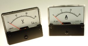
I have already done a couple of reviews of such a thing (see photo). Those devices ordered not for himself for friends. Comfortable device for homemade charging, and not only. I also envied and decided to order for myself. I ordered not only a voltammermeter, but also the cheapest voltmeter. I decided to assemble the power supply for my homemade. Which of them put on decisive only after the product collected completely. Surely there will be people who are interested.
I ordered on December 11. There was a small discount. Although so the price is low.
The parcel went for more than two months. The seller gave the left track from Wedo Express. But still the parcel reached and everything works. Formally no complaints.
Since it is this device that decided to imagine into my power supply, I will tell you a little more about it.
The devil came in a standard polyethylene package, "Propupus" from the inside. 
At the moment, the goods are not available. But it is not critical. Ali now many offers from sellers with a good rating. Moreover, the price is steadily reduced.
The device was additionally smelted to the anti-static package. 
Inside the actual device and wires with connectors. 
Key connectors. On the contrary, do not insert. 
Sizes are just miniature. 
We look at what is written on the seller page. 
My translation with adjustments:
-Pasy voltage: 0-100V
- Nonfit power scheme: 4.5-30V
-Mimal resolution (B): 0,01B
- consumption: 15th
-Please current: 0.03-10a
-Mimic resolution (s): 0,01A
All the same, but very brief, on the side of the product. 
Immediately disassembled and noticed that there are not enough minor details. 
But in previous modules, this place was occupied by a condenser. 
But the price has differed in the biggest.
All modules are similar as twin brothers. There is also a connection experience. Small connector is designed to pick up the scheme. By the way, at a voltage below 4V, the blue indicator becomes almost invisible. Therefore, we follow the technical specifications of the device, less than 4.5V do not apply. If you want to measure the voltage below 4V using this device, you need to power the scheme from a separate source through the "thin wire connector".
Current consumption of the device 15mA (when nutrition from 9V "Crown").
Three thick connector - measuring. 
There are two reading accuracy regulators (IR and VR). In the photo, everything is clear. Resistors are sturdy. Therefore, I often do not recommend twist (break). Red wires are conclusions for voltage, blue for current, black - "common" (interconnected). The colors of the wires correspond to the color of the indicator glow, do not confuse.
Head chip without name. It was once, but it was destroyed. 
And now I will check the accuracy of the readings using the sample installation of P320. Same to enter the calibrated voltages 2B, 5B, 10V, 12V 20V, 30V. Initially, the device undertook for one tenth volt on some limits. The error is insignificant. But I adjusted for myself. 
It can be seen that it shows almost perfect. Adjusted to the right resistor (VR). When rotating a ravenment clockwise adds, during rotation against - reduces the readings.
Now I'll see how the current is measured. Sweese the scheme from 9V (separately) and serve an exemplary current from the installation P321 
The minimum threshold from which the current of the current of 30mA begins to measure correctly.
As you can see, the current measures quite accurately, so I will not twist the fitting resistor. The device is measured correctly and at currents more than 10a, but at the same time the shunt begins to heat up. Most likely, the current limit is for this reason. 
With current 10a, I also do not recommend driving for a long time.
More detailed calibration results in the table. 
I liked the devil. But there are deficiencies.
1. Valpi V and A are painted, so they will not be visible in the dark.
2. Reclose measures the current only in one direction.
I would like to pay attention to the fact that the same devices would seem to be, but from different sellers, they can be different from each other. Be careful.
On its pages, sellers often publish incorrect connection schemes. In this case there are no complaints. That's just a little bit (scheme) changed to a more understandable eye. 
With this device, in my opinion, everything is clear. Now I will tell about the second device, about the voltmeter.
Ordered on the same day, but another seller:
Bought for US $ 1.19. Even at today's course - funny money. Since in the end I did not put this device, I will briefly go through it. With the same dimensions, the numbers are much larger, which is natural. 
This device has no trimmed element. Therefore, it can be used only in the form in which sent. Let's hope for Chinese conscientiousness. But I will check.
Installation is the same P320. 
In more detail in the form of a table. 
This voltmeter, though it turned out to be several times cheaper than Volammermeter, but his functionality did not suit me. It does not measure the current. And the supply voltage is combined with measuring chains. Therefore, below 2.6V does not measure.
Both devices have absolutely identical dimensions. Therefore, replace one to others in your homemade - the case is a minute. 
I decided to assemble the power supply on a more versatile voltammermeter. Devices inexpensive. Loads on the budget are not carried. The voltmeter is still in stock. The main thing is that the device has been good, and the application always exists. Just from the store and pulled the missing components for the power supply.
I have been lying for several years now this is a set of self-relocine. 
Scheme is simple, but reliable. 
The completeness of checking pointlessly, a lot of time has passed, claims to present late. But everything seems to be in place. 
Strip resistor (complete) is too narrow. I do not see his meaning. The rest will come true.
All shortcomings of linear stabilizers I know. Something more worthy I have neither time nor desire or opportunity. If you need a more powerful power supply with high efficiency, then I'll think about it. In the meantime, there will be what Made.
At first I fed the stabilizer fee.
At work found a suitable case.
Rewound the secondary of the torker trance for 25V. 
Pick up a powerful radiator for the transistor. All this shoved into the case.
But one of the most important elements of the scheme is a variable resistor. I took a multi-turn type SP5-39B. The highest output voltage accuracy. 
That's what happened. 
A bit non-zeal, but the main task is made. All electrical parts I defended myself, myself also defended from electrical parts :)
It remains a little "to raise". I will paint the case from the canister and make the front panel more attractive.
That's all. Good luck!
Connect an ammeter through the shunt. Selection and calculation of the device. Ammeter inclusion scheme
How to connect an ammeter to remove the readings
Electric chains have become an integral attribute of modern life. They permeate almost everything, and people do not even think that it is worth disappearing with electric current, and our world will be susceptible to serious danger. What is current, can it be measured and what will these testimony give for an ordinary person?
The laws of current behavior are studying at school, and, in principle, each high school student knows about the directional movement of charged particles. This movement of electrons inside the conductor and got the name of electricity. But any movement in nature - let the movement of water in the river, the movement of air masses or charges, can make a certain useful operation. And this is already interesting from a practical point of view. Knowing power, duration of exposure, the direction of the application of any strength, you can use it in solving certain vital issues.
Therefore, scientists are so busy with studying the surrounding and the creation of devices that allow all measurement and calculate. To obtain reports about the current, the device ammeter was invented. It allows you to determine the number of charged particles, which per unit of time pass through the known conductor cross-section, that is, current current.
What is an ammeter, its types
Ampmeter can be measured in any electrical circuit. This device is easy to know, it is denoted by the Latin letter A. Since the current is different, ranging from milliamps and above, there are different instruments or universal in power, in which the measurement limit changes. Moreover, various types of ammeters are needed for continuous and alternating current.
On the principle of device, devices are:
- Electromagnetic performance.
- Magnetoelectric.
- Thermal.
- Detector type.
- Induction.
- Electrodynamic system.
- Photoelectric.
- Thermoelectric.
The magnetoelectric device can determine the current strength in the circuits connected to constant voltage. Detection and induction type - measure variable currents. All other species can be universal.
The ammeters of electrodynamic and magnetoelectric execution are high sensitivity and accuracy.
How to connect an ammeter to an electrical circuit

Ampmeter of any type includes a sequential load in the electrical circuit. Then the same current passes through it as through the scheme. In order not to influence the current, does not obstruct it, the device is made with low input resistance. It is necessary to remember that connecting the ammeter in parallel with the load (incorrect connection), the entire current will go through it according to the principle of least resistance. Forgetting how to connect an ammeter, you can simply burn the device!
Before selecting the device, you must find out the current type - variable or permanent. After that, taking an appropriate ammeter (in the scale marking usually indicate a wave sign for AC voltage and straight line for permanent) to set the maximum measurement limit on it and only then think about how to connect an ammeter to the chain. After that, you need to remove the instrument readings. If they are significantly less than the exposed measurement limit, for example, the arrow is in the first half of the scale counting from zero, then it is necessary to rearrange the limit to one down. The readings are more accurate when the arrow is located in the second half of the scale.
DC values \u200b\u200bmeasurement
Permanent currents are present in many electronic circuits, it usually concerns power supplies, various charger. To fix such devices, masters you just need to know how to connect an ammeter. In practice, an ordinary person who is not associated with electronics can also also apply these knowledge, for example, to determine how much the battery is holding the battery from the camera.
Take a fully charged battery. Suppose its nominal voltage of 3.5 volts (B). They pick up the light bulb on such a nominal and collect the scheme: the battery is the measuring device - the light bulb. Record that shows an ammeter. For example, a light bulb consumes a current of 150 milliamme aperture (MA), and a capacity of 1500 milliammeleres (Mah) is written on the battery (Mah), which means a good battery must issue a current of 150 mA about 10 hours!

Measurement of AC values
Any household electrical device is a load that consumes alternating current. But, considering the issues of domestic use of electricity, power remains an important concept, because they pay precisely for kilowatts (kW). What is an ammeter in this case? Device of indirect measurement. With the help of it recognize the current and applying the formula:
P \u003d IU (OMA), where I is the current (a), U - voltage (B),
calculate power (P) (W).
For example, on the instrument is lost information about its parameters, in this case it is not without measurements. Or it is necessary to calculate the power of electricity consumption of any building, where to take into account all the instruments is simply impossible. Then the powerful ammeter is connected at the inlet of the power panel and measure. But in the latter case, you need tolerance that is only professional electricians!

Contact current measurement current
Sometimes to break the electrical circuit to turn on the measuring device is technically impossible, and the current must be measured (by conventional and high-voltage electrical circuits). How to connect an ammeter in this case? For this, the device of contactless measurement of current - current mites was developed. The principle of its action is based on the fact that any current passing through the conductor creates some electromagnetic field. The magnitude of this field is the greater, the greater the current power. Measuring the field strength indicator and transforming this data, the real value of the force expressed in amperes is obtained.
This is a very convenient way to perform measurements, because you do not need to think long, how to connect an ammeter. You can connect ticks directly to the charger and any electrical circuit on the insulated wire and read the testimony.

What needs to control the charge current in the battery
It seems that it is simpler: connected the car battery to the charger, waited the clock ten and the case is done - it is charged. In fact, it is very important to control the charge current, the recharge is also harmful as not a fully charged battery. This can lead to a reduction in its life. Therefore, it is desirable to think about how to connect an ammeter to the charger.
When the chain is collected and enabled, the ammeter shows the value of the charge current. If the battery is working, but discharged, it will gradually take the charge. That is, the charge current will begin to slowly reduce (within a few hours) until it stops at a certain value. When it happened, it is desirable to turn off the battery from the charger. If there is a sharp decrease in the current from the initial value (for half an hour), it means that the battery may be faulty.
In very good chargers there is a charging current adjustment function. Then at the beginning of the process, the charge current should be set up ten times less than the nominal battery capacity, which is indicated in its technical parameters.
fB.ru.
Connecting ammeters in a DC and AC network
With measurement of current force, we face very often. In order to learn the power of the device, the cable cross section for its power, the heating of the wires and other elements is it all depends on the current force. In order to directly measure this force, the device was invented by an ammeter. The ammeter is connected to the measured circuit only sequentially. Why? We will analyze just below.
As is known, the current is the ratio of the number of charges Δq, which passed through some surface during Δt. In the SI system, it is measured in amperes A (1 A \u003d 1 CL / s). In order to measure the number of past charges, the ammeter needs to be included in the circuit sequentially.
To minimize the effect of the immersion resistance of the ammeter and, accordingly, reduce the power of losses when measuring it is made as small as possible. If the ammeter with such internal resistance is connected in parallel, then a short circuit will occur in the chain. An example of the inclusion scheme:
The direct current is measured by direct estimates in the range of 10-3 - 102 A, electronic analog, digital, magneto-electric, electromagnetic, electrodynamic instruments - milliammeters and ammeters. If the current is over 100 and apply the shunt:
Shunts are typically made on different currents. The shunt is a copper plate having a certain resistance. When current flows through the plate, on it, according to the law, the OM U \u003d I * R drops some voltage, that is, there is a voltage between points 1 and 2, which will affect the coil of the device.
The resistance of the shunt, as a rule, is selected from the ratios:
Where RI is the resistance of the measuring winding of the device, the coefficient of the shunt, I is measured, and I are the maximum allowable current of the measuring mechanism.
If an alternating current is measured, it is important to know which value is measured (amplitude, mean, acting). This is important because all scales are usually in values \u200b\u200bvalid.
Variable values \u200b\u200babove 100 μA are usually measured by rectifying microammers, and below 100 μA - digital microammeters. For measurements in the range from 10 mA to 100 A, rectaging, electrodynamic, electromagnetic devices, which operate in the frequency range up to several tens of kilohertz, as well as thermoelectric, frequency range of which - to hundreds of megahertz.
To measure variables from 100 A and above, devices are used, but using current transformers:
The current transformer is a device in which the primary winding is connected to the current source (or as seen from the figure below, the primary winding "dresses" to the bus or cable), and the secondary to the measuring winding of any measuring device (the torque of the measuring device or the sensor should Have a small resistance).
To measure various kinds of currents, various methods and means are used. To correctly measure the required value and do not apply any harm, you need to correctly apply each measurement method.
elenergi.ru.
Do not know how to connect an analog ammeter
If you have an ordinary analog ammeter and you do not know how to connect it, then it is very simple. In addition to the ammeter, you need a shunt, as an ammeter measures the voltage drop on the shunt. The diagram of the connection of the ammeter with the shunt looks like this (drawing below). If there is no shunt, then it can be done myself and about it further in the article.If there is an ammeter and no shunt to it, it can be done independently. You can take a segment of the copper wire as a shunt, the thickness of this wire depends on the current force that will be measured. For example, for currents up to 10a, you can take a wire with a cross section of 1.5 kV, if the current is up to 30, then it is better to take a 2,5 kV wire.
You need a segment of about 30 cm, it must be cleaned completely from isolation. Next, connect this wire instead of shunt, I think everything is clear in the picture below.
Such a shunt is no worse than the factory, except of course appearance. And the ammeter calibrate is simple enough. We need a second ammeter that is connected sequentially with our shunt. You can up to our homemade shunt, and can after. We connect to the power source of the consumer of energy and look at how much the second ammeter shows. Next, we look at our ammeter and on a homemade shunt move the contacts of the ammeter, approach or remove them from each other so that the readings on both ammeters were the same. That's all when the readings of ammeters will be the same then it remains only to solder contacts from the ammeter to the shunt so that they do not move and the ammeter did not move.
After that, the ammeter is ready to work, and the self-made shunt can be put in some body or hide from the eye if you do not like it. In addition, the shunt can be made not only from the copper wire. A metal plate is suitable, even a simple bolt where the nuts can be clamping the wires from the ammeter and adjust the distance between the wires to calibrate the instrument.
Below in the photo is my ammeter with a homemade shunt.
I did not measure the length of the active zone of the Shunt, I can't say that I can't say on what distance the wires from the ammeter. Well, the cross section of the copper wire can be different and the ammeter itself, too, according to, this calibrate will still have. I did it with a multimeter. A few more photos of an ammeter with homemade shunt.
So it looks like everything from the reverse side, it can be seen as the wires from the ammeter and how to connect with this copper shunt
I think it is clear how the ammeter works and how to connect the shunt. The shunt connects sequentially, it is in the gap of one of the wires going to the energy consumer. You can like the plus to put the shunt and in minus. If the ammeter arrow deflects not to the other side, then you just need to turn the shunt. And so the ammeter measures the drop in the voltage on the shunt, the voltage drop is there in Millylololt.
Factory shunts in my opinion almost everything with a voltage drop to 75 mV, and the shunt must be selected according to the characteristics of the ammeter. If the ammeter on 50a and 75mv then it is necessary to buy the same, otherwise the ammeter will show it incorrectly. "I hope this information helped you, thanks for reading and leave comments.
e-veterok.ru.
| Some schemes and devices, such as power amplifiers, car chargers, laboratory power supplies, can have currents that reach up to 20 amps and more. It is clear that a couple of amps can be easily measured by an ordinary cheap multimeter, and what about 10, 15, 20 and more amp? After all, even on not very large loads, shunt resistors are built into ammeters for a long measurement time, sometimes even hours, they can overheat and in the worst case will float.
Professional tools for measuring high currents, quite expensive, so it makes sense to assemble the ammeter scheme itself, the more so there is no difficult thing here. Electrical scheme of a powerful ammeter
The scheme, as you can see, very simple. Its work has already been tested by many manufacturers, and most industrial ammeters work in the same way. For example, this scheme also uses this principle. Drawing of a powerful ammeter board
The peculiarity is that in this case the shunt (R1) is used with the resistance of a very low value - 0.01 Ohm 1% 20w - it makes it possible to dispel very little heat. The work of the ammeter schemeThe operation of the scheme is quite simple, when a certain current passes through R1 there will be a voltage drop on it, it can be measured, for this, the voltage is amplified by the OP1 operating amplifier and further enters the output through contact 6 to the external voltmeter included on the limit 2V.
The settings will be conclusted in the set of zero at the output of the ammeter in the absence of current, and in the calibration, comparing it with another, an exemplary tool for measuring the current. It feeds on an ammeter with a stable symmetric voltage. For example, from 2 batteries of 9 volts. To measure the current, connect the sensor to the line and the multimeter in the 2V band - see readings. 2 Volta will correspond to 20 amps current.
With the help of a multimeter and load, such as a small light bulb or resistance, we will measure the load current. Connect an ammeter and get current readings using a multimeter. We recommend performing multiple tests with different loads to compare readings with a reference ammeter and make sure that everything works correctly. You can download the printed Latin file here. |


el-shema.ru.

What is shunt? This word is borrowed from the English language ("Shunt", and literally means "branch"). It is physically comparable, since through this element connected in parallel to the measuring instrument, most of the current passes, and the smaller - the device itself is branched. This is its principle of operation similar to the bypass installed in heating systems.
To realize the need to turn on the ammeter through the shunt, remind briefly its device.
Inside the field of permanent magnet is the coil - frame. In its turns flows the measured current. Depending on the value of the measured parameter, the position of the coil relative to the constant magnetic field changes. The arrow of the device is rigidly fixed on its axis. The larger the measured current, the greater the arrow deflects.

In order for the frame to be turned to turn, its axis is fixed in the spyers, or hang out stretch marks. When using the scope of the frame, the frame runs along the spiral springs, if the movable part of the device is suspended on stretch marks, then they are current conductors.
It follows from this design that the value of the current in the frame is constructively limited. Springs and stretch marks cannot simultaneously be enough elastic and have a large cross section.
Connecting an ammeter through a current transformer
Expansion of the measurement limits of the ammeter is possible if an additional device called a current transformer is used. It works according to the principle of an ordinary transformer, but the primary winding contains only a few turns. When the measured current is passed, its value in the secondary winding will be less than several times.
But such transformers have appropriate dimensions and apply only in industrial networks. In the small-sized devices, their use is inappropriate.
Connect an ammeter through the shunt
If the device turns into a measuring chain directly, without a current transformer, it is called a direct inclusion ammeter.
Without shunt, you can use devices designed for a small current, order of milliamper. By shunting the measuring winding with resistance, greater than its own, we can change the measurement limit. The inclusion scheme is not different: the measured current passes through the shunt, and the ammeter is connected to it in parallel.
The first law of Kirchoff is entering the case. The measured current is divided into two: one proceeds through the frame, the second - through the shunt.

They will relate to each other like this:

Calculation of the resistance of Shunta
It follows from this that, knowing the total deflection of the measuring system (IPR) and the internal resistance of the frame (RPD), you can calculate the required resistance of the shunt (RS). And thereby change the measurement limit of the ammeter.
But, before you remake the milliammeter in the ammeter, you need to solve two difficult tasks: to know the total rejection of the measuring system and its resistance. You can find this data, knowing the type of milliammeter that is redone. If it is impossible, you will have to hold a number of measurements. Resistance can be measured by a multimeter. But for the second parameter, it will be necessary to apply on the device current from a foreign source, measuring its value using a digital ammeter.
 But this calculation of the shunt for ammeter will not be accurate. It is impossible to provide the desired measurement accuracy with the helm. The schunts measurement system has a greater sensitivity to error when determining the source data. Therefore, in practice, an accurate fit of the shunt resistance and an ammeter calibration is carried out.
Fitting the measuring system
For the manufacture of factory products, materials are used that do not change their characteristics in a wide range of temperatures. Therefore, the best option is the selection of the finished shunt and fit for its purposes to decrease the section and the length of its conductor to the calculation of the calculated value. But for the manufacture of a shunt for an ammeter, you can use both infirred materials: copper or steel wire, even clips fit.
Now the power supply is required with the voltage regulator to give the required current. For load, you can use the resistor of the appropriate power or incandescent lamp.
First we achieve the correspondence of the complete deviation of the device arrow at the maximum value of the measured value. At this stage, we select the resistance of our homemade to the highest possible coincidence with the final risk on the scale.
Then check whether intermediate risks coincide with the values \u200b\u200bcorresponding to them. If not, we disassemble the ammeter and redraw the scale.
And when everything turned out - we set the finished device in your place.
electriktop.ru.

Very often in our life, the situation arises, in which we need to measure the current strength. For what? To find out the estimated power of a particular equipment, for example. To determine the potentially level of cable heating and so on. Approximately for these purposes, we will need an AC ammeter. It is he who serves to measure the strength of the current. By the way, using the device can be measured by the force of not only alternating, but also direct current. How to use this tool?
Connection
To understand how to connect an ammeter, you need to understand the principle of the measurement range. That is, the device works in a certain range, measuring from values \u200b\u200bin the MCA to values \u200b\u200bin ka. Given the technical scheme of the connection, you should get the maximum level of the scale current. The connection itself occurs sequentially, and not in parallel existing load. Otherwise, there is a risk of overstrain of the device. Accordingly, it will become non-functional, simply speaking, will be overgrown.
An important point is that the measured current is highly dependent on the overall chain resistance. It follows from this that the internal resistance of the device must be extremely small. Otherwise, the accuracy class of the results may be questionable. After all, the equipment itself will affect the numerical indicator. To figure out more accurately, you will need an ammeter connection scheme.

Shunt
How to connect an ammeter if the current value that is necessary for the measurement exceeds the possibility of the device? For this, a variety of shunts are used. They allow you to expand the measurable current range. The load will be distributed in favor of the shunt, it will take on a large part. In fact, the shunt simply will show a decrease in the current that fixes the device. In this case, it will work on the principle of the Millivoltmeter, however, its indicators will be in amperes, and therefore the ultimate information will be correct. For a more detailed understanding, a scheme is needed to include an ammeter through the shunt.

Where is the ammeter applied?
DC ampermeter is used everywhere. If we exclude household needs, then the first option will be large industrial enterprises. Naturally, only those that, one way or another are engaged in the creation (generation) and further consumption of electric or thermal energy. In addition, the device has found wide use in construction. No serious project passes without this little assistant.
A variety of equipment
The device of the ammeter can be quite different depending on the model. If you classify them by the type of reference, you can select the arrow, light and electronic variants. The permanent current ampere can be different as well as methods of its operation. There are a series of wider, and stay on it is worth more.
 Electromagnetic ammeters are needed to measure alternating current with low frequency. The ammeter scheme of this type is the simplest, respectively - they are the most cheap on the market. If you wonder how the device is called a high frequency current measurement, then this is a thermoelectric meter. The principle of the ammeter of this kind is the work of the conductor and thermocouples. The conductor using the current currently heats the thermocouple, which serves as the method of calculating the current force.
Ferrodynamic devices are needed for a stressful medium with an increased magnetic field. They are more resistant to external and internal influences. The very last word of technology is a digital ammeter. These are the most progressive models that are not afraid of strong voltage, mechanical damage. They are much easier to master and use. How to connect a digital ammeter? In most cases, if the manufacturer does not specify another, just like the usual one.
At this, the main types of ammeters can be considered exhausted. Some users, however, consider that we missed one species. Namely a voltmeter.
The differences of the voltmeter from the ammeter
To begin with, let's just analyze the etymology of words. It is immediately clear that the devices occurred from the words "Ampere" and "Volt". And although the first can connect to the same chain as a voltmeter, they have completely different destination. Amp - a unit of measurement of current strength, while Volt is a unit of voltage measurement unit. So what is the ammeter different from the voltmeter? That's right, the first measures the strength, and the second voltage.
electriktop.ru.

In the manufacture of homemade power supplies or chargers, folk craftsmen often equip such devices with digital voltammeters. The price of such devices ranges in the area of \u200b\u200bseveral dollars, and their accuracy allows you to easily forget about the arrow measurement instruments. Given the wide range of modern voltammeters, you can encounter the problem of their connection. Today, our article is devoted to the most popular voltammermeters and their connection schemes. Also, in addition to the standard scheme, we will describe how to connect a voltammermeter to the charger
How to connect a voltammermeter to the charger - a selection of schemes
We have chosen the 4 most common voltammeters that use craftsmen in their devices. The measurement ranges of most instruments are 0-100 V, and also have a built-in shunt on 10 A. The principle of connection is very similar, but there are their nuances.
TK1382 voltammermeter can be bought at 3.5-5 cu. The device has two calibration resistors: voltage adjustment, adjustment of the current.

Measured voltage 0-100 V; Current 0-10 A. Food the device must be within 4.5-30 V.


YB27VA Connection diagram
Voltmeter Ampmeter YB27VA has similar parameters for the range of current measurement and voltage. The only difference becomes another board layout and wiring color marking.

The approximate price is 3.5-4.5 cu, there are also rapid resistors on the board.


DSN-VC288 Connection Scheme
Voltmeter Ampmeret DSN-VC288 is also one of the most popular in radio amateurs. Its price varies within 4 cu

Many who have come across such devices complain about the poor quality of calibration resistors.


BY42A Connection diagram
Who needs high measurement accuracy, can use the BY42A voltammermeter. Such an appliance will give one after a comma larger.

Voltmeter Ampmeter By42A is designed for a higher measured voltage - up to 200 V, but the supply voltage of the device must be within 3.8-30 V.

Also, BY42A can be found in two options for execution of the board, but the color marking of the wires remains the same.

Using a voltammermeter in its car charger, you can not only visually control the process of charging the battery, but also timely diagnose the battery status. It will be enough to connect the charger where the voltammermeter is installed to the battery, and we will see what a voltage on it now.
In contact with
Odnoklassniki.
Comments Powered by Hypercomments
diodnik.com.
Designation Diode Bridge in the Scheme

Corner Cabinet drawings and photo schemes
In ammeters current passing in the device, creates a torque that causes the deviation of its movable part to an angle depending on this current. At this corner of deviations determine the amount of the ammeter current.
In order for an ammeter to measure the current in some kind of energy receiver, the ammeter must be connected in series with the receiver so that the receiver and ammeter current is the same.
The resistance of the ammeter should be not enough compared to the resistance of the energy receiver, in order to be enabled, so that its inclusion is practically affected by the value of the receiver current (on the mode of operation of the chain).Thus, the resistance of the ammeter should be small and the smaller, the more its rated current. For example, at rated current 5 and the resistance of the ammeter is R A \u003d (0.008 - 0.4) Ohm. With a small resistance of the ammeter, small and power losses in it.
Fig. 1. Implementing an ammeter and voltmeter
At the rated current of the ammeter 5 and the power of the loss P a \u003d i 2 r \u003d (0.2 - 10). The voltage applied to the clamping voltmeter causes the current circuit. With a constant current depends only on voltage, i.e. IV \u003d F (UV).This current, passing but the voltmeter, as well as in the ammeter, causes the deviation of its movable part to an angle depending on the current. So in order, each voltage value at the voltmeter clamps boo fully defined current values \u200b\u200band angle of rotation of the movable part.
In order for the voltmeter to determine the voltage at the power receiver clips or the generator, it is necessary to connect it to the voltmeter clamps so that the voltage on the receiver (generator) is equal to the voltmeter voltage (Fig. 1).
The resistance of the voltmeter should be large compared to the resistance of the energy receiver (or generator) so that its inclusion does not affect the measured voltage (on the operation mode of the chain).
Example. To the clamps of the chain with two successively by connecting receivers (Fig. 2) having resistance
r1 \u003d 2000 Ohm and R2 \u003d 1000 Ohms applied voltageU \u003d 120 V. 
Fig. 2. Voltmeter inclusion scheme
At the same time on the first receiver voltage
U1 \u003d 80 V, and on the second U 2 \u003d 40 V.If parallel to the first receiver, turn on a voltmeter with resistance
rv \u003d. 2000 ohm for measuring the voltage on its clips, then the voltage both on the first and on the second receivers will be importantU "1 \u003d U" 2 \u003d 60 V.Thus, the inclusion of the voltmeter caused a voltage change on the first receiver with
U1 \u003d 80 V to U "1 \u003d 60In, that is, the error in the measurement of the voltage caused by the inclusion of the voltmeter is equal to ((60 V - 80 V) / 80 c) x 100% \u003d -25%Thus, the resistance of the voltmeter should be greater and the greater the greater the rated voltage. At rated voltage 100 in the resistance of the voltmeter
rV = (2000 - 50000) Ohm. Due to the large voltmeter resistance, the power of losses in it.At rated voltmeter voltage 100 in the power of losses
v \u003d (UV 2 / RV) VaFrom the above, it follows that the ammeter and the voltmeter may have measuring mechanisms of the same device, differing only in their parameters. But the ammeter and voltmeter are in different ways in the measured chain and have different internal (measuring) schemes.
With measurement of current force, we face very often. In order to learn the power of the device, the cable cross section for its power, the heating of the wires and other elements is it all depends on the current force. In order to directly measure this force, the device was invented by an ammeter. The ammeter is connected to the measured circuit only sequentially. Why? We will analyze just below.
As is known, the current is the ratio of the number of charges Δq, which passed through some surface during Δt. In the SI system, it is measured in amperes A (1 A \u003d 1 CL / s). In order to measure the number of past charges, the ammeter needs to be included in the circuit sequentially.
To minimize the effect of the immersion resistance of the ammeter and, accordingly, reduce the power of losses when measuring it is made as small as possible. If the ammeter with such internal resistance is connected in parallel, then a short circuit will occur in the chain. An example of the inclusion scheme:
The constant current is measured by the instruments in the range of 10 -3 - 10 2 A, electron analog, digital, magnetic electrical, electromagnetic, electrodynamic instruments - milliammeters and ammeters. If the current is over 100 and apply the shunt:

Shunts are typically made on different currents. The shunt is a copper plate having a certain resistance. When current flows through the plate, on it, according to the law, the OM U \u003d I * R drops some voltage, that is, there is a voltage between points 1 and 2, which will affect the coil of the device.

The resistance of the shunt, as a rule, is selected from the ratios:
Where R and is the resistance of the measuring winding of the device, the coefficient of the shunting, I is measured, and I - the maximum allowable current of the measuring mechanism.
If an alternating current is measured, it is important to know which value is measured (amplitude, mean, acting). This is important because all scales are usually in values \u200b\u200bvalid.
Variable values \u200b\u200babove 100 μA are usually measured by rectifying microammers, and below 100 μA - digital microammeters. For measurements in the range from 10 mA to 100 A, rectaging, electrodynamic, electromagnetic devices, which operate in the frequency range up to several tens of kilohertz, as well as thermoelectric, frequency range of which - to hundreds of megahertz.
To measure variables from 100 A and above, devices are used, but using current transformers:

The current transformer is a device in which the primary winding is connected to the current source (or as seen from the figure below, the primary winding "dresses" to the bus or cable), and the secondary to the measuring winding of any measuring device (the torque of the measuring device or the sensor should Have a small resistance).
Electrical chains are present in all spheres and branches of the modern person. It is worth stop the flow of current and its quality will deteriorate significantly, a lot of serious dangers will arise from different sides. To constantly regulate the maintenance of the power grid, you need to know how the ammeter is connected. This device is measured by the current of the current.
General information about the device
The laws of the electrical chain are taught in educational institutions. Each teenager is known for nuances about directed motion of charged particles. It is represented by moving electrons by conductor and is called electricity. If we consider the practical side, any movement of something in nature (air masses, charges, water in the river) can benefit humanity.

It is only necessary to determine the duration of the force, its direction, power.
Based on this, various devices are created, calculating and measuring all kinds of values. For example, to have a detailed view of the current, it is worth using an ammeter. The device easily determines the number of charged particles that intersect the section set in the conductor for a certain period (unit) of the time, which is the current power.
The concept and types of ammeter
The device is suitable for determining the current strength in any existing power grid. The subject is easily recognizable by the existing Latin literator "A". The impermeter connection scheme is extremely simple. You only need to decide on the value of the current starting milliamepers.

Also, the devices are divided into those calculated for certain power, and universal with a changing measurement limit. It is worth noting that various types of ammeters are used to work with variables and direct current. They are also different on the principle of the device:

The scheme for switching on the ammeter of the magnetoelectric type is extremely simple. It makes it possible to find out the strength of the current in the network driven by constant voltage. With variable indicators, it is more appropriate to work with induction, detector devices.
Other devices are usually universal in use. The feature of the aggregates in magnetoelectric and electrodynamic design is the maximum accuracy and high sensitivity.
Connect to chain
To understand how to connect an ammeter of any complexity, you need to know that it is turned on sequential load. In this case, the device will pass the current similar to electricity in the measured network.
 Devices are specially manufactured with minor input resistance. This is how severe influence on the current is prevented, it turns out to be a minimal obstacle. It should be remembered that with an incorrect connection, when the ammeter is connected parallel to the load, the current will be directed through the described unit, namely it will work the longest resistance rule. In such situations, in practice, current meters simply fail.
Before buying an ammeter, you need to know with what force it will work, - a constant or variable. Deciding on the label on the scale with the choice of the device, it is recommended to set maximum power., Think over the correct connection to the network.
Next, the indicators are removed from the meter. When they are smaller in comparison with the exhibited limit, and the arrow is located in the first part of the gradient, it should be moved to the other side of the scale with the designation of the most accurate values.

Definition of DC
A similar type of electricity passes through various electronic circuits. A bright example will be all sorts of chargers, power supplies. To repair such fixtures, the master should know and understand how the ammeter is connected to the chain.
 In domestic conditions, such knowledge will not be superfluous. They will help a person who does not enjoy the radio electronics, to independently determine, for example, the time for which the battery charging is enough from the camera.
For the experiment, you will need a fully charged battery with a nominal voltage, for example, at 3.5 volts. Also it is worth a light bulb of a similar nominal to create a sequential scheme:
- battery;
- ammeter;
- lamp.
The entry indicated on the measuring device is fixed. For example, the lighting product consumes electricity with a capacity of 150 milliamperes, and the battery has a capacity of 1500 milliamme aperture. It means the latter must function for 10 hours, giving out a current of 150 mA.

Measurement of variable electricity
Any household appliances that feed on the network show the load with which they consume a current of an alternating type. When considering energy use, it is worth remembering the concept of power for which the final payment is made in kilowatts. In this case, the ammeter performs the device to perform indirect measurements. In this way, the current is determined through the standard formula according to the Ohm law:
P \u003d I * U, where:

There are cases when information is lost, fixed by the electric tailor. To restore the required parameters and you will need an ammeter. Sometimes, when servicing a large-scale building, there is no possibility of controlling all devices that fix electricity. The problem is solved by connecting the reinforced ammeter to the output from the shield, removing the measurements of the measurements. Such tasks are allowed to perform only specially trained people.
Contactless measurement
It happens that the rupture of the electrical inspection without inclusion of the measuring unit is impossible for technical reasons. You need to find out the current values, it applies to working with high-voltage and ordinary networks. The voltmeter connection scheme, an ammeter in such cases involves the use of special current ticks, which allow you to contactlessly produce the measurements.
 The principle of operation of such a fixture is based on the fact that the current enters the conductor, thereby creating a certain magnetic field. The values \u200b\u200bof these values \u200b\u200bare interdependent. The tension in the existing field is measured, transformed according to the formula, and at the output it turns out a real rate expressed in amperes.
This method is often used in practice due to simplicity, convenience and safety, the absence of the need to apply an ammeter, thinking how to enter it into the chain. For example, ticks are fixed on an isolated wire of any chain and a charger, after which the necessary indicators are simply removed. Significant drawback is their high cost.
The ammeter is a popular device when working with power grids. At home, it brings no less benefit. The use of such an aggregate is extremely simple and simple.