Stop motion animation
A frame-by-frame animation consists entirely of keyframes, and you create the contents of the frames yourself. This is similar to the process of creating cartoons, when each frame is drawn on a separate sheet, and if you have 5000 frames in the cartoon, then you will have to draw 5000 drawings accordingly. In Flash this is, of course, much easier to do than on paper, but it's still hard work, besides, the file size with frame-by-frame animation turns out to be large. In flash, frame-by-frame animation is used when a problem cannot be solved in other ways. To make it clearer what is at stake, let's try to create a simple, frame-by-frame animation of shifty eyes.
In a new document, select a tool Oval Tool (O) disable the creation of fills in the palette fill color and draw an oval. With a tool Selection Tool (V) edit it as shown in the picture. Then select the picture, and holding the key alt Let's make a copy of the drawing.

Let's choose a tool Oval Tool (O) in the panel color mixer select a radial fill for the left slider set White color and blue for the right.

Draw one eye and then with the tool Selection Tool (V) select it, and holding the key alt copy.

Now we are all set to start making animation.
On panel Timeline for the first layer in the tenth frame, insert a keyframe.
Insert > Timeline > Keyframe, this is done so that we have it visible throughout all ten frames.

For the second layer in the third frame, insert a keyframe and use the tool Selection Tool (V) drag the pupils a little, then insert a keyframe in the fifth frame and move the pupils a little more, and so on until the tenth frame.

That's all, you can test the video, as you already know, this is done using a keyboard shortcut Ctrl+Enter.

Motion animation
Creating a motion animation differs from frame-by-frame animation in that we do not need to create each frame manually, it is enough to create the first animation frame and the last one, the program will fill in all the intermediate frames automatically. Keep in mind that tweening is only applicable to symbols and there should be no more than one animated symbol on one layer.
Before we start doing something in practice, let's define for ourselves what animation is? Animation is the changing properties of an object over time.
Now let's take an example of the process of creating a motion tween.
With a tool Text Tool (T) write some text and convert it to graphics, you can do this by applying the command twice Break Apart menu Modify or keyboard shortcut ( ctrl+b).

Select the twentieth frame on the panel Timeline and make it the key by choosing in context menu team Insert Keyframe. In any frame between the first and twentieth, call the context menu and select the command Create Motion Tween(Create motion animation). If everything is done correctly, the intermediate frames should turn bluish, and the first and twentieth frames should be connected by an arrow, which means that the program has generated intermediate frames between the first keyframe and the twentieth.

Now everything is ready, but we won’t see any animation yet because we have the same first and last frame, but we’ll fix it now.
Let's make the text invisible at first but gradually appear.
To do this, select the first key frame and in the panel Properties drop down list color select item Alpha(transparency), use the slider to set the value to 0.

Let's test the video ( Ctrl+Enter)
Thus, we can move an object, rotate, change color, size, and also apply filters, and all this can be done with several objects placed on different layers at once, can you imagine what scope for creativity?
Creating the movement of objects along a path
This lesson will teach you the simplest movement of an object along a path, this function appeared in the early versions of Flash, and is very often used today. To implement this feature, we need nothing at all: a layer with a trajectory, converted into a special type of layer - Layer Mask, and, accordingly, the object itself. For example, if you want to create a simple animation of a racing car moving along a track, then you will not need to use any complex ActionScipt functions, just remember this lesson.
Draw a trajectory
To do this, we just need to draw a line (not necessarily closed) on the very first layer, using, for example, “ pencil tool". I recommend that you set anti-aliasing to Smooth in the pencil options so that the movements are smooth and without jerks.


Creating a "path" layer
Now we need to convert this layer into a "trajectory" layer. Right-click on the layer on which our trajectory is located and select " guide". The icon in front of the layer name should change from leaf to hammer. If so, then you are doing everything right correctly and are already close to the final result. Now that the "path" layer is ready, we need to subordinate the layer with the object to it. To do this, we will create new layer, place a drawing on it that should move along the path, then hold left button mouse on a new layer and drag under the path layer so that the layer becomes dependent (the icon and name of the layer will move slightly to the right, the icon of the layer with the path will also change).


Creating object movement
However, this is not all. Now we need to make the object move along the path. To do this, on the layer with the object, move it to the beginning of the path:

Go to frame 15 and create there key frame pressing F6. In this frame, move the object to the end of the path:

Now, in order for the body to move, we need to create motion tween. To do this, right-click on the space between the first and last frame and select Create Motion Tween, check the box in the properties Orient to path. Everything, now for 15 frames the object will move from the beginning of the trajectory to its end.
IMPORTANT: When creating a closed trajectory, do not forget that the flash chooses the shortest path, and if you simply move the object on the last frame lower along the trajectory relative to the first frame of movement in a circle, you can see for yourself. To do this, you can divide the trajectory into three sections, i.e. the starting point for the second section will be the end of the first, for the third - the end of the second, and so on. Good luck!
Orientation along the path
Of course, the car is moving incorrectly. It is necessary to associate its movement with a layer of guides. This time we will not create a new layer, but use a layer Path, which just contains the path outline.
Now the car is moving along the desired trajectory, but incorrectly - it moves either sideways or backwards. Of course, it was possible to put a few more keyframes between the end points in which to turn the car correctly. However, you can make the car take the desired direction along the entire trajectory with one click.
Finally, let's make the car stand outside the house for a while before the next cycle of the video starts.
The technology for creating movement along the trajectory is as follows:
- Create a new file ( Ctrl-N).
In the work area:
- Draw a circle in the upper left corner of the stage and fill it with a radial gradient (a keyframe will appear in the first frame).
On the timeline:
- Create a simple calculated animation for 30 frames:
- The first frame should be selected, if not, select it. From the main menu select Insert - Timeline - Create Motion Tween(or in the context menu). The frame is now light purple.
- Create a keyframe at the 30th frame.

When you click on the buttons in the timeline
-Onion Skin Outlines(Contiguous frames as outlines) - displays the outlines of adjacent frames,
- Edit Multiple Frames(Editing multiple frames) - mode of simultaneous editing of several frames - the specified object states are visible - the ball and contours - all the calculated states provided by the use of twinning (black arrow on a light purple background)
- In order to add a guide layer, you need to select the layer on which your symbol (ball) is located, and by pressing the right mouse button, select Add Motion Guide(Add guide layer). In this case, the original layer with the ball becomes guided ( guided layer). You can also add a guide layer using the button below the layers (see the topic about layers).
- Now in layer guide you need to draw a trajectory of movement. The path can be any curve that is not a fill area.
- Select the first frame in this layer and draw any curve in the workspace. The control layer is ready. You can disable it for editing to make it more convenient to work, and in the future, make it completely invisible.
- In order for the animation along the path to work, you need to bind the symbol to the path. To do this, you need to take (with the left mouse button) the symbol by the central point and drag it onto the path.
- As soon as you see a small circle on the symbol, it will mean that it is "hooked" on the trajectory. You will feel when the symbol "hooks" on it, and see how it will slide on it. The same must be done for the second keyframe in frame 30 - attach the symbol to the end of the path. If you want the object to rotate according to the path, and not just move along it, then on the panel Properties checkbox must be enabled Orient to path.

- And to check the binding of the symbol to the path, press the buttons -Onion Skin Outlines(Contiguous frames as outlines) and - Edit Multiple Frames(Editing multiple frames). If you see symbol outlines along the path, then the binding was successful. If not, try again from point 8 of this example.
- Test your animation.

If you want the object to rotate according to the path, and not just move along it, then on the panel Properties checkbox must be enabled Orient to path.
5.1 General instructions
5.1.1 Programming the parameters of motion along the path
IN This chapter describes commands that can be used to optimize motion parameters at frame boundaries to meet special requirements. Thus, for example, it is possible to carry out sufficiently fast positioning of the axes or, accordingly, to reduce the contours of the trajectory after several blocks, taking into account the acceleration limit and the overload factor. As the speed increases, the inaccuracies of the trajectory contour also increase.
The trajectory commands are programmed with the corresponding parameters.
Principal description
When changing the direction of travel in path control mode, the contour transitions are smoothed out and the programmed positions are not approached exactly. This makes it possible to walk around corners continuously at as constant a speed as possible, or to optimize transitions with additional commands. With the exact stop function using additional criteria, machining accuracy can be realized with max. accuracy. The control automatically calculates the speed control a few blocks ahead using Look Ahead.
For axes, acceleration processes can be activated both in a mechanically friendly and in a time-optimized mode. These include path axes as well as positioning, geometry and following axes, which, depending on the program run, can also be switched from the respective blocks of the current machining. The type of precontrol and which axes should use precontrol can also be defined. When machining without pre-control, max. permissible contour error.
Between two NC machining blocks, a dwell time or a block with an implicit preprocessing stop can be inserted.
For each typical toolpath command, a programming example is provided.
5.1 General instructions
Functions for optimizing motion parameters at frame boundaries
Optimization of motion parameters at frame boundaries is possible using the following functions:
activating modal or block-by-block exact stop
exact stop definition with additional exact stop windows
constant speed trajectory control mode
path control mode indicating the type of grinding
trajectory control mode with forward speed control
activation of the parameters of acceleration and speed of the axes
percentage control of the acceleration of the driven axes
smoothing the speed of movement along the trajectory
motion with pre-control to increase the accuracy of the trajectory
enable programmable contour accuracy
activation of programmable waiting time
(without waiting time) |
|
rapid traverse
Programming Manual, Edition 10.2004, 6FC5 298-7AB00-0PP1 |

Path parameters
5.2 Exact stop (G60, G9, G601, G602, G603)
Precise stop functions are used when it is necessary to create sharp outer corners or to finish inner corners to size.
The exact stop criteria "Exact stop window fine" and "Exact stop window coarse" determine how exactly the corner point is approached and when the switch to the next block is made. At the end of the interpolation, you can start a block change at the end of the block if the control has calculated a setpoint velocity of zero for the axes involved.
Programming
Options
Fine and coarse limits for exact stop can be set for each axis via machine data. The speed is reduced to zero until the exact destination position is reached at the end of the block.
indication
G601, G602 and G603 are only effective when G60 or G9 is active.

Path parameters |
|||
5.2 Exact stop (G60, G9, G601, G602, G603) |
|||
;G60 still active |
|||
;exact stop window fine |
|||
;switch to trajectory control mode |
|||
;exact stop only effective in this block |
|||
;back to trajectory control mode |
|||
Description
Exact stop, G60, G9
G9 creates exact stop in the current block, G60 in the current block and in all subsequent blocks.
The G64 or G641 path control mode functions disable G60. G601/G602
The movement slows down and briefly stops at the corner point.
Note Set the exact stop limits as close to each other as necessary. How
the closer the boundaries are fixed to each other, the longer the position compensation and the transition to the destination position take.
End of interpolation, G603
A block change is triggered when the control calculates the speed setpoint for the involved axes to be zero. At this point in time, the actual value - depending on the dynamics and speed of the path - lags behind by a coast down distance. This makes it possible to grind the corners of the workpiece.
Programming Manual, Edition 10.2004, 6FC5 298-7AB00-0PP1 |

Path parameters
5.2 Exact stop (G60, G9, G601, G602, G603)
Command output In all three cases:
The auxiliary functions programmed in the NC block are activated after the end of the movement.
Note Machine manufacturer
It can be fixed in the channel-specific machine data so that preset criteria other than the programmed exact stop criteria are used automatically. If necessary, they take precedence over programmed criteria. Criteria for G0 and other G commands of the 1st G code group can be stored separately, see function descriptions, FB1, B1.
Programming Manual, Edition 10.2004, 6FC5 298-7AB00-0PP1 |

Path parameters
5.3 Continuous path control mode (G64, G641, G642, G643, G644)
In path control mode, the contour is machined at a constant path speed. The uniform speed results in better cutting conditions, better surface quality and shorter machining times.
Caution In the path control mode, there is no precise approach to
programmed contour transitions. Sharp corners are created with G60 or G9. The path control mode is interrupted by text outputs with "MSG" and blocks that cause an implicit preprocessing stop (eg access to certain machine status data ($A...)). The same applies to the output of auxiliary functions.
Programming
G641 ADISPOS=…
G642 ADISPOS=…
Programming Manual, Edition 10.2004, 6FC5 298-7AB00-0PP1 |

Path parameters
5.3 Continuous path control mode (G64, G641, G642, G643, G644)
G643 ADISPOS=…
Options
indication
Resurfacing is not a substitute for corner rounding (RND). The user should not assume what the contour will look like inside the resurfacing zone. The type of grinding may also depend on dynamic properties, for example, the speed of movement along the path. Therefore, resurfacing on the contour only makes sense with small ADIS values. If under all circumstances it is necessary to pass a certain contour at the corners, then RND should be used.
ADISPOS is used between G0 frames. Thus, when positioning, the axial stroke can be significantly smoothed and the travel time reduced.
If ADIS/ADISPOS is not programmed, the value zero and the motion characteristic as for G64 apply. With short travel distances, the regrinding interval is reduced automatically (up to max. 36%).
With this part, the approach is carried out exactly to the groove at two corners, otherwise the work is carried out in the path control mode.
Programming Manual, Edition 10.2004, 6FC5 298-7AB00-0PP1 |
![]()
Path parameters
5.3 Continuous path control mode (G64, G641, G642, G643, G644)
exact stop fine
N10 G17 T1 G41 G0 X10 Y10 Z2 S300 M3 |
;go to starting position, |
;turning on the spindle, path correction |
|
N20 G1 Z-7 F8000 |
;tool feed |
N30 G641 ADIS=0.5 |
;grinding contour transitions |
N50 X60 Y70 G60 G601 |
;exact approach to position with exact stop fine |
N90 G641 ADIS=0.5 X100 Y40 |
;grinding contour transitions |
N120 G40 G0 X-20 |
;turn off path correction |
;retract tool, end of program |
indication
For an example of rounding with G643, see also: Literature /PGA/ Programming Guide "Advanced Programming", Chapter 5, Adjustable Path Ratio, SPATH, UPATH
Trajectory control mode, G64
In path control mode, the tool traverses tangential contour transitions at a possible constant path speed (without deceleration at block boundaries). Corners (G09) and blocks with exact stop are braked ahead (Look Ahead, see following pages).
Programming Manual, Edition 10.2004, 6FC5 298-7AB00-0PP1 |

Path parameters
5.3 Continuous path control mode (G64, G641, G642, G643, G644)
The passage of corners is also carried out at a constant speed. To reduce loop errors, the speed is reduced accordingly, taking into account the acceleration limit and the overload factor.
References: /FB1/ Description of Functions, B1, Path Control Mode.
Note The overload factor can be set in machine data 32310.
grinding contour transitions depends on the feed rate and the overload factor. With G641, you can explicitly specify the required regrinding zone.
Resurfacing cannot and should not replace the functions for specific smoothing: RND, RNDM, ASPLINE, BSPLINE, CSPLINE.
Trajectory control mode with programmable transition grinding, G641
With G641, the control inserts transition elements at the contour transitions. With ADIS=… or ADISPOS=… you can specify to what extent the corners are ground. G641 acts like RNDM but is not limited to work plane axes.
Example: N10 G641 ADIS=0.5 G1 X… Y…
The rounding block can start at the earliest 0.5 mm before the programmed block end and must end 0.5 mm after the block end. This setting is modal. G641 also works with Look Ahead speed control. Grinding blocks with a strong bend are approached at a reduced speed.
Programming Manual, Edition 10.2004, 6FC5 298-7AB00-0PP1 |

Path parameters
5.3 Continuous path control mode (G64, G641, G642, G643, G644)
Continuous path mode G64/G641 on several blocks
To avoid undesired stopping of the path (free cutting), the following must be observed:
Auxiliary function output leads to a stop (exception: fast auxiliary functions and auxiliary functions during movements)
Intermediately programmed blocks with only comments, calculation blocks or subroutine calls do not cause any interference.
Resurfacing extensions
If not all path axes are included in FGROUP, a speed jump often occurs at block transitions for the axes not included, which the control limits by reducing the speed at the block change to the value permitted via MD 32300: MAX_AX_ACCEL and MD 32310: _MAX_ACCEL_OVL_FACTOR. This braking can be avoided by softening the given positional relationship of the path axes through resurfacing.
Sanding with G641
With G641 and specifying the ADIS (or ADISPOS in rapid traverse) rounding radius for path functions, rounding is switched on modally. Within this radius around the block change point, the control can break the path connection and replace it with a dynamically optimal path. Disadvantage: Only one ADIS value is available for all axes.
Regrinding with axial precision with G642
G642 modally activates rounding with axial tolerances. Regrinding is not carried out within the defined ADIS range, but rather the following defined by machine data MD 33100:
COMPRESS_POS_TOL axial tolerances. The rest of the principle of operation is identical.
Programming Manual, Edition 10.2004, 6FC5 298-7AB00-0PP1 |
Path parameters
5.3 Continuous path control mode (G64, G641, G642, G643, G644)
With G642, the rounding path is determined from the shortest rounding path of all axes. This value is taken into account when creating the resurfacing block.
Rounding inside a block with G643
The maximum deviations from the fine contour during rounding with G643 are set via machine data MD 33100: COMPRESS_POS_TOL[...] for each axis. G643 does not create its own rounding block, but inserts axis-specific rounding movements within the block. With G643, the grinding path for each axis can be different.
Rounding with contour tolerance for G642 and G643
WITH With the help of the enhancements described below, parameters G642 and G643 are improved and rounding with contour tolerance is introduced. When regrinding with G642 and G643, the permitted deviations of each axis are normally specified.
WITH With MD 20480: SMOOTHING_MODE rounding with G642 and G643 can be configured in such a way that a contour tolerance and an orientation tolerance can be specified instead of axis-specific tolerances. Here, the contour and orientation tolerances are set using two independent setting data that can be programmed in the NC program, allowing them to be set differently for each block transition.
Installation data
SD 42465: SMOOTH_CONTUR_TOL
This setting data is used to set the maximum grinding tolerance for the contour.
SD 42466: SMOOTH_ORI_TOL
With this setting data, the maximum grinding tolerance for tool orientation (angular error) is set.
This data is only valid when an orientation transformation is active. Very different data for contour tolerance and tool orientation tolerance can only be seen with G643.
Sanding with max. possible dynamics with G644
Sanding with max. possible dynamics is activated with G644 and configured with MD 20480:SMOOTHING_MODE in the fourth position.
There are possibilities: 0:
input max. axial error with MD 33100: COMPRESS_POS_TOL 1:
input max. grinding paths via programming ADIS=... or ADISPOS=...
Programming Manual, Edition 10.2004, 6FC5 298-7AB00-0PP1 |
Path parameters
5.3 Continuous path control mode (G64, G641, G642, G643, G644)
input max. possible frequency for each axis in the grinding range with MD 32440: LOOKAH_FREQUENCY. The grinding range is set in such a way that no frequencies exceeding the set max. frequency.
When regrinding with G644, neither the tolerance nor the regrinding interval is controlled. Each axle moves around a corner with max. possible dynamics.
With SOFT, the max. acceleration and max. jerk of each axle.
With BRISK, the jerk is not limited, and each axle moves with max. possible acceleration.
References: /FB1/, B1, path control mode, exact stop and LookAhead
No rounding block/no rounding movement
Command output Auxiliary functions activated after the end of the movement or before
following movement, interrupt the path control mode.
Positioning axes Positioning axes always move according to the exact stop principle, window
positioning accurate (like G601). If the positioning axes have to wait in an NC block, the path control mode of the path axes is interrupted.
In the following three situations, resurfacing is not performed:
1. A stop occurs between both frames. This happens if...
the output of the helper function comes before the movement in the next frame. |
|
the next frame contains no motion along the path. |
|
for the next frame for the first time, the axis that was previously |
|
positioning axis is traversed as a path axis. |
|
for the next block for the first time, the axis that was previously the path axis, |
|
moves like a positioning axis. |
|
before threading: next block has G33 as condition |
|
moving, and the previous frame is not. |
|
transition between BRISK and SOFT. |
|
the axes that are significant for the transformation are not completely subordinated to the movement along |
|
paths (e.g. oscillation, positioning axes). |
2. The regrinding block would slow down the execution of the part program. This
happens if...
– A rounding block is inserted between very short blocks. Since at least one interpolation cycle is required for each block, an inserted intermediate block would double the processing time.
– A block transition with G64 (path control mode without rounding) can be traversed without speed reduction. Regrinding would increase processing time. This means that the value of the permitted overload factor
(MD 32310: MAX_ACCEL_OVL_FACTOR) affects whether the block transition is rounded off or not. The overload factor is only taken into account when regrinding with G641/G642.
Programming Manual, Edition 10.2004, 6FC5 298-7AB00-0PP1 |

Path parameters
5.3 Continuous path control mode (G64, G641, G642, G643, G644)
The overload factor does not affect regrinding with G643.
– this behavior can also be set for G641 and G642, whereby MD 20490 is set to: IGNORE_OVL_FACTOR_FOR_ADIS = TRUE.
3. Resurfacing is not parameterised. This happens if, with G641...
– in blocks G0 ADISPOS == 0 (default!)
– in non-G0 frames ADIS == 0 (default!)
– when changing between G0 and non-G0 or non-G0 and G0, the smaller value of
ADISPOS and ADIS.
With G642/G643, if all axis-specific tolerances are zero.
Look Ahead
In path control mode with G64 or G641, the control automatically determines the speed control for several NC blocks in advance. As a result, acceleration and deceleration for approximating tangential transitions can take place after several blocks. First of all, thanks to advanced speed control with high path feeds, it is possible to create motion chains that consist of short travel segments. The maximum number of NC blocks that can be advanced by can be set via machine data.
Note Advance by more than one block is an option.
Programming Manual, Edition 10.2004, 6FC5 298-7AB00-0PP1 |

Path control mode in rapid traverse G0
And for rapid traverse, one of the named functions G60/G9 or G64/G641 must be specified. Otherwise, the default setting specified via machine data applies.
By setting MD 20490: IGNORE_OVL_FACTOR_FOR_ADIS block transitions are always rounded off regardless of the overload factor set.
5.4 Acceleration mode
5.4.1 Acceleration modes (BRISK, SOFT, DRIVE)
BRISK, BRISKA: The axis slide moves with maximum acceleration until the feedrate is reached. BRISK allows for time-optimal work, but with jumps in the acceleration process.
SOFT, SOFTA: The axis slide moves with constant acceleration until the feedrate is reached. Due to the smooth acceleration process, SOFT contributes to higher toolpath accuracy and less stress on the machine.
DRIVE, DRIVEA: The axle slide moves with maximum acceleration up to the speed limit set via machine data. After that, the acceleration is reduced according to the machine data until the feedrate is reached. In this way, the acceleration process can be optimally matched to the desired motor characteristic, for example for stepper drives.
Programming
BRISK BRISKA(axis1,axis2,…)
SOFT SOFTA(axis1,axis2,…)
DRIVE DRIVEA(axis1,axis2,…)
Options
BRISK BRISKA(axis1,axis2,…)
Jump acceleration of path axes
Enabling jump axial acceleration for programmed axes
Acceleration of path axes with jerk limitation
Programming Manual, Edition 10.2004, 6FC5 298-7AB00-0PP1 |

Path parameters 5.4 Acceleration mode
SOFTA (axis1,axis2,…)
DRIVEA(axis1,axis2,…)
Enable axial acceleration with jerk limitation for programmed axes
Acceleration reduction above the speed set via $MA_ACCEL_REDUCTION_SPEED_POINT for path axes (only valid for FM-NC)
Acceleration reduction above the speed set via $MA_ACCEL_REDUCTION_SPEED_POINT for programmed axes (only valid for FM-NC) (axis1, axis2,…)
The acceleration mode set via machine data $MA_POS_AND JOG_JERK_ENABLE or $MA_ACCEL_TYPE_DRIVE applies to programmed axes
indication
Switching between BRISK and SOFT causes a stop at a block transition. The acceleration mode for path axes can be set via machine data. In addition to the path-related jerk limitation that applies to path axes in the MDA and AUTO operating modes, there is also an axis-specific jerk limitation that can also apply to positioning axes when traversing the axes in JOG mode.
BRISK and SOFT example
N10 G1 X… Y… F900 SOFT
N20 BRISKA(AX5,AX6)
Programming Manual, Edition 10.2004, 6FC5 298-7AB00-0PP1 |

Path parameters 5.4 Acceleration mode
Example DRIVE, DRIVEA
N10 G1 X… Y… F1000
N20 DRIVEA (AX4, AX6)
5.4.2 Acceleration control for driven axes (VELOLIMA, ACCLIMA, JERKLIMA)
The property described in the Programming Guide "Advanced |
||
programming" of the axes connections: tangential tracking, towing, |
||
main value connection and electronic gear is that in |
||
depending on one or more main axes/spindles move |
||
driven axes/spindles. |
||
Commands for correction of limits for the dynamics of the slave axis can be given from |
||
part programs or from synchronized actions. Commands for Correction |
||
slave axis limits can be applied when the axis coupling is already active. |
||
Programming |
||
VELOLIMA=75 |
75% fixed in machine data max. axial speed |
|
50% fixed in machine data max. axial acceleration |
||
JERKLIMA=50 |
50% of machine data jerk when moving along the path |
|
indication
JERLIMA is not available for all connection types. The details of the function are described in:
References: Description of functions /FB3/, M3, Axes and ESR couplings, /FB2/, S3, Synchronous spindles.
Example of an electronic gearbox
Axis 4 is connected to the X-axis via the "Electronic Gear" connection. The driven axle pick-up is limited to 70% max. acceleration. Max. allowed speed is limited to 50% max. speed. After successfully enabling the connection, max. the allowable speed is reset to 100%.
An example of connection control by master value through a static synchronous action
Axis 4 is connected to the X-axis via a master value connection.
Programming Manual, Edition 10.2004, 6FC5 298-7AB00-0PP1 |
![]()
Path parameters 5.4 Acceleration mode
5.4.3 G group technology (DYNNORM, DYNPOS, DYNROUGH, DYNSEMIFIN, DYNFISH)
Programming
Options
Normal dynamics as before (index n=0) |
|
Dynamics for positioning mode, tapping (index n=1) |
|
Dynamics for roughing (index n=2) |
|
Dynamics for finishing (index n=3) |
|
Dynamics for fine finishing (index n=4) |
|
Write or read certain element fields |
|
Machine data with dynamic field element |
|
Field element with field index n and x-axis address |
|
Value range according to technology group G |
|
Note Dynamic values are already activated in the block in which the
corresponding G code. Processing does not stop.
Programming Manual, Edition 10.2004, 6FC5 298-7AB00-0PP1 |

Trajectory motion parameters 5.5. Path speed smoothing
Dynamic values via code group G "Technology"
;initial installation |
|
DYNPOS G1 X10 Y20 Z30 F… |
;positioning mode, tapping |
DYNROUGH G1 X10 Y20 Z30 F10000 |
;roughing |
DYNSEMIFIN G1 X10 Y20 Z30 F2000 |
;finishing |
DYNFINISH G1 X10 Y20 Z30 F1000 |
;Finishing precise |
Write or read specific field element Max. acceleration for roughing, X-axis
R1=$MA_MAX_AX_ACCEL |
|
$MA_MAX_AX_ACCEL=5 |
5.5. Path speed smoothing
With the "Smoothing the speed of movement along the path" method, which takes into account |
|
special machine data and the nature of the part program, you can |
|
get a calm speed along the trajectory. |
|
The speed control uses the given axial dynamics. If |
|
programmed feed cannot be reached, then the travel speed |
|
path is controlled according to the parameterized axial limit values and |
|
limit values of the trajectory (speed, acceleration, jerk). Because of this, they may |
|
there are frequent processes of deceleration and acceleration on the trajectory. |
|
Options |
Machine manufacturer |
The following parameters are available to the user via machine data: |
|
Increasing processing time |
|
The execution time of the part program is specified as a percentage. Actual |
|
increase depends on the most unfavorable situation of all acceleration processes in |
|
within the part program and may even be zero. |
|
input of resonant frequencies of the used axes |
|
It is necessary to remove only the acceleration processes leading to |
|
significant excitation of the machine axes. |
|
taking into account the programmed feed |
|
In this case, the smoothing factor is maintained particularly accurately if |
|
percentage is set to 100%. |
Programming Manual, Edition 10.2004, 6FC5 298-7AB00-0PP1 |

Path motion parameters 5.6 Feedforward motion (FFWON, FFWOF)
Note Fluctuations in path velocity due to new feedrate input are also not
change. It depends on the creator of the part program.
Note If, during machining at a high path speed,
short-term acceleration process, which after a very short period of time again leads to the braking process, this does not lead to a significant reduction in processing time. But the consequence of these acceleration processes can be undesirable manifestations, for example, the excitation of the resonance of the machine.
References: Description of Functions /FB1/, B1, "Smoothing Path Velocity"
5.6 Movement with forward control (FFWON, FFWOF)
Thanks to pre-control, the speed-dependent coast down distance is reduced to practically zero. Pre-controlled motion contributes to higher contour accuracy and thus better production results.
Programming
Options
Programming Manual, Edition 10.2004, 6FC5 298-7AB00-0PP1 |

Path parameters
Note Machine data determines the type of precontrol and which
path axes must be traversed via feedforward control.
Standard: Speed-dependent pre-control.
Option: Acceleration dependent pre-control (not available for 810D).
N20 G1 X… Y… F900 SOFT
5.7 Contour accuracy (CPRECON, CPRECOF)
During machining without pre-control (FFWON), contour errors can occur in the case of curved contours due to speed-dependent mismatches between the setpoint and actual positions.
The programmable contour accuracy CPRCEON allows the maximum contour error to be fixed in the NC program, which cannot be exceeded. The contour error value is specified using the setting data $SC_CONTPREC .
With Look Ahead, the entire path can be traversed with the programmed contour accuracy.
Programming
Options
Programming Manual, Edition 10.2004, 6FC5 298-7AB00-0PP1 |

Path parameters
5.7 Contour accuracy (CPRECON, CPRECOF)
indication
The setting data $SC_MINFEED can be used to define a minimum speed that cannot be exceeded, and the same value can be written directly from the part program via the system variable $SC_CONTPREC.
From the contour error value $SC_CONTPREC and from the KV factor (ratio of velocity to lag deviation) of the geometry axes involved, the control calculates the maximum path velocity at which the contour error resulting from the coast down does not exceed the minimum value recorded in the setting data.
5.8 Waiting time (G4)
With G4, you can interrupt the machining of a part between two NC blocks for the programmed time. For example, for free cutting.
Programming
Programming in your NC block
Options
indication
Only in a block with G4 words with F... and S... are used to indicate the time. The previously programmed feed F and the spindle speed S are retained.
Programming Manual, Edition 10.2004, 6FC5 298-7AB00-0PP1 |
Path parameters 5.9 Internal preprocessing stop
5.9 Internal preprocessing stop |
|
When accessing machine status data ($A...), the control performs an internal |
|
stop preprocessing. If a command is read in a subsequent frame, |
|
which implicitly creates a preprocessing stop, then the subsequent frame |
|
is performed only after all the prepared and |
|
previously saved frames. Previous frame stops with exact stop |
|
Programming
The machine status data ($A...) is generated internally by the control.
Options
Machine status data ($A…)
Processing must be stopped in block N50.
Animation of movement along a given trajectory is carried out using a special guiding layer . It is placed directly above the layer containing the object being animated.
Example 1 Create an animation of an apple falling from a tower along a curved path
Example 2 Create an animation of the rotation of the moon
around the earth with a period of 3 s.
Importing images of the starry sky
(sky.jpg), Earth (zem.gif) and moon (moon.gif)
to different layers. Let's turn the image of the moon into
Above the "moon" layer, add a guide layer, on which we will draw a trajectory (an oval with the fill turned off). With an eraser, we will delete a small fragment of a closed orbit in order to provide binding to the beginning and end of the trajectory.
Select the 36th frame in all layers and turn it into a key one.
Let's bind the moon to the beginning and end of the trajectory and auto-complete frames in the "moon" layer.
4. To relieve stress, a physical education session is carried out.
5. To consolidate the studied material, students are invited to implement the considered examples on a computer.
Additional tasks:
Create animations according to the proposed samples:
1. The balloon rises up. The clouds in the foreground are moving horizontally.
2. Two cars are moving towards each other against the background of stationary trees.
3. The ball moves along the created trajectory.
4. The boat moves in a horizontal direction and sways on the waves
5. Leaves fall and are oriented along curvilinear paths.
6. The lesson is summed up. Commenting and marking. The questions that caused the greatest difficulties in the course of performing tasks are explained.
Questions:
1. List the steps involved in creating a multi-motion animation.
2. How are keyframes arranged?
3. What is meant by the animation of movement along the trajectory?
4. List the steps involved in creating a path animation
5. How is the motion path created?
Homework: §17-18, questions
This lesson will teach you the simplest movement of an object along a path, this function appeared in the early versions of Flash, and is very often used today. To implement this feature, we need nothing at all: a layer with a trajectory, converted into a special type of layer - Layer Mask, and, accordingly, the object itself. For example, if you want to create a simple animation of a racing car moving along a track, then you will not need to use any complex ActionScipt functions, just remember this lesson.Draw a trajectory
To do this, we just need to draw a line (not necessarily closed) on the very first layer, using, for example, “ pencil tool". I recommend that you set anti-aliasing to Smooth in the pencil options so that the movements are smooth and without jerks.
Step 2
Creating a "path" layerNow we need to convert this layer into a "trajectory" layer. Right-click on the layer on which our trajectory is located and select " guide". The icon in front of the layer name should change from leaf to hammer. If so, then you are doing everything right correctly and are already close to the final result. Now that the "path" layer is ready, we need to subordinate the layer with the object to it. To do this, create a new layer, place a drawing on it that should move along the path, then hold down the left mouse button on the new layer and drag it under the path layer so that the layer becomes dependent (the icon and name of the layer will move slightly to the right, the icon of the layer with the path will also will change).

Step 3
Creating object movementHowever, this is not all. Now we need to make the object move along the path. To do this, on the layer with the object, move it to the beginning of the path:
Go to frame 15 and create there key frame pressing F6. In this frame, move the object to the end of the path:

Now, in order for the body to move, we need to create motion tween. To do this, right-click on the space between the first and last frame and select Create Motion Tween, check the box in the properties Orient to path. Everything, now for 15 frames the object will move from the beginning of the trajectory to its end.
IMPORTANT: When creating a closed trajectory, do not forget that the flash chooses the shortest path, and if you simply move the object on the last frame lower along the trajectory relative to the first frame of movement in a circle, you can see for yourself. To do this, you can divide the trajectory into three sections, i.e. the starting point for the second section will be the end of the first, for the third - the end of the second, and so on. Good luck!
Make flash movies motion animation, but this movement was in a straight line. Now it's time to figure out how to make movement along a given trajectory. To set the trajectory, we need an additional layer.
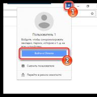
open program Macromedia Flash Professional 8, and create in it new document. Layers are created on the timeline by clicking the icon insert layer(insert layer). You can also choose from the menu to create a new layer. Insert - Timeline - Layer . This creates a normal layer. Perhaps you already did this when you created without a toolpath.
![]() But now you need a guide layer. It is created with an icon Add Motion Guide(add motion guide), or using the menu Insert - Timeline - Add Motion Guide
. Create it, you will have it on the temporary tape above the main layer. If the guide layer is lower, it will not work. In this case, you need to drag it up with the mouse.
But now you need a guide layer. It is created with an icon Add Motion Guide(add motion guide), or using the menu Insert - Timeline - Add Motion Guide
. Create it, you will have it on the temporary tape above the main layer. If the guide layer is lower, it will not work. In this case, you need to drag it up with the mouse.
Select the first frame in the main layer, from which the motion animation will begin, and if it is not a key frame, make it a key frame using the menu Insert - Timeline - Keyframe (or by right-clicking on it and selecting Insert Keyframe). Place an object on this frame. It can be an imported picture, a group of objects, or text. If you are importing an image, first prepare it in graphics editor, and then in Macromedia Flash select from the menu File -Import -Import to Stage . If the object is drawn, then group it using the menu Modify - Convert to Symbol .
Then select the last frame on the main layer, which will end the animation of the movement, and make this frame the key frame. On this frame, drag the object to the final position where it will be at the end of the tween.
Select the first frame in the guide layer, if it's not a keyframe, make it a keyframe, and place a motion path on it: select the first keyframe in the guide layer, and create a path with any tools that create a line. It can be a polyline, a curve, a part of a circle, and so on.
 After that, select the first frame, and drag the object to the starting point of the path. The object at the starting point must be fixed. You will see how it is attracted to the starting point - the outlines of the object will become thicker.
 In order for an object to be attracted in Macromedia Flash Professional 8, in the menu View-Snapping items must be included Snap to Guides(capture along the guides) and Snap to Objects(capture by objects). Also check if the item is enabled Snap Align(capture by alignment). Although the last point does not affect the attraction of the object to the trajectory, it is still better to include it too.
Now go Macromedia Flash to the end frame. Select it in the guide layer, and choose from the menu Insert-Timeline-Frame . An ordinary frame will be added, not a key frame (to add, you can also right-click on the frame, and select Insert frame). Thus, you will have a key frame on the final frame in the main layer, and a simple frame in the guide layer.
 After that, in the last frame, drag the object to the end point of the path. Next, you make a motion animation in Macromedia Flash: select some intermediate frame between the start and end, and in the panel Properties choose from the list Tween(fill frames) paragraph Motion(movement). If you want the object to rotate in the direction of the path, and not just move, turn on the item in the properties panel Orient to Path(if you do not see this property, click on the white triangle in the lower right corner of the properties panel).
Also in the properties panel in Macromedia Flash Professional 8 you can add the following properties for your tween:
 Scale(scale): If this option is enabled, if the size or shape of the object in the start or end keyframes is changed, then this change will occur smoothly during the tween.
Ease(slow down): used when you need to speed up or slow down the movement. To apply the option, move the slider up or down, or enter numbers from -100 to 100 in the box.
Rotate(rotation): objects during movement rotate clockwise or counterclockwise, The number of rotations of the object during the animation of the movement is written in the box.
Task: make a flash-movie with animation of movement along the trajectory. Here's what happened to me:
In this flash-movie, I used, in addition to the animation of the movement (ship), also (words) and (waves).
Video on how to animate motion along a path in Macromedia Flash Professional 8
You can get more detailed information in the sections "All courses" and "Utility", which can be accessed through the top menu of the site. In these sections, the articles are grouped by subject into blocks containing the most detailed (as far as possible) information on various topics.
You can also subscribe to the blog, and learn about all the new articles.
It does not take a lot of time. Just click on the link below: