Typically, a universal remote control (RC) is a small box with LEDs, circuits, and buttons. It works due to the fact that the infrared sensor on it transmits the desired code to the same sensor in another device. With it, for example, you can adjust the sound volume, switch channels, change the power of a device, and much more. It differs from the usual universal remote control in that several electrical appliances can be recorded simultaneously in its circuit. Today we will look at how to set up a universal TV remote control.
Setting up a universal TV remote
It will be pretty easy to do everything. It may not work the first time, but don't despair.
If you haven't bought it yet, you can buy it in China at a very low price.
The setting includes several ways:
- Press and hold SET (TV) until the red LED is active, then once on POWER, then enter the TV code and the indicator should turn off. If the indicator does not go out, then you must press the MULT button after entering the code.
- Dial the desired number and simultaneously hold SET (TV) and POWER.
- Hold SET (TV) until the red LED is active, then press POWER once, point the remote control towards the switched on TV and wait for its reaction. Then to the MULT button.
In the event that the device does not start to work, you need to try entering a different number for the existing TV model, or use the 3rd method.
If you don’t want to set up the remote control yourself or it doesn’t work, then you can ask an employee of some electronics store, you just need to know the TV code.
Setting up a universal remote without a code
In this method, you will have to do the settings yourself and without entering the number. To do this, you first need to turn on the TV. Then on the remote you need to hold down a button called Set for a few seconds, or it may still be SETUP (TV) until the red sensor becomes bright. Point your all-in-one towards the TV and press the green POWER button. The indicator should start blinking, which means the device has begun to select a code for your TV receiver. We are waiting for some kind of reaction to occur on the TV. For example, the sound will turn off, the channel will switch, etc., this reaction depends on the brand of the TV or even on the remote control. After waiting for the reaction, you must immediately press the MUTE button.
Pdf instructions for setting up the Rolsen remote control
Below is the official Rolsen tuning manual: RRC - 200, RRC - 300. It may be suitable for other devices.
After waiting a few seconds, the indicator will turn off and you can use it. If it didn’t work out, then try to turn off the sound after turning on the TV and after selecting the channel, and then do the same steps that are described just above. If you did everything correctly and your devices are really working, then the setup should be successful.
 Gone are the days when, in order to change TV channels on the TV, add sound to the tape recorder or rewind the cassette, you had to get up from the sofa and approach the actual knobs and switches on the electronic device. Of course, there was nothing wrong with that - once again raising your “fifth point” is very good for health, but still, technological progress is inexorable and thanks to it a remote control appeared, without which, in fact, the control of not one of modern electronic devices.
Let's see how this miracle of technology works. In fact, everything is quite simple, if you do not go into details. A remote control, for example, a tricolor TV remote control, does not perform any functionally complete task by itself. It works only in tandem with the device (TV, tape recorder, air conditioner) with which it is originally bundled or for which it is intended.
There is a microcircuit in the remote control itself, which converts information about the pressed key into a sequence of electrical impulses that are fed to the emitter (usually an infrared LED). In turn, the emitter transmits an already visually converted signal to a photodetector, which is located in the electronic device itself (TV, tape recorder or air conditioner). Having received information in a visual form, the photodetector converts it into a sequence of electrical impulses that are fed to the microcircuit of the device control unit. And it, in turn, already generates signals to control the functions of a TV, tape recorder or air conditioner.
That is, after you press one of the buttons on the remote control, the signal is first converted into a light form and then back into an electrical signal. The convenience of such a system is that with the help of a sequence of pulses (an electrical signal), a very large amount of information can be recorded. This allows not only to give the remote control more functional fullness, but also to use its own unique code for almost every electronic device, so as not to cause false alarms of other electronic devices that are not currently required to be controlled.
Infrared remote control is mainly used to control household electrical appliances.  management. This means that the transmission of the information signal from the emitter to the receiver is carried out in the infrared light range. The human eye cannot see in this range, so we do not physically notice the flickering of the emitter. On the one hand, this is very good - control signals do not interfere, for example, with watching a TV show. However, on the other hand, we cannot visually see whether the remote control is working or broken. But this is not such a big problem. To check the operation of the remote control, it is enough to have a mobile phone with a camera at hand. Turn it into camera mode and point the camera at the remote's LED. When you press any of the keys, the working remote control will emit periodic flashes that are clearly visible on the mobile screen. That's all.
Console, and... Russian spelling dictionary
remote controller- remote controller/ … Morphemic spelling dictionary
- (remote control, remote (remote) control) a device for controlling another device at a distance. Remote controls are used to control systems and mechanisms on mobile objects (aircraft, spacecraft, ships, etc.), ... ... Wikipedia
- (German rshch lat. pulpitum platform, tribune) 1) an inclined table, a footrest, 2) a control device (in the form of a table, a stand, a column), on which signal indicators, instrumentation and controls are placed, with … … Dictionary of foreign words of the Russian language
REMOTE, console, male. (German Pult from lat. pulpitum scaffolding) (special). 1. Music stand in the form of an inclined wooden or metal frame on a high leg, upr. instrumental music performers and conductors. Conductor's console. 2.… … Explanatory Dictionary of Ushakov
I m. 1. Tilt table, music stand; music stand 2. outdated. Desk with an inclined top board. 3. outdated. A glazed, removable, usually slightly inclined counter in a store. II m. Installation from the instrument system, allowing you to control on ... ... Modern explanatory dictionary of the Russian language Efremova
Exist., Number of synonyms: 13 Germanism (176) remote (2) lazy (28) ... Synonym dictionary
Console, a; pl. s, ov [non-remote, ov] ... Russian word stress
A; m. [it. Pult] 1. Stand for music on a high leg; music stand Conductor's item 2. Installation from the system of instruments to control the operation of something. P. flight control. Control room ◁ Console, oh, oh. (2 digits). P ow device… encyclopedic Dictionary
Books
- Destiny Remote, Peggy McCall. "Destiny Control Panel" is not just a book. It is an effective tool thanks to which you will miraculously change your life in a short time. How? The simple steps described here...
In general, a remote control (RC, RCU) is a wireless or wired device designed to control any mechanism, object or process at a distance. All remote control devices are divided into groups:
- according to the method of obtaining power supply: by cable, autonomous;
- on the channel used for transmitting control signals: IR, ultrasound, radio, wire, mechanical drive;
- by functionality: with one set of commands, universal for several devices of the same manufacturer, programmable (learnable);
- mobility and other characteristics.

The most common type of remote control at present is a mobile autonomous wireless device with object control via infrared (IR). It is this type of remote control devices that we use in everyday life when we transmit control signals to a TV, air conditioner, music center, player and other household appliances.
In the first models of consoles, there was a minimum of control elements only for performing basic functions. Over time, the approach has changed: modern products have a full set of controls, while the controlled devices themselves contain a limited set of them.
Remote control device
The gadget is a small oblong plastic box. On its front part there are buttons with the help of which the choice of the control command is carried out.

At the end of the device there are holes for the lens of the IR emitter, which directly sends the command for execution. On the reverse side, under the cover, there is a niche for installing batteries. As a rule, these are two AAA batteries.

If you disassemble the remote control, disconnecting its upper part from the lower one, then we will see two more elements. The first is a printed circuit board with contact pads and mounted electronics.  The second is an overlay made of soft elastic material with convex control buttons with conductive discs.
Infrared wireless remote control: how it works
The device of the remote control and the operation of the remote control are based on one-way or two-way transmission of information between the remote control and the control object using light rays in the infrared range. IR receivers and transmitters are used to receive and transmit signals.
The control panels that control air conditioners have a scheme with a two-way information transmission channel: a control signal is sent to the air conditioner, and the operating parameters of the unit and temperature data are returned back.

All other models in the vast majority of cases are single-channel.
Sending and receiving commands
Let's take an operation that is most common in everyday life: remote wireless control of a TV. The first thing the remote circuitry does is determine which button has been pressed. The principle of definition is the same as in a computer keyboard: scanning a matrix of placed buttons. But, unlike the PC keyboard, on the remote control scan generator is in standby mode and turns on only when you press the buttons on the remote control. This achieves economical use of batteries.
Then the control signal (command) is encoded and transmitted by an IR LED. Before the transmission of the main signal, the transmitting and receiving devices are synchronized, and on the receiving side, the code of the remote control is checked for compliance. The transmission itself will be carried out for the entire time while the control button is pressed.
It should be noted that manufacturers of electronic devices are not limited in any way in creating algorithms for coding control signals and the modulation frequencies used. This leads to the fact that often even the same type of models from the same manufacturer require different control panels for control.
Remote control diagram
Most schemes for TV remote controls and other household devices are basically based on microchip, which generates a control signal after pressing the corresponding key, signal amplifier And IR LED. The difference lies only in the name and layout of the radio elements inside the device case and on the printed circuit board.

A microcircuit is a specialized microcontroller into which a program code is written during the production process. The recorded program is then no longer changed during operation. The board also contains quartz resonator to synchronize the frequency of the receiver and transmitter. The signal amplifier is part of the microcircuit or is made on a separate element.
To create such a device yourself, in addition to amateur radio skills, you also need to be able to create program code for microcontrollers.
Remote control for PC
A remote control for a personal computer can be useful when working with the interface of both the operating system itself and when controlling the functioning of various programs. For example, managing presentations in power point or playback of media content in media center. Sometimes such remotes are already included with the PC.

Manufacturers of remote controls for PC, unlike TV, have implemented 2 solutions: IR and radio remotes. The fact is that when controlled in the infrared range, it interacts with the device in direct line of sight and at a distance of up to 10 m, which is sufficient for TV, but may be inconvenient for PC control, especially during presentations. The radio remote control increases this distance to 30 m, regardless of obstacles in the signal path.
Externally, the radio remote control will differ from the IR only in the presence of a small antenna. But in order to be able to control, a PC needs one more element: a radio or IR signal receiver installed in a computer or laptop. It can be either a built-in device or a module connected to a USB port. The second option is preferable.
Universal and/or programmable remote control
A universal remote control may be required in two cases:
- A replacement for a lost or broken old TV remote control or other household appliances has not been found.
- A lot of different household appliances in one room makes it extremely inconvenient to control it from different remote controls, since the concept of “correct design” and “optimal ergonomics” is different for all manufacturers.
There are two types of such devices: remotes that store commands (learners), and programmable universal remote controls. In the first case, to enter the necessary codes, a regular TV remote control or other device is used. In the second, the list of available codes and models of equipment that can be controlled is in the instructions for the control device. The difference is that, despite the thousands of device models supported by universal remotes, the device you need may not be in this list.
"Learning" of memory remotes is carried out in accordance with the user's manual and using the original remote control. If the purchased remote control has fewer keys on its front panel than the “native” one, then first of all, only those that are needed should be programmed.
After acquiring a universal multifunctional remote control, you should not throw away the old regular ones. Firstly, they may be required if the new one suddenly fails. Secondly, some necessary elements may not be on the universal one. And thirdly, they may be required for reprogramming in the event of a failure or change of batteries.
Smartphone as a remote control
Another remote control option for almost any device is using a smartphone as a control device. At the same time, it may or may not be able to transmit signals in the IR range (technology IrDA). In the latter case, control is carried out via Bluetooth or Wi-Fi. The only limitation is that the managed device must also support these communication protocols, which is not implemented on all equipment.
More interesting as a remote control option is a smartphone with an infrared port. Let's take a look at this model Xiaomi Redmi 3 and a rather old TV Daevoo. We need to install from Google Play special application. It can be anything, the main thing is that the list of supported equipment should include the model of the control object. For this phone with a shell from MIUI it's called Mi Remote(Russian language is present).

Modern stationary and portable household equipment - cameras, video cameras, air conditioners, TVs, music centers, home theaters, etc. for convenience, can be controlled from a distance using remote control systems (RCS) built into the equipment. A wireless infrared remote control system, the principle of which we will consider in the material of this article, has become a little widespread.
To consider in detail and in detail the question of how the wireless remote control system on infrared rays works, we will be helped by the SDU-15, which was used in the 3rd generation TVs 3USTST. You can get acquainted with the principle of operation of the remote control for more modern models of household appliances on the page - http://www.xn--b1agveejs.su/bytovoi-tehniki/statyi/250-pdu-saa1250.html
SDU-15 - infrared remote control system
The remote control system for Soviet 3rd generation televisions 3USCT includes an autonomous control panel PDU-15, as well as an infrared radiation receiver PI-5 and a remote control module, MDU-15, built into the TV.
The remote control system allows you to switch TV programs, adjust the brightness, contrast and saturation of the image, as well as change the volume of the soundtrack, turn the TV on and off. The adjustment time from the minimum to the maximum value (or vice versa) does not exceed 12 seconds.
The TV can be controlled from a distance of 0.3 to 6 meters. The angle of operation of the remote control system in the horizontal and vertical planes is ±30°, and the angle of view of the receiver in the horizontal plane is ±45°.
On the control panel, the transmitted commands are encoded and modulated into short pulses of infrared (IR) radiation. The commands are sent to the receiver, from where, after appropriate processing, to the remote control module. From the remote control module, commands for switching programs are sent to USU-1-15-1, and to perform operational adjustments - to the control unit.
To be able to turn the TV on and off from the remote control, it is put into standby mode by pressing the "Network" button. In this case, the mains voltage is supplied only to the SDU-15 module. An indication of the operation of the TV in standby mode is highlighted by an indicator on the front panel. The TV is switched to the operating mode by pressing any of the eight program selection buttons on the remote control or the TV power button on the front panel. Pressing button 2 causes the relay in the remote control module to operate, and through its contacts the mains voltage is supplied to the filter board and the switching power supply of the 3USCT TV.
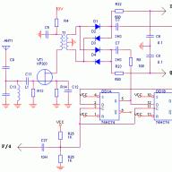
Remote control PDU-15 for 3USCT TVs, diagram and principle of operation

Rice. 2 Schematic diagram of the remote control PDU-15
The remote control PDU-15 is designed to form electrical signals in accordance with control commands, amplify them and emit them in the form of modulated pulses of infrared radiation. Short pulses of infrared radiation with a duration of 10 μs are modulated with a binary code in such a way that the time interval between their emission varies. So logical 0 (low level voltage) corresponds to the main time interval T (for example, T \u003d 100 μs), and logical 1 (high level voltage) - 2T.

Rice. 3.
The required information, in accordance with the control command, is transmitted by eleven pulses (Fig. 3). In addition, each signal of the remote control system contains start and stop pulses. The time interval between the first and second is equal to 3T, between the triggering and the first information pulse T. Five pulses are assigned to transmit the address and six to transmit the command. Obviously, after pressing the corresponding button on the remote control, depending on the transmitted address and command, the duration of the intervals, T or 2T, will change. The last information pulse is followed by a stop pulse after the ST interval. The control panel uses an IC type KR1506KhL1 specially designed for this purpose (Fig. 2). The operation of the IC is determined by the clock generator, the pulse frequency of which is set by external elements R1, C1, connected between its terminals 2 and 3. Resistor R2 reduces the effect exerted by fluctuations in the supply voltage on the frequency of the generator. The time constant of the circuit R2, C1 is selected depending on the frequency of the quartz resonator used in the PDU-15.
When you press one of the buttons (S1 - S16) on the remote control, one of the pins 10, 13, 15 is connected to one of the pins 16-23 of the IC. Each such connection generates a certain command in the IC, i.e. a sequence of pulses that appear at its output 5 (see table below).
| Button remote control |
Code data |
Executable function | connectable IC output |
| S1 | 000001 | Power off | 15-22 |
| S2 | 000011 | Setting working values for brightness and saturation | 15-20 |
| S3 | 010000 | Turn on 1 program / turn on the power | 13-23 |
| S4 | 010001 | 2 programs on/power on | 13-22 |
| S5 | 010010 | Turn on 3 programs / turn on the power | 13-21 |
| S6 | 010011 | Turn on 4 programs / turn on the power | 13-20 |
| S7 | 010100 | Turning on 5 programs / turning on the power | 13-19 |
| S8 | 010101 | 6 program start/power on | 13-18 |
| S9 | 010110 | Turning on 7 programs / turning on the power | 13-17 |
| S10 | 010111 | 8 program start/power on | 13-16 |
| S11 | 101000 | Increase brightness | 10-23 |
| S12 | 101001 | Decrease brightness | 10-22 |
| S13 | 101100 | Increasing saturation | 10-19 |
| S14 | 101101 | Desaturation | 10-18 |
| S15 | 101110 | Volume up | 10-17 |
| S16 | 101111 | Volume down | 10-16 |
In addition to IC D1 and buttons S1 and S16, in the circuit of its control inputs, PDU-15 contains a power amplifier based on transistors VT1, VT3, VT4, loaded with IR radiation diodes VD3 - VD5, and a voltage doubler on the key transistor VT2. The need to use a power amplifier is caused by the fact that the output stage of IC D1 is capable of delivering a current of no more than 10 mA to the load, and to obtain the required range through the emitting diodes VD3 - VD5, a current of about 1 A is required.
A characteristic feature of the amplifier is that in the absence of an input signal, all its transistors are closed. The current consumed by the amplifier in this case is determined only by the leakage currents of capacitors C2 and C3 and does not exceed 50 μA. This made it possible to abandon the use of a power switch. While the command buttons S1 - S16 are not pressed and in the pauses between pulses, the capacitors C2, C3 are charged to a voltage close to the voltage of the battery G1 (9 V), respectively, through resistors R4 and R8. In this case, the transistor key VT2 is closed by a positive voltage applied through resistors R4 and R5 to its base. When one of the buttons on the remote control is pressed, positive pulses from pin 5 of the IC arrive at the base of the emitter follower VT1 and open it. This, in turn, causes the opening of the transistor VT3, the base of which receives positive pulses from the emitter VT1.
A positive signal is taken from the emitter of the transistor VT3 to control the current source, and a negative pulse is taken from the collector to control the key VT2. The transistor key opens, and the capacitors C2 and C3 are connected in series through the emitter and collector junctions VT2. As a result, almost twice the power supply voltage is applied to the output stage on the VT4 transistor.
Diode VD2 prevents the discharge of the capacitor C3 through the power supply and resistor R4. Transistor VT3, together with the zener diode VD1, forms a constant current source, designed for a load current of 1 A. At the same time, the current through the diodes practically does not depend on the spread of the voltage drop across them and on the state of the battery, which allows you to maintain a constant radiation power.

Rice. 4. The appearance of the remote control:
1 - emitter of infrared rays; 2 - buttons for selecting programs and turning on the TV (8 pcs.); 3 - volume buttons; 4 - brightness adjustment buttons; 5 - saturation adjustment buttons; 6 - "Normal" button for setting saturation and brightness to the middle position; 7 - button to turn off the TV (transfer to standby mode); 8 - power compartment cover.

Rice. 5.
The circuit diagram of the receiver is shown in fig. 5. To receive infrared signals, a VD1 photodiode is used - a photovoltaic receiver that has one-way conductivity when exposed to radiant energy. It is a semiconductor receiver consisting of three alternating p-n-p conduction regions. The base serves as a receiving platform for radiation. When a photodiode is irradiated with a modulated infrared beam, a current flows through it, which coincides in shape with the IR radiation signal.
The electrical signal is amplified by a pre-amplifier on transistors VT2 - VT5. Transistor VT1 is a dynamic load of the photodiode and is designed to suppress the constant background of ambient radiation created by the operation of incandescent lamps, fluorescent lamps, etc.
From the collector of the transistor VT1, the electrical signal enters the first stage - the emitter follower VT2, the mode of which is set by the elements R2, R5, VT1. The current-amplified signal from the emitter of the transistor VT2 enters the base of the transistor VT3 - the second stage, is amplified in voltage, inverted and fed to the third stage of the VT4 amplifier. The modes of the second and third stages for direct current are determined by resistors R7, R4, R3 and RIO, R9, and for alternating current - by resistors R7, R6 and R10, respectively. The collector loads of the cascades are resistors R8 and R11.
From the emitter of the transistor VT3, a negative frequency-dependent feedback signal is removed to suppress the background of ambient radiation. The low-frequency background voltage is selected by the low-pass filter R7, C2, R6 and R4, CI, R3 and is fed to the base of the inverter VT1. Resistor R1 sets the current mode of the transistor VT1.
Selected on the load of the third stage - resistor R11 - the pulse code signal through the isolation capacitor C4 is fed to the limiter VT5, VD2, which is necessary for signal selection against the background of noise and interference with an amplitude below the threshold. From the load of the transistor VT5 - resistor R13 - an amplified inverted signal through pin 3 of connector XI is fed to the remote control unit A30.2. Resistor R12 is used to close the transistor VT5 in the absence of a signal, and the diode VD2 is used to temperature stabilize the voltage on its collector.
Remote control module MDU-15

Rice. 6. Schematic diagram of the MDU-15 remote control module. (The denominator shows the voltages in the absence of a command.)
From the output of the infrared radiation receiver, the signal through contacts 3 of connectors XI (AZO.Z) and X2 of the MDU-15 module is fed to pin 16 of the IC D1 chip of the KR1506KhL2 type.
The clock frequency is generated by a BQ1 quartz resonator connected between terminal 23 of the KR1506HL2 microcircuit and the positive pole of the power source. Four digital-to-analogue converters (DAC) in KR1506HL2 (DA1 - DA4) generate a rectangular voltage with a frequency of approximately 17.3 kHz at terminals 2-5 of the IC, the duty cycle of which varies (the duty cycle of rectangular pulses is the ratio of the period to the pulse duration, and the steps are the limits of the duty cycle change ). Outputs 2, 4, 5 of the DAC are used to control the levels of brightness, saturation, volume.
When commands are given to increase or decrease the level of brightness, saturation or volume, the duty cycle of the rectangular voltage begins to change at the corresponding output DA1, DA3, DA4 (pins 2, 4, 5) of the IC (see waveforms 8a, 86, 8c in Fig. 7). A full cycle of duty cycle changes occurs in about 12 s. From pin 2 of IC D1, when button 11 or 12 is pressed on the remote control (see the MDU-15 diagram), through the divider R3, R7, the pulse voltage is supplied to the RC filter R12C5 and then to the input of the operational amplifier - pin 2 AND C D4. From the output of the amplifier (pin 13 of IC D4), the final signal through resistor R23, pin 6 of connectors X6 and X7 (A30), contacts of the S2 button in the control unit BU-3-1, pin 1 of connector X5 (A2) enters the brightness control circuit color module.
From pin 4 of IC D1 (with the buttons S13 or S14 pressed on the remote control) through the divider R4, R14, the pulse voltage is supplied to the RC filter R15, C6 and then to the input of the operational amplifier - pin 6 of IC D4. From the output of the amplifier (pin 9 of the IC), the final signal through the resistor R24, pin 7 of the connector X6 and X7 (AZO), the contacts of the button S2 in the control unit, pin 2 of the connector X5 (A2) is fed into the saturation control circuit of the color module.
From pin 5 of IC D1 (when buttons S15 or S16 are pressed on the remote control), the signal through the divider R5, R8, C7, pin 1 of connectors X6 and X7 (A30), pins 13, 14 of the S2 button in the control unit, pin 6 of connector X9 ( A1) enters the volume control circuit of the TV radio channel module.
The D4 integrated circuit of the K157UD2 type is designed to match the large output impedance of the D1 IC with the load in the brightness and saturation control circuits. When the supply voltage is applied to the D1 IC, the internal DACs 1-4 are set to a position (see waveform 86 in Fig. 7), which corresponds to the average value of brightness and saturation.
Program switching commands - pressing the buttons S3 - S10 on the remote control lead to the appearance of voltage pulses on the terminals 8-10 of the IC D1 (outputs PA, PB, PC of the program number code register) that are applied to the control inputs A0, A1, A2 (pins AND , 10, 9) IS D2 type K561KP2 (see table).
| Program number | Output voltage, V | ||
| 8 (RA) | 9 (RV) | 10 (RS) | |
| 1 | 0 | 0 | 0 |
| 2 | 12 | 0 | 0 |
| 3 | 0 | 12 | 0 |
| 4 | 12 | 12 | 0 |
| 5 | 0 | 0 | 12 |
| 6 | 12 | 0 | 12 |
| 7 | 0 | 12 | 12 |
| 8 | 12 | 12 | 12 |
Depending on the code, i.e. combination of these pulses, a voltage pulse of 12 V appears at the corresponding output of IC D2, which, through connector X1 (A10.X2), enters the USU-1-15-1 device and turns on the selected program. When power is applied, at the moment the SDU is turned on, the program number code register is in its initial state and the first program is turned on.
The remote control system uses autonomous power sources for its operation: a 9-volt battery of the Krona type on the remote control and a stabilized rectifier in the MDU-15 module, consisting of elements T1, VD1, SZ, D3, R19, VD2, C11, C12. When the mains voltage is turned on with the S1 button on the remote control, the TV is switched to standby mode. The mains voltage through the closed contacts of the button S1 in the control unit A9, contacts 1, 3 of the connectors X17 (A30) and X4 (A9) is supplied to the primary winding (pins 1, 2) of the transformer T1. The voltage taken from the secondary winding (terminals 3, 4) of the transformer is rectified by a block of silicon diodes VD1, smoothed by the capacitor C3 and fed to a 12 V voltage regulator made on D3 elements of the KR142EN8B, R19, VD2 type. Connecting pin 8 of the D3 voltage regulator chip to the case allows you to get a bipolar voltage source: 12 V and - 6.2 V. The VD2 zener diode provides a stabilized voltage of 6.2 V, the R19 resistor determines the rated current of the VD2 zener diode. Capacitors C11, C12 eliminate the excitation of the stabilizer.
To control the device for turning the TV on and off in standby mode, the internal trigger of IC D1 (pin 19) is used. Turning on the TV is carried out in one of two ways, in each of which the trigger N (pin 19) is transferred to such a state that a voltage of 12 V is established at pin 19 of the IC. The first way is to send any of the eight program selection commands from the remote control; the second way is to press the S4 button (“Turn on the TV” on the control unit). In the second method, a voltage of 12 V appears at pin 19 of IC D1 for at least 10 seconds. The 12 V source is connected to pin 19 of IC D1 via the following circuit: pin 2 of IC D3, pins 4 of connectors X5 and X5 (AZO.Z), pins 2 and 3 of the S4 button in the control unit, pins 3 of connectors X5 (AZO.Z) and X5 , resistor R27, pin 19 of IC D1. The positive voltage from terminal 19 AND C D1 through the circuit R27, R29 enters the base of the transistor VT4 and opens it. Through the winding of the relay KV1.2, included in the collector circuit of this transistor, current begins to flow. The KV1.2 relay contacts close the mains voltage supply circuit to the A12 power filter board of the 3USCT TV power supply.
When a command is given to turn off the TV by pressing the S1 button on the remote control, the trigger N in the D1 IC is reversed, and a negative voltage is set at its output (pin 19 of the IC), which, acting through resistors R27, R29 to the base of the transistor VT4, closes it. The current through the relay winding KV1 stops, the relay contacts open and turn off the mains voltage from the contacts of the connector X7 (A12). The TV turns off (puts into standby mode).
To indicate the operation of the remote control device, a single vibrator assembled on transistors VT2, VT3 is used. In standby mode, after turning on the mains voltage, the transistor VT2 is closed, since the potential of its base is lower than the potential at the emitter, and the transistor VT3 is open. Transistor VT3 closes the circuit: 12 V source, resistor R26, collector-emitter junction of transistor VT3, diode VD3, pin 10 of connector X6 (A9) and X7 (A30), indicator LED HL3 in control unit A9, housing. The glow of the HL3 indicator in the control unit indicates that the TV is in standby mode.
When the TV is turned on, the transistor VT4 opens, the potential on its collector becomes close to zero and overturns the single vibrator: the transistor VT2 opens, and VT3 closes, the HL3 indicator on the control unit does not light up.
Any command transmitted by the remote control and received by the D1 IC appears at pin 17 of the D1 IC in the form of a sequence of negative pulses (see waveform 7 in Fig. 10.8), which are fed from the divider R17, R22 to the start input of the single vibrator - the base of the transistor VT2. The first negative pulse overturns the single vibrator, while the transistor VT2 closes, VT3 opens, closing the power supply circuit of the HL3 indicator to the control unit. The duration of the one-shot pulse is set by the positive feedback circuit C10, R18 together with the input divider R17, R22 and is equal to 1/16 s. The single vibrator works all the time while negative pulses are received from output 17 of IC D1 to base VT2, i.e., while any button on the remote control is pressed. This ensures the intermittent glow of the HL3 indicator.
From the emitter circuit of the one-shot through the resistor R21, the control signals are fed to the base of the transistor VT1, which, together with the elements R16, R4, forms an integrator designed to maintain a zero potential at the input V (pin 6) of the IC D2 during the issuance of remote control commands. When the remote control commands are not given, the transistor VT1 is closed and a positive charging potential of the capacitor C4 through R16 is set at the input of the microcircuit, which allows you to switch programs manually from the front panel of the TV.

Rice. 7. The shape of pulses and oscillograms on the elements of the remote control system. (Waveforms 2-5 are shown when the S3 button is pressed when the first program is received; waveform 8 is shown for three levels.)