Below is a compilation of several materials from the web
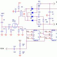
Simple SDR Receiver with Diode Mixer
A source follower is assembled on T1. Crystal oscillator on T2-T3. The oscillator frequency must be four times the frequency of the received signal. For the 80m band, I used quartz at Fq = 14.7456 MHz. The crystal oscillator is assembled according to the UT5UDJ scheme on. If you reduce the capacitance C20 to 15-20 pF, the generator, according to the description, will be excited at the third harmonic. Therefore, in theory, you can use quartz Fq * 3/4 = Fc, where Fc is the desired receive frequency +/- 24kHz or 48kHz, depending on the computer sound card used (I did not check it).
With a construction resistor R15, you need to set the "middle point" - 1/2 of the supply voltage, and R16 equalize the gain of the op-amp in both channels. 157UD2 was used as an op amp in the original circuit, but I didn’t have it, so I installed NE5532. The signal to the computer's sound card is removed from the connector. I assembled the circuit on a breadboard. On the very first evening I heard many stations from Europe: SP, YO, LZ, DL, OH, OZ, the European part of Russia, Ukraine, etc. I think the circuit is simple, does not contain rare parts and may be an option for those who want to get acquainted with the SDR technique. I checked the work with many SDR programs - it worked with all: FlexRadio 1.6.2, SoftRock, Winrad, SDRadio. Sound card integrated by Realtek.
Congrats Leodan! Successful design. At the input, it is desirable, of course, to put a band-pass filter, but these are particulars. K2PAL You are not far from the truth, V.T.Polyakov also had a hand, or rather a thought, in this mixer. Address of Sergey's article (US5QBR) on key diode mixers http://www.cqham.ru/kds.htm
In no way do I claim copyright. It's just that people buy softrock "and, but not everyone has the opportunity to quickly buy and try it, but they really want to. Many people have these details, so you can try it without waiting for weeks for mail. I haven't soldered it for 10 years, but then I took something in hands soldering iron and that the most interesting thing worked. And V. T. Polyakov can be safely indicated in every post on the forum on direct conversion technology and SDR. I have the entire collection of his works on my bookshelf. I have never seen it easier.
A very good and workable circuit, but the SDR transceiver circuit was even simpler. There, each mixer was on two diodes. On the same forum there is a photo of the manufactured device.
Schematic diagram of the SDR transceiver

Yes, that's the mixer circuit. On the forum, the site in the topic "Single-band QRP SDR transceiver" UR0VS laid out a transceiver circuit with such a mixer, there was a small error in the circuit, and apparently that's why he removed it. The photo of this device remained on page 3 of this forum. The above mixer circuit is reversible and if a quadrature low-frequency signal is applied to the I and Q points, then this will become a transmitter. Of course, the source follower in this case must either be removed or "bypassed". By the way, it is not necessary to install this source follower, the sensitivity will be quite high even without it. It will also be very useful to introduce balancing circuits into the mixers.
All success! Yuri.
Good evening Vladimir Timofeevich, I am flattered by your attention! Here is the exact link to the crystal oscillator circuit:
http://rf.atnn.ru/s4/urt-8oo.html Checked again - there are no errors. Yes, and it works, right now on the table.
I don't know how...
A small correction of the scheme in my first message. When using a 24-bit sound card at +/- 48kHz, gain unevenness over the range is noticeable. What's good for the receiver is bad for SDR - the bandwidth must be much wider than 3kHz. Therefore, it is advisable to replace capacitors C5, C6, C7, and C19 with a smaller value - 0.01 nF or even less. I removed them completely, but I think that there may be problems with overloading the op-amp from powerful out-of-band signals. As a result, the frequency response has become much more uniform - there are no blockages at the edges of the range.
Loopless crystal oscillator
V. ARTEMENKO (UT5UDJ), Kiev.
In amateur radio practice, the problem of obtaining highly stable oscillations in frequency is relevant. Usually, crystal oscillators are used for these purposes. The industry produces quartz up to frequencies of at least 100 MHz. If a radio amateur has quartz for a frequency, for example, 27 MHz or 45 MHz, this does not at all guarantee that such a generation frequency will be obtained. In most cases, quartz at frequencies above 20 ... 25 MHz is harmonic (most often it is the 3rd harmonic). This means that a quartz that has an inscription of 27 MHz will actually generate at a frequency of 9 MHz, and a quartz with an inscription of 45 MHz will actually generate at a frequency of 15 MHz.
Therefore, in many circuits discussed in the literature, a resonant LC circuit is used, tuned to a frequency of 27 or 45 MHz. Typically, such an LC circuit is included in the collector (or drain for a field-effect) transistor.
In addition to the complexity of tuning the LC circuit itself, in this case it must be shielded, since at such frequencies it is a source of interference. In addition, when operating an LC circuit for a low-resistance load, a good buffer stage is also needed. As a result, it was proposed to do without an LC circuit when working with harmonic quartz. However, testing the circuit performance showed that none of the tested quartz (more than a dozen different harmonic quartz were tested) was excited at the 3rd harmonic. Moreover, even those quartzes (on the 1st harmonic) that work reliably in other circuits do not work in this circuit. In this regard, the author does not recommend using the scheme in amateur radio practice.
At the same time, analyzing in detail numerous circuits of 27 MHz portable radio stations, you can see that when using the K174PS1 (K174PS4) chip and 27 MHz quartz, you can do without an LC circuit. The author effectively used this important conclusion when developing his oscillator circuit, which works on the same principle, but on discrete elements, since it is rather inconvenient to use these microcircuits due to the impossibility of obtaining a 50-ohm output without the use of buffer stages.
In the proposed circuit, the output impedance is approximately 50 ohms.

The operation of ZQ1 quartz in the circuit is possible both on the main and on the 3rd harmonic - depending on the capacitance of the capacitor between the emitters of the transistors (C4).
With a capacitance of the order of 100 pF (the capacitance should be selected), most quartz works on the fundamental harmonic, i.e. quartz, on the body of which it is written, for example, 27 MHz, generates at a frequency of 9 MHz. However, at a capacitance of about 10 pF, generation is observed directly at the 3rd harmonic, i.e. we get the frequency that is written on the case of this quartz.
In the proposed scheme, with such a small capacitance of C4, even non-harmonic quartz is generated at the 3rd harmonic, i.e. designed to work only on the 1st harmonic. This is especially true for quartz with frequencies below 20 ... 25 MHz. So, for example, quartz with an inscription on the 6 MHz case at C4 "100 pF normally generated this frequency (6 MHz), but when C4 was reduced to 10 pF, it also began to generate at a frequency of 18 MHz! As it turned out, at least a third of such non-harmonic quartz crystals can be made to generate at a frequency 3 times higher than indicated on their case.
It is also worth noting that even those quartzes (both at the 1st and at the 3rd harmonic) are normally excited in the proposed scheme, which usually do not generate in other schemes (low active).
Setting up the circuit with serviceable elements consists only in selecting C4 to obtain the required generation frequency. To do this, through a 50-ohm attenuator, we connect a frequency meter to the output of the circuit, and select the capacitance C4. At a 50-ohm load, the circuit at Up \u003d 12 V produces an RF voltage of about 200 mV. There are, unfortunately, quartzes that "do not want" to work on the 3rd harmonic (with the frequency that is written on the case). These are mainly imported miniature quartz, where, probably, not quartz itself is used as a working material, but special ceramics.
Literature
1. Poliakov V. Stable quartz oscillator. - Radio, 1999, N6, p.62.
RL 8/2000, p.27.
It seems to me that this generator can be used in balanced mixer circuits, where antiphase local oscillator voltages are needed, since such signals should be on the collectors of the generator transistors. But, I can’t check the assumptions - only a tester is available from the devices.
The operation of the generator can be explained as follows: mentally draw small capacitances between the bases and emitters of transistors - you will get two capacitive three-points connected on both sides of the quartz, therefore, they are excited out of phase. For three-points from emitters, the conductors should go to ground, but since the emitters are out of phase, I will replace two conductors to ground with one, between the emitters.
For this case, the scheme is redundant. You can discard T2 and related resistors R17...20. Released conclusions of quartz and C20 - ground. And to make the excitation more stable and reliable, add a 10 ... 20 pF capacitor between the base and emitter of the remaining single transistor T3. This single-cycle oscillator is also excited on the 3rd harmonic of the quartz, if you don’t install an additional capacitor, and replace C20 with a 6/25 or 8/30 pF trimmer and twist it to the maximum amplitude (I remembered that I did such an experiment a dozen and a half years ago ... ).
A push-pull generator will work with an LC circuit, the following modifications are needed: we replace the quartz with a series circuit of a coil and a 50 ... hands, because they are not grounded and under high-frequency voltage). We include capacitors of approximately 470 pF between the base and emitter of each transistor in order to weaken the influence of unstable junction capacitances, and the capacitance C20 must also be increased to 200 pF or more (for the same purpose).
In general, the circuit is not bad for beginners, just right, and most importantly, on an accessible element base.
I agree with Vladimir Timofeevich that a simpler local oscillator circuit can be applied, but the choice of this particular heterodyne variant was quite conscious, because. I wanted to test the claimed UT5UDJ ability to be easily excited on the 3rd harmonic of quartz.
For LeoDan, you can find out the approximate reception characteristics, well, in general, approximate comparisons with such devices of this class. I will be very grateful!
For RA3XCS. So far, unfortunately, there is nothing to compare. But soon such an opportunity will appear. I received the SoftRock 6.0 kit and almost assembled it. In the coming weekend I will try to compare the receivers in the same conditions. I can record .WAV files and post them somehow. They can then be played using the Rocky 1.5 program: http://www.dxatlas.com/Rocky/
True, I have, to put it mildly, a "very" surrogate antenna, but I also heard Europeans DL-DK, I, OH, SM of course SP, European Russia (1,3, 6 regions), Ukraine, Belarus.
For LeoDan, well, as they say, we'll wait, but what kind of software are you using, is it SDR. For RA3XCS. Well, I assembled SOftRock v6.0, but I used the same quartz as in the designs from the first page. To be honest, I didn't notice much of a difference. I can post IQ files recorded with Rocky 1.5 http://www.dxatlas.com/Rocky/ which works as SDR radio too. Sampling rate 48Khz. True, these files weigh 1.5MB and 1.5MB and contain only a few seconds of recording.
As for the software used, as I already wrote, I checked it with many: Rocky 1.5, PowerSDR 1.6.3, WinRad, SDRadio, it works with everyone, only for my Sound Blaster Audigy card PowerSDR required the installation of ASIO drivers, for 24Bit / 96kHz.
For ur3iag. SoftRock v6.0 was received purely by accident. My work colleague, a familiar radio amateur from England, presented it to me. So I can't help with the purchase, alas.
Attachments softrock_6_183.rar (1.48 Mb)
For RA3XCS. Good luck! The design of the mixer was developed by serious people, including V.T. Polyakov. Therefore, in my opinion, everything should work well.
In defense of the design on diodes, I can say that, unlike SoftRock v6.0, everything was assembled at the assembly line, with long wires without any shielding from computer and other interference. So, I think if you assemble it on a signet, everything will be OK in a shielded case. Oh, and don't forget to reduce capacitances C5-C7 and C19 to 3.3nF or even 1nF.
Collected this scheme. Thanks to the authors, a simple solution, done on a breadboard in one evening, and honestly works. To be honest, I did not notice unevenness at the edges of the 48kHz range, with filter capacitances of 0.1m. I noticed that a fairly strong station (carrier) is received "mirror-like" and it was possible to minimize it by fine-tuning the gain of one channel (R16), but it was not possible to completely get rid of it. The carrier from a nearby working quartz oscillator still draws two columns, one large and the other small. What else can you pick up, adjust? Although here he himself thought maybe this is the "crawling" of one channel of the sound into another, you need to try that the thread is of better quality.
To Richi, you still need to twist the phase. Gain and phase are corrected in the programs, it is not necessary to equalize the gain
hardware channels. Good luck! Yuri.
For Richi. If you are using Rocky 1.5, then there are several options for customization:
1. Try to delay the signal in the right channel. See attachment 1. In my case, the -1 delay helped to get rid of the mirror channel radically, at least visually and aurally.
2. Set the automatic balancing of the difference in phase and amplitude. From the menu: Tools / I / Q Balance. Birds mark Collect data and Correct balance in the lower left corner. See attachment 2.
Other programs also contain similar gadgets.
Dear Colleagues! I would venture to suggest a variant of the printed circuit board of the SDR receiver, the diagram of which is presented on the first page of the forum. I haven't implemented it yet, because I don't have the time. In essence: the board is drawn from the side of the tracks, so for the laser-iron method, do not forget to set the "mirror" function. The 5 volt stabilizer 78L05 is compact. The DPF was not bred deliberately, it’s for each one for its own frames and antenna connector itself, I think there is enough space. Numbering of parts according to the scheme. On the board there are extra nickels in some places, done deliberately, for different sizes of components. Write about the noticed shortcomings in the forum.
Good luck!
Mini SDR Transceiver
Hello everyone, well, in general, the signet is not bad, so it must be implemented. And here is another interesting project that can work on the transmission of a mini transceiver.

And how would something similar be built on 144 and 433?
And how to form a heterodyne voltage? Yes, and the dynamics there is not particularly needed. There you can just have two mixers and a quadrature obtained from the harmonic voltage with the help of a DL (this is for 430 or 1260 MHz) ... Well, the design is gradually taking on a finished look. Thanks EX117!
I have a question: There is an SDR receiver. On the air, I watch RTTY or CW work. In what "way" can a teletype, telegraph or other type of modulation be decoded using the program, let's say RTTYGet? Do you need a second sound card to input the sound demodulated by SDR?
What is VPD?
VPD are back-to-back diodes.
I don’t know about 144 and 430, but for higher frequencies, for example,
people do like this: http://www.ljudmila.org/hamradio/notune.html
Then, in the light of the facts revealed to me, 45grd can be obtained:
by another division by 2,
by applying a 45deg phase shifter () (of the same single RC arm)
by applying a DL segment that shifts the phase by 45 deg.
In general, nothing new. But one question worries me: where in this thread did I miss the mixer on anti-parallel diodes?
The circuit from LY1GP uses these SMs, presented at the link K2PAL. In the SSB receiver at 160m W.T. Polyakov also did it in a similar way, but in the scheme from LY1GP one more link was added and a shift of 0 and 90 was indicated. This moment interests me. Isn't this a mistake. Attached diagram for clarity.
Greetings to all.
Yuri, in the presented scheme from LY1GP, there are no errors. Please note that 2 RF phase shifters are used there - at the mixer input from the signal side and at the GPA input, i.e. this PV actually consists of 2 links (2nd order), somewhat spaced apart in space. And it works on the difference (sum?) of the introduced phases of each link. It must be assumed that this inclusion improves the accuracy of the PV, but this is only a guess. It was interesting to know the opinion of the author on this matter.
No, at the input the signal is in phase (read the description of the SSB receiver at 160m in the famous book by V.T. Polyakov), and the heterodyne is shifted by 45 degrees. between SMs. In this scheme, one more link has been added with a shift of 90 degrees. This is what is not clear. Of course you need to ask the author this question.
So, in fact, this is exactly what I wrote above 8O, but apparently it is somewhat unintelligible if you misunderstood me and suggest re-reading the literature.
Of course, these are two single-link high-frequency PVs spaced apart in space, but rotating the phase of the same GPA voltage, and since the final shift in the GPA voltage is determined by the difference (or sum) of the introduced shifts, this is actually a 2nd order PV.
Sorry Sergey. Your words are highlighted above. So I drew your attention to the book, where the HPF is applied according to the local oscillator, and not according to the input signal. Here, perhaps you are right that the 2nd order but on the local oscillator.

True, on the page with phase shifters PI = 3.14151 ..., but in fact 3.1415926 ... (you need to try very hard and remember everything as it is - three fourteen fifteen ninety-two and six :-)). And from the same opera - oh, what a woman (KT315 pinout) and an artificial earth satellite (KP303
A question about the signet, in the diagram half of the supply voltage is supplied to the 5th leg, and on the signet to 6, is this a mistake? Apparently this is a board error. The middle point must be fed through resistors R13 and R14 to non-inverting inputs i.e. on the 5th and 3rd legs, respectively. For reference, I attached the NE5532 datasheet.
ne_ne5532_136.pdf (79.6 Kb)
It’s clear, I understood that, so I had to correct the board. I assembled the circuit at 80m and checked it works, the only question is, the signal is received and CW and RTTY only when they receive they are located symmetrically from each other to the right and left on the spectrogram, this is how it should be or I have Is there something wrong.
Read this forum for January 23rd. There, Nick-Richie asked a similar question about the mirror reception channel and ways to get rid of it are given.
Spring is coming soon and the time of the 80m passage will decrease. Therefore, I wanted to build a receiver for a 20 or even 15 meter range. But the principle of operation of a digital phase shifter requires a master oscillator operating at four times the frequency of the received signal - a lot, ms of the phase shifter will work at the limit. After reflection, I drew a circuit in which the mixers operate at half the frequency of the local oscillator. The mixers are taken from the publications of V.T. Polyakov - a balanced mixer on anti-parallel diodes with automatic bias, see Fig. 57c, V.T.Polyakov "Radio-Amateurs about Direct Conversion Technique". Accordingly, the SDR local oscillator in this case should only operate at double the frequency. That is, for reception at 14 MHz, the local oscillator operates at 28 MHz. Here is what happened (see attachment), but I immediately warn you that this option has not yet been assembled. I would like to hear opinions on whether this scheme will work. Confused by the correctness of the loaded outputs of the 74HC74 and the signal from the UHF to the mixer.

This circuit will not work correctly. And that's why. For mixers on the counter-parallel connection of diodes, the channels must be fed through the local oscillator with a shift of 45 degrees, and not 90 degrees. When applying with a shift of 90 degrees. there will actually be a shift of 180 degrees. with all the ensuing consequences. It is better to apply the VChFVR on the signal and apply in phase to the local oscillator. In this case, you can redo your previous design on diodes. VChFVr can be taken from the branch about TRX Ocean-M, there is also data on 20m.
For UR5VEB. Yuri, I don't quite understand. Both mixers (1,2) are the same. On the 1st, a local oscillator signal with 0 shift is applied, on the 2nd - shifted by 90 degrees relative to the first. As you say, at the output of the mixers, the signals of the "sound" frequency in the channels will be antiphase, i.e. 180 degrees instead of the required 90. Then it turns out that one of the mixers will not affect the phase of the output signal in any way, and the second one for some reason spins it another quarter of a turn or 45 degrees each, but in different directions? :?
Who will judge us?
To use quartz at twice the receive frequency, the circuit is in the attachment. You prudently used a local oscillator with an anti-phase output.
The conversion in mixers occurs at double the frequency and, accordingly, the phase shift will be doubled. Read the book by RLOCCI V.T. Polyakov on page 150. Oleg 9 offered you a good way to reconstruct your previous version
Yes ..., I threw a little. At work, people were laid off, new ones were not given, but work was added .. You don’t have time to do everything. There is no Internet at home yet. Something was done to the telephone line at the PBX - now something is constantly "clicking" in it. This does not interfere with the conversation, but the modem "knocks" it off the bat. There is no communication quality ... Just take it and change the PBX to another one. I occasionally make friends with a soldering iron at home. Some have been tried, some not yet. Ideas have always been, are and will be... Somehow I already wrote that many people have got computers - that's why you need to step straight towards SDR - at minimal cost, get the maximum pleasure from such a "symbiosis" !! Now, to the point. Yury, thanks for the help! It’s a pity that such formulas and calculations do not exist in nature Actually, my idea is in the attachment .... Once upon a time, about a year ago, I collected such a circuit, but the VChFV was RC, and I would like to have minimal losses !! In general, I was satisfied with the operation of this circuit (with RC NCHF). On the sketch of the new scheme, everything is clear - what's what !! You can put more auto-bias chains in the VPD pairs, I think it will be even better for the operation of the mixer. I will quote from the book by V.T. Polyakov "RL on direct conversion technique" 1990, p. 168: non-working lateral with equal rises between the points of "infinite" suppression, the natural frequencies of the links should form a geometric progression ... " (end of quote).
Maybe I'm wrong, but is this applicable to our (my case) or not ?? If yes, then how to calculate these "harmful" (i.e., incalculable) frequencies?
With uv. to everyone! Sergey /US5QBR/

Hello again everyone! For Sergey, US5QBR. There is a formula for calculating one LC T-link, this is my calculation table with the corrected formula. Further, it is not difficult, as I wrote earlier, to include analytics + logic in the brains and it is not difficult to bring everything to a common result. Let me remind you that for the 160m range and the band from 1.8 to 2 MHz, the frequencies of the upper link are no longer difficult to determine from inductance and capacitance data, taking the data for the total L, which I use in my models, and dividing by 4 and substituting in the formula for calculation of the resonant frequency of the circuit. This frequency will be equal to 785.477 kHz. For the lower link, this will be 4.594183 MHz. The difference between the frequencies is 5.8489.
True, Yuri cited these frequencies in hertz, which is not difficult to translate them into kHz or MHz.
For the VChFVR of the 2nd order, this has already been practically confirmed by Yuri Morozov, who assembled Okean-M and cited the actually obtained denominations, which turned out in practice. And the calculated data do not differ from the practical ones. Unless there were no capacitor values with an accuracy after zero. It will probably be the same from the 4th order. Everything should go. To recalculate to another load resistance, it is enough to recalculate the ratio from 1kΩ to the required one. Let's say it is necessary for 0.5 kOhm. So we divide 1kOhm / 0.5kOhm = 2. In this case, the capacitance is increased by 2, and the inductance is halved. Here's the whole math. What's so difficult? The same applies to NCHFVR. For them, there are already link frequencies for different bands and the required error. When modeling, taking into account the adjustment according to the formula, this is also confirmed. True, for specific bands not specified in the tables, a recalculation is needed. When modeling, I can adjust this to the required bandwidth and the required accuracy. I think these tips will be enough in many applications and not only. Greetings to all! For Sergey, US5QBR. The total inductances are equal to the numerical value of the capacitors, and up to the midpoint they are /4. The error in this band is slightly more than 0.1 deg.
And what can be said about V. Polyakov’s proposal to use an IQ mixer on built-in parallel with one HFFR operating simultaneously in the signal and local oscillator circuits with a rotation of 45 degrees? I don’t remember the radio journal number, I’ll look at home.
Hello everyone! Yuriy /UR5VEB/ wrote...
"... Let me remind you that for the 160m range and the band from 1.8 to 2 MHz, the frequencies of the upper link are no longer difficult to determine from the inductance and capacitance data, taking the data for the total L that I use in my models, and dividing by 4 and substituting into the formula for calculating the resonant frequency of the circuit. This frequency will be equal to 785.477 kHz. For the lower link, this will be 4.594183 MHz. The difference between the frequencies is 5.8489."
Yuri, this is understandable. And about "logic and analytics" too... Only logic has nothing to do with it at all. I don't need more than the 2nd, because it will be "I have band VChFV. That is, let's "abstract" and assume that I have nothing but a Chinese calculator, I will check - NOTHING, no. That is, no software simulators, no instruments, no Morozov Tables, no even Ineta...
You write .. "which I use in my tools ..." There are no models and that's it !! After all, there must still be some formulas so that it would be possible to calculate the frequencies of the HFHF links (0 and 90) for a given range of HF frequencies. In the books of V.T. Polyakov, except for the phrase that I cited in the last post, there is nothing else ... But this does not mean that this does not exist at all in nature. Perhaps these calculations, if you find the original source, will be complicated (or maybe not), but the theory of LF and HFHF existed long before ... the appearance of software simulators. And perhaps in some designs (amateur, civil or military) they were used. How then was it calculated? Not by the method of selection - that's for sure !! Maybe someone reading this forum will be able to indicate the "trace" on which to go?
Still, my question remains open ... Greetings to all! For Sergey, US5QBR. Without nothing, nothing happens in the universe. So it is in radio engineering. You don't solder anything out of nothing. Everyone knows how the formulas were compiled by many experimenters. At the beginning, there was a practical experiment with winding and testing of oscillatory systems and measurements with the instruments that were currently available to the experimenters. And after the experiments, all the data was recorded and an attempt was made to describe it with formulas. I do not currently have complete formulas for calculating multilink FVR LC. And there is a practical result in the form of models for different ranges, soldered with a virtual soldering iron, although these circuits were really soldered 20 years ago. As confirmed by the virtual soldering iron. Only one formula, on which I relied, is a formula from the book of V.T. Polyakov. And she is known to everyone. I just had to correct it. This formula is presented in my table. Whether you like it or not, you'll have to push yourself from something. And for this there are my models and taking a Chinese calculator can be converted to any frequency, as you do with the DFT and other data on oscillatory systems. And for this, as practice shows, one does not need to know multi-level and intricate formulas. And you just need to know how much and in what direction this relationship. Here, according to these relations, it is possible in the future, by including analytics and logic, to derive formulas. It is not difficult. But I will not do this, because I think that these data from the models are quite enough for all occasions. In my models, presented on different branches and generalized by Yuri Morozov at the link I gave earlier, models from 1 link to 4 links are presented. On a higher link at 1kΩ load, this is no longer realistic, since the capacitance of the capacitors of the highest frequency links will be negligible. And these VChFVr need to be done at a very low load resistance. Which somehow makes no sense.
And no offense to solderers will be said. Usually authority, as I note on the forum, is caused by real soldering workers. Theorists and virtual solderers irritate them, although they use the works of these theorists and virtual solderers. And these theorists and virtual solderers spend the same man/hours and the same no less. Let's respect the work of both. And it is not necessary to determine who is earlier or who is more important, the chicken or the egg. This won't help matters.
vadim_d, thanks for the info on the calculation of PV. I think it makes no sense to catch tenths of a degree for analog PVs, this will have to be adjusted. Unfortunately, I don’t use the math cad, it’s easier for me to make an application on Delphi right away for the calculation. If it is possible to throw off the complete mathematical calculation algorithm with your clarifications (preferably in ZIP, pdf from this site, for some reason I don’t swing) after a second day, I could have a program.

ua1thr Made a receiver according to the classical (original scheme) and the first printed circuit board with a single-loop filter. It works, it accepts, but the aiming at the TV is terrible! And it only occurs when the antenna is connected. Looks like you need a good filter and shielding
It is better to put a decoupling UHF OE or OE, resonant or aperiodic on the SPT. Sergey US5MSQ
ua1thr-what program does it use? Share the reception results in more detail (band, type SB). Also on the way, very interesting ... the GPD climbs into the antenna, it looks like they messed up with its level or something else they didn’t solder. I often had this when I turn on the constructor for the first time and did not set up the TV set. UHF certainly gives a denouement, but this is not a way out. As they say, we treat one thing and cripple another. In unch, too, the noise goes and is not small.
To a large extent, the UHF cascade with OI or OB will solve the problem; the remaining cascades do not roll along the input-output decoupling.
A similar case, the receiver first assembled the antenna (wiring) without any filtering at all, connected it directly to C12 according to the first scheme, although it received radio amateur signals, but there was a solid fence. antenna noise level at -90 -120 dB (depending on the sound card in any of the programs), when the antenna is connected, the noise increases to a level of - 30 -60. The local oscillator level, on the collectors of the local oscillator transistors, is equal to the supply voltage, there may be a problem I also get interference from the TV, but I didn’t notice any interference from the Samsung, which is standing next to me, but from another Korean from the children’s room, it’s a complete ass ... and from DVD, it’s true that Samsung also interferes. And at work from digital exchanges and compaction equipment full bouquet.
Programs used different. But in general, a well-known list. Nothing new like the author. I didn't change the schema at all. The level of GPA is of course too big, and the dog is probably buried there. SB Creative 24-bit. There is a lot of noise, but I did not do shielding - a bare board. Perhaps there are pickups from the computer. PSU of course without a power filter. I collected fees for simplicity. You can wind it up, of course, but the main advantage will already be lost.

But I have questions: A question to clarify the circuit that Serg_P posted in the 10th post there is a diode bridge or a balanced ring mixer made of 4 diodes and the frequency is also a question there (F / 4) or (F * 4)? What are the advantages of the circuit from the first post against the circuit that Serg_P posted in the 10th post. And actually the output signal of the circuit that Serg_P posted in the 10th post and the circuit from the first post are interested in, if there is a difference, then what is it?
Scheme from 1 post: http://forum.cqham.ru/download.php?id=9453
Scheme from 10 http://forum.cqham.ru/download.php?id=9469
Today on the radio market I purchased 2 quartz for a receiver at 80 meters: 1) 14318.18 kHz / 4 = 3579.545 kHz 2) 14745.60 kHz / 4 = 3686.400 kHz inhabited" part of the range?
I also have this 14318.18 kHz / 4 = 3579.545 kHz, but not a quartz, but a quartz oscillator, is it suitable for these purposes? Surely this generator can be used?
Gentlemen RADIO AMATEURS!!!
Pay ATTENTION to the fact that the usual bridge circuit works well if a square wave at the main signal frequency is supplied from the GPA to the mixer ... If the frequency / 2 is used, then the mixer will not be able to work normally ... Why? The answer is on the branch about TRX OCEAN-M ... If I'm not mistaken, then the M / S of the 555 and 1533 series are capable of operating at frequencies up to 30 MHz, so the K555TM2 is most likely suitable.
I collected the F / 2 option proposed in the forum.
Great job receiver! Introduced minor changes to the existing quartz and details, see the appendix.
Sound card - what was in the computer Cristal SoundFusion (tm) CS4281 My receiver works best with the SDRadio program - see the RW3PS website. Vintage quartz in a carbolite case at 7227; 7290 and 7350 kHz.
C20 had to be replaced with 360 pf. otherwise the generator was not excited. The overlapped range with this card and the program turned out to be 3591.5 - 3699.5 kHz. DPF - ring K20 30vch. 28 vit. pelsho 025 S-120pf.cat. connection - 4 turns at the cold end of the contour. The radio in the city sounded like from a dacha. I'm listening to the second week.
FT 757 GX2 - on the same antenna hears with a lot of noise.
- Attachments 6777_1172902964.djvu_577.djvu (46.2 Kb)

I can’t figure out what scheme you are talking about ... I would like to look at the link.
Local oscillator frequency Fg=2*Fs i.e. twice the signal frequency Fs.
I gave a diagram in the attachment. Is it unreadable? And I’ll add - I didn’t even know what sound card I have in my computer-
it was determined by the program. The card is weak 16bit. and sampling as low as 22kHz. But with SDRadio I block _ + 22kHz.
Mixer version modified for SDR but in its original form, without modifications proposed
Oleg_9. Maybe someone will like this option. In the attached file, a diagram in sPlan 6.0 format and a printout drawing in Layout 4.0 of the Contour for the DFT from Chinese radio tape recorders. I think when using other frames, the signet is easy to correct.
Any high-frequency silicon diodes, I installed KD522 without selection. Transformer T1 is wound on a K10x7x4 ring. 7 turns of PELSHO-0.21 wire folded in three and slightly twisted. Local oscillator on a separate board, since it was originally a mixer for the SSB receiver. Now, if someone suggested what is the optimal step to take with a synthesizer for an SDR receiver, then you can make a simple LPT-controlled circuit and blind a multi-band version of the SDR receiver. Moreover, there are such sketches for the receiving part.

CAD designer - thanks for the exact quotation - exactly like that!
Rocky determined the sampling rate of the card is -22kHz and the SDRadio program from I2PHD allows you to work in the range + - 22kHz - collect; try - then correct me.
On this site, new versions of SDRadio are freely available - they allow you to set the frequency by range, i.e. a digital scale - depending on the frequency of the quartz used - see versions 099 and 100 Most likely AlexandrT is right. I hear stations + - 22kHz and then go noise peaks on SDRadio. The map is old, there is no information on it.
The fact is that even with this card, with three switchable quartz frequencies, which I pointed out to this simple receiver, all the advantages of SDR reception are already audible.
Today I installed the Winrad program from the same Albano site.
AGC works much clearer and more pleasant. But so far I have not found a reference to the frequency of quartz.
I ordered a SoftRock 6.1 minitransceiver kit from RV3APM.
Oh, three quartzes, of course, do not give the advantages of SDR, but overlap in the range in my case from 3596 to 3699 kHz.
What is your receiver option? (Ffeet=2*Fsignals or 4*Fsignals). What quartz do you use (values)? What is the winding data of the DPF coil in your case?
I offer complete and free information (in the attached file) on the synthesizer for SDR, the synthesizer output frequency is 4 times higher than the received signal, taking into account the IF frequency = 12 kHz (you can set other values) Details on the functions of the synthesizer can be found on my website: http://rd3ay.cqham.ru/sintes.htm
Konstantin RD3AY
Hello everybody!
A little far from the SDR topic and therefore decided to figure it out ... I assembled the receiver according to the double frequency scheme. Connected to the computer and turned on the Rocky program. Attached image on the screen. Do you need to set up the program? How should the receiver be configured? Trimmers at the output to regulate I Q channels at the same level? And yet, instead of 74HC74, I used 555TM2. ?
1. The program will need to be configured when it is possible to see some kind of signal. The program settings will mainly contribute to the suppression of the mirror channel. In the picture, only the noise of the op amp is visible.
2. Trimmers set half the supply voltage at the outputs of the op-amp. (Though it's not critical)
3. What band is your receiver rated for? If at 14 MHz, then it seems to me that the local oscillator frequency of 28 MHz will be too high for 555TM2.
Thanks for the answer!
My receiver is on 3.5 MHz. Quartz applied at 7.400 MHz. I applied the receiver circuit for the 2F option.
I'll try to dig into the input stage. Maybe the switch isn't working...
How to correctly set the frequency of the receiver in the program? Please tell me, what are the dividers from 10k resistors in the trigger circuit (tuning cutter) for? I understand that for carrier suppression? And how is the second sideband suppressed? The DFT was tuned to a range of 3.600 - 3.750 MHz. The repeater on KP303 works. Why did I not fully understand the trimmers in the opamp ... In general, tell the full for the teapot how to set up the hardware and software.
Thank you!
The center frequency in this case will be Fc= F/2, where F is the quartz frequency. In the program, it is set on the tab View>Settings>DSP>Local Oscillator in hertz. The receiver will work, depending on the sound card, in the range of +/- 24 kHz or +/-48 kHz, and if the sound is very good - +/- 96kHz from the center frequency Fc.
Let's first define the scheme we are discussing. I will attach it again. Dividers from resistors in trigger circuits are an invention of Oleg 9. There were no dividers on the standard scheme for obtaining a 4-phase local oscillator signal (see my first post). My guess is that these dividers are for fine adjustment of the phase shift; by shifting the operating point along the clock input, it is apparently possible to adjust the speed of the trigger. In short, from the signals shifted from each other by 90 degrees (I and Q), which in our circuit are obtained at the outputs of the op-amp, the desired sideband is allocated in the computer's sound card by mathematical operations with these signals. Moreover, if an EBP is allocated, and an NBP is needed on 80m, then you can either swap the outputs of the op-amp, or programmatically switch the outputs I and Q. Some other SDR programs demodulate AM, FM. The trimmer R15 47kOm is designed to create the middle point of the power supply of the op-amp. In the absence of a signal at the input of the op-amp, if the supply voltage is 12v, achieve 6v at the outputs of the op-amp.
4. R16 22k is designed to equalize the gain of the op-amp. It is not required, Rocky does it automatically. The chain R12, R16 can be replaced with a 100 kΩ resistor.
P.S. A very good Internet resource in Russian on SDR http://rw3ps.site/
Dividers are not my invention. Designed to fix the operating point. Without dividers, at low amplitude of the local oscillator, the DC component of the CMOS input can float arbitrarily relative to the trigger threshold, leading to a chaotic violation of the 90 deg phase shift. output signal of the phase shifter. Further, by changing within small limits the constant voltage of one divider relative to the other, you can accurately set the phase shift to 90 degrees at the output of the digital filter.
Now for the voltage dividers. For CMOS microcircuits, such as 74AC74, 74NS74, K1554TM2, K1564TM2, the divider should give out half the power, that is, 2.5 V with a 5V supply. For TTL microcircuits such as 74LS74, 74ALS74, 74F74, K555TM2, K1533TM2, K531TM2, the divider voltage should be approximately 1.5 V when the trigger input is connected and there is no local oscillator signal.
Thanks for answers! I probably have something wrong with the op amp NE5532. From its outputs, nothing goes to the line input of the sound card. And I'm thinking of changing the K555TM2 trigger to 74AC74 (I don't have 74HC74).
Gintaras gave a link at the Lithuanian conference that his ZetaSDR receiver is now online: http://88.119.248.188:8000
Listen with Winamp. The frequency is about 7.075 Mhz, fixed, since there is no software for remote control.
Hurray!
Earned!
Only now the Rocky program is making some noise, and the stations are barely audible. Drowning right in the background of noise ..
Well, what was the matter? 2. What kind of sound card do you have?
I have a custom Creative Sound Blaster (not built into the motherboard). The problem was in the sound settings. But in the program I have a picture in which the carrier is suppressed, and the two side bands remain. Those. the same stations can be listened to both on one side and on the other. Only the appearance of the strip changes in the program settings. The main thing that makes me nervous is that I can barely hear the stations. Adjusting the input level in the computer does nothing. The noise just gets bigger. The antenna is a delta of the fortieth range. As I already wrote - the DFT and the field worker are configured.
Are you feeding the signal from the SDR to the line input of the sound card?
2. Does the noise disappear when the antenna is disconnected?
3. Is AGC enabled - the button in the Rocky software with a green triangle and a small red one?
4. If possible - attach a picture of Rocky with SSB signal - then it will be easier to understand.
5. Check for interference from a nearby computer.
6. Try another SDR program - for example http://www.m0kgk.co.uk/sdr/download.php or http://digilander.libero.it/i2phd/winrad/
Hello!
To be honest, I already wanted to throw a scarf under the table ... In general, I really want to play with the SDR. So here it is:
1. Yes, to the line input.
2. The noise is the same with the antenna, that when the antenna is disconnected 8O.
2. Without an antenna, my weak stations naturally disappear.
3. The button is on. But when turned off, the noise does not decrease or increase.
4. I write from a laptop. Dress at home. But the picture is the same as in the first attachment, only the carrier is suppressed, the same two lanes and, against the background of noise, tiny, barely noticeable bursts of station operation.
5. How to check? The board is connected to the computer with two I & Q channels and a standard common wire.
6. I will definitely try.
Thanks Leo Dan!
Here's what it looks like for me. I have a similar Creative Sound Blaster Audigy sound card. See attachment. The picture shows the main settings of the board and the SDR program. The receiver works on 20m.
Due to the fact that the noise does not disappear when the antenna is disconnected with the AGC turned off, it seems to me that you have some kind of problem with the board. The heterodyne voltage driver on the 555TM2 may not work - it's hard to say. Do you see noise across the entire spectrum? Try changing the scale with the slider in the upper right corner (I have a scale of 3.3 on the slider in the picture). By pointing the mouse at it and holding the left button, you can stretch and compress the spectrum. The monitor scan may make noise - by turning off the monitor it happens that the noise disappears.
Judging by the spectrum, the receiver receives a large number of stations.
I have the same settings. I think the problem is with the board. I want to change the stripe. I now have a double-circuit from the Druzhba-M transceiver. I would like to try one-liner. What is yours?
And how to remake the receiver on the 20m range? The fact is that I use quartz for an existing receiver with a frequency of 7410 kHz. It turns out that there are usually not enough stations around the frequency of 3705 kHz. A twenty is more interesting.
I have a double-circuit filter wound on rings 30VN 7 * 4 * 2 - 15 turns of wire 0.15. The circuits are tuned with 2/30 pF trimmer capacitors, plus 27 pF ceramic capacitors. The coupling capacitor between them is ~ 10 pF. Of course, such small rings worsen the dynamics, but for experiments, I think, it is quite enough. Although of course the type of circuit I think is not critical, there may be ordinary circuits with carbonyl cores designed for the appropriate range. The arithmetic is simple - the received frequency is 1/2 of the quartz frequency. So in my case I use 28.224 MHz quartz. Accordingly, the receiver operates in the range of 14.112 +/-48kHz.
Fuuuh! Soldered the strips. I connected the antenna directly to the mixer. Nightmare - the receiver screams! But apart from the fence of the broadcasters, I didn’t hear anything. I redid the circuit for 4F and now the receiver works at the very beginning of the range. I tried a single-circuit input circuit, but the broadcasters are weakly crushed. In general, the principle is now clear. That's it, I'll buy a good sound (mine works in the 24 kHz interval) and I'll figure something out with the SDR transceiver.
Well, this is how it should be - after all, you have a delta of 40m, here are AM broadcasters from the 41m range and climb into all holes. Only now, with the same 7.4 MHz quartz, the receiver will work on 160m.
Today I listened to the SDR receiver. I did 40 meters. So this is how the stick should be in the middle of the range from my (in the receiver of the prop) generator. Like a bone in my throat. Or am I missing something. That is, in the middle of the kilohertz range, 5, so to speak, are thrown out. Probably your crystal oscillator is so excited that not only on x2 or x4, but also on the main generator ...
What ZK are you using? And does this "stick" remain when the receiver's power is turned off? Just some ZKs do not process the signal near zero frequency (mid-range in SoftRock mode) and give such an effect, the local oscillator has nothing to do with it ...
The receiver uses a TASA monoband. The local oscillator operates at a frequency (mid-range). Then a signal comes from it to two inverters, one of which is shifted by 90 degrees. From the inverter outputs to the mixer. Here the question itself comes up that the interference from the local oscillator (at least divided by 2, at least by 4) is still in the range ??? I don't understand. By the way, I disconnect the receiver from the computer in the middle of the range with the frequency Lo (which I started) there is a signal. Without a receiver, the program itself does this. Is it that in all SOftROK type receivers such a byaka ??? Card built-in AC97. A friend had a built-in card but a different one and the same eggs. I carried my receiver with him. Yes, and immediately the question is what is the input impedance from the input of the receiver (there are no input circuits, I immediately give it to mikruha 74HC4053). I look at different receivers mikruhi and 74HC and 74AC are used (I mean inverter and triggers). What is preferable??
In SoftRok type receivers, with a fixed value of the local oscillator frequency, in this case quartz, it should be so, this is a zero IF. In programs for similar receivers such as Roky, SDRadi .., the quartz frequency is set in the setap options, which is why there is a "hump" on the spectroscope when the receiver is turned off.
The 74AC series work more confidently..
That is, when the receiver is on, this hump and the signal (carrier) should not be? By the way, when is the fair in Krasny Luch, where (in Dosaaf?) and what time? EXPLORER Will you be there? I'm from Lugansk. What is the input impedance from the input (without strip strips) of the mixer to 74HC4053?
Well, if you disconnected the receiver from the computer, and the "interference" remained, then the conclusion suggests itself - the local oscillator has nothing to do with it! On several computers with an integrated ZK, where I installed Pow.SDR and hooked a similar receiver, a similar picture was observed, although the level and width of this false carrier were different, but it was present ... Either don't pay attention, or buy a better ZK, although even on Delta-44 there is this “stick”, only it is small, and in the SDR-100 mode it is also 11 kHz away from the receive frequency and does not interfere at all ...
As a lyrical digression - a week ago I installed Pow.SDR to friends in the village on completely "uncool" computers with a 1GHz processor frequency. On one integrated ZK, on the other cheap, bought for 200-something rubles. (the integrated one is faulty), however, they only worked at 48 kHz with ASIO drivers.
The DR2B receiver with my synthesis option 2, without bandspeakers - straight to the eighties triangle ... I must say that the reception is quite comfortable, at least not worse than on the TS-570 standing next to it ...
This hairpin is flicker noise. It is fundamentally irremovable, although we reduce it, and its nature is a bit mysterious. So no big deal. In Softrok, this “slab” will always be even if the receiver is disconnected from the computer, the programs for such boards with quartz already provide for the presence of a fixed local oscillator. in your case, + - 24 kHz with a thorn in the middle. If there was a smooth local oscillator, then it would be another matter in PowerSDR "pins" to wander at a tuning frequency at a distance of 11 kHz. Perhaps the only way out is to use a set of quartz. As for the fair, I don't know where it will be held, personally I'm not going to, we had it in August.
Vladimir,UR7MA
Regarding the input resistance, it depends on the supply voltage, at 12V, if I'm not mistaken, Rin is about 60 ohms. And look at the datasheet.
Dear forum, please tell me how to send a signal to the F * 2 circuit from an external Flo tobezh in Russian, I would like to fasten the synthesis on the LM7000 to this circuit and get a 10-meter range. and by the way, the slaves are already switching to transmission)))) in the proposed simple version on diodes.
I welcome everyone to the forum. I have a problem with another plan, the receiver receives ssb stations in the telegraph section that are outside the sound card band, that is, above the frequency 7064, I wonder how you can deal with this
You need to apply to 74ac74 two signals shifted in phase by 180 degrees.
through the shaper on 74ac86, this can be seen in the YES2002 mixer.
Question from a beginner. Usually, when calculating, they take Rin, Rout 50 ohm (75)?
2. As an experiment, is it possible to use instead of a synthesizer (question UR3VBM two points above) a G4-116 generator with (Explorer + recommendations level converter)?
A source follower with a high input resistance is assembled on a field-effect transistor, so the circuit is loaded with R7 = 100k. A two-loop filter is obtained by adding another similar loop, which is connected to the antenna and the second loop. Schemes and methods for calculating input filters can be found, for example, in the book by V.T. Polyakov http://hamradio.online.ru/ftp2/dw.php?RLTPP.djvu cp. 107-113.
2. I think that for a start the generator is suitable, although I am not personally familiar with the G4-116. The most interesting thing is that this receiver works fine without band-pass filters and no selection filters at the input at all! designed only for amateur bands, and the synthesizer on the LM7000
also captures broadcast bands - I wanted to listen to them with this receiver!) and applied an external full-size HF antenna to the input of the receiver.
Well, I didn’t notice a big difference even when the receiver was working in the city!
I didn’t observe anything like this before, setting up all kinds of superheterodyne, direct transformations of RX - I always heard side reception channels.
Here everything is fine even on the 40 meter band, when it is loaded with broadcasting stations - I receive weak amateur stations without interference!
A colleague correctly noted in one of the SDR forums that in such circuits the value of input band-pass filters is insignificant ...., mirror channel,
to filter out which the task of input band-pass filters is practically absent.
The task of the filters in this case is only to "remove" powerful blocking signals
HF range from the input of the mixer ..... Therefore, the conclusion suggests itself that for such an RX, not band-pass, but octave filters are needed, each consisting of a high-pass filter and a low-pass filter and having wide bandwidths. In such inclusion of filters, there is actually no concept - passband ripple and attenuation in the passband! Schematic solutions for octave filters can be found in Red's book, High Conversion Transceiver Circuitry.
I want to use the scheme of this SDR for my R-160 receiver as a prefix for viewing the IF panorama. Has anyone done this or know the links. Advise on which IF is better to remove the signal?
If you separate the pairs of bridges by DC, it should work a little better. Try who has already soldered.
To LeoDan: Colleague, if possible, publish the scheme from page 1 to *.spl, otherwise *.gif is inconvenient to edit. Well. so no one knows how to connect it to the R-160 ?. There is a 12 MHz IF in the R-160 and a quartz filter for this IF with a bandwidth of 40 kHz, theoretically it seems possible? Well, I really want to see the panorama!

The signet was not divorced and the scheme was not even mocked up. Will work, because no significant changes were deliberately introduced, interchanges between cascades and between channels were slightly added. It is also worth trying to start the generator at 5V power, or reduce the generator power to at least 9V, because. (someone seems to have taken measurements) at the output it has too much amplitude. In the application, such an option, if anyone wants to spread the signet. It's easier to solder the excess later than to add something on the finished board.
73! Vladimir.
question: is it possible (did anyone try it) to use transistor assemblies in a diode connection, because there, probably everything is on the same crystal and the parameters will be for such "diodes" - they are practically the same? There are some good diodes too.
Of course you can, see the diagram.
good time to forum users. If possible, please tell me two things
1 Where can I find information about signal processing in a sound card?
2On the forum, the schematic diagram of the sdr receiver with a mixer on the IM was laid out, but now I can’t find it, if anyone has left, please post it. thank you in advance. Good luck with those decisions.
Yes, there are so many schematics posted here on the forum that it's hard to count. Look at one post above, the circuit of this converter is an SDR receiver with a mixer on a chip.
Yuri.
I tried to collect TynySDR on 80 and 160 meters....
It works .... but it only accepts very powerful stations, most likely it's my sound card (on ALC "97 chips). If anyone is interested, I translated the TynySDR article into Russian, it is here: http://web.geowap.mobi /priemniki/339-tynysdr.html
To X-ray: no, it's not the sound card. If you put amplifiers after the mixers, as is done in most similar designs, you will also hear weak stations.
Yuri.
I plan to assemble the receiver according to the scheme from the first post, but first you need to get a good sound card...
In vain you replicate the material, the author of which did not even bother to understand the principle of operation of the scheme originally proposed by Polyakov.
The C6-R2 phase shifter is superfluous, besides, it is 90 degrees, while for a mixer on anti-parallel diodes it is needed 45 degrees. And it is already in the circuit, this is C3-R1. To fine-tune this phase shifter, you only need to install two tuning resistors instead of R1.
And RV3DLX is absolutely right: since the signals are fed to the line input of the card, they need to be slightly amplified - 10...100 times. Enough amplifier on one transistor in each channel.
For clarity, here is the discussed scheme.
Well, I don’t know, namesake, I assembled ADTRX1, but the situation was almost the same - at 160 meters, stations that fell on the center frequency were heard well in high-impedance headphones connected to the output
ADTRXa, and on the computer - thorns-squeaks and only the strongest stations .... Then I threw ADTRX1 on the back burner for no time, and now I reinstalled the windows and the sound driver installed the "native" one from the manufacturer's website instead of the realtek one. For recording, the quality has become somewhat better, I haven’t tested it with SRD yet, but I still have a suspicion that I have some kind of crippled card, although it can demand more from 48 kHz and it’s not worth it. In any case, the card needs a more impressive one!
TO YL2GL!!!
Greetings!
I met the description of your option on page 13, if possible, please skinte the synthesis circuit on the LM7000
thanks in advance, 73! For vadimew7
dk here: http://forum.cqham.ru/viewtopic.php?...=asc&&start=30
I assembled this receiver for the 80m range according to the diagram on the first page. The DFT is the simplest - single-loop, quartz 14.31818 MHz, built-in sound system Realtek, the tuning turned out to be +/- 48 kHz. Listening in Rocky 2.0. It works not bad, but in my opinion it is a bit noisy for direct conversion. But probably it's the sound card and its own noise.
And another question, what should be the current consumption of this circuit. I got 40 mA
Toni_4N, so turn off the antenna and see on the program what threshold is on the display, then turn off the "hardware" and again look at the noise threshold, then there will be a complete picture of what makes more noise, the air with the antenna, hardware or a card.
You can also try to put a second sound card for the "output" demodulated signal, any of the lowest quality. With 24-32 bit conversion, the volts at the output are a few fractions of a millimeter from the input circuits inside the sound chip (in the band of our "IF", by the way = (), in some cards they fit perfectly into the input. In my laptop with the sound turned off at the output, a card without a receiver shows -100 dB of noise, with -60 enabled or even excitation of the SDR program, depending on the sampling rate.For myself, as a solution, I connected an Internet telephony USB tube to the laptop, and brought out a normal mini-jack from it.
It is possible that "flicker noises of unknown origin" in some cases are output signal creep products.
Sincerely, for 25 years already, a person without a call sign =)
Put PowerSDR, there I was able to assess the noise levels more clearly. In general, the sound card makes the least noise when the power and antenna are connected, the noise level increases by 20 dB. Antenna delta at 80.
hello, please tell me if it is possible to apply for the SDR receiver according to the EX117 scheme dated Mar 05, 2007, instead of 74HC74(1533TM2) K555TM2(KP1533TM2)? The input frequency will be 14.318 MHz for 80m.
maybe even 155TM2.
I think the 155 series will not work at such frequencies 8), I have the 555 series, it remains only to correct the circuit.
I assembled the receiver according to the ex117 scheme with k157ud2 at the output. I apply about 1.5v to K555tm2 from a 14.330 MHz generator, but the microcircuit does not want to divide the frequency, there is no frequency at the output. What to do? 8O
- K555 series is low frequency, need K1553TM2 or 74HC74. The 555th will not be divided in this situation.
- I welcome everyone!
- Message from 107
- I assembled the receiver according to the ex117 scheme with k157ud2 at the output. I apply about 1.5v to K555tm2 from a 14.330 MHz generator, but the microcircuit does not want to divide the frequency, there is no frequency at the output. What to do? 8O
Did you apply a 1.5V bias to inputs 3 and 11? The 555th series up to 40 MHz works without problems. Somewhere in this thread, I already wrote that for CMOS chips of the 74NS and 74AC series, you need to apply a constant bias voltage equal to half the supply voltage to the inputs. For TTLSH, such as 74S, 74LS, K555 and K1533, the bias voltage should be 1.3-1.5V.
TL072 on low bands up to 40 meters inclusive can be safely used instead of NE5532. The noise level of the air in the city with a normal antenna is still much higher than the noise of TL072, tested in practice.
I did not apply any offset, I did everything strictly according to the scheme. I'll try to apply 1.5 volts to the input of the microcircuit. According to the data found on the internet, the K555 operates at frequencies up to 25 MHz.
Now, after applying 1.5v to the trigger input, the frequency is divided. Another problem arose - half the supply voltage was not set at the output of the k157ud2 opamps.
PS: most likely I got a defective mikruha. I will look for another one.
, and why not use K548UN1 as low-noise amplifiers as low-noise amplifiers? And then the recommended opamps are absolutely unavailable, and I don’t want 157UD2.
to UA1ZH
It's strange, in our region it's easier to buy NE5532 than our Soviet ones. :wink:
Yes, we don’t have a problem either - I ordered it on an Internet, waited half a year or a year and got it ... If only by that time the desire to do something does not disappear. No problem ... And our good old microcircuits - just reached out and took as much as needed from the shelf. Anything is better than using buckets of them for dragmets.
By the way, to ALL: here I used my own sound system with SDR programs (SoundMAX on a chip from Analog Devices) - a terrible thing, the amplification is such, it seems that amplifiers will not be needed at all. From its own noise, Smeter in PowerSDR shows 8 points, and when a low-frequency signal with a level of 100 μV is applied to the input, it goes off scale and is already overloaded.
How to reduce the gain in the program? In the zvukovuhi regulators, the sensitivity is set to 5%. In other programs that use an audio card, I have not observed such wild over-amplification.
That UA1ZH
I don’t understand how with the Internet and not buy such a simple HE5532?
http://imrad.com.ua within a week will solve many of your problems (not advertising, I use it myself, sending by mail goes with a bang).
Picked up a couple of things in my spare time.
Works immediately with serviceable elements.
Yes, and it is assembled from what is in the bins literally in the evening.
One of them will go for testing in Korostelevo
 |
 |
It is possible, but later.
The third version of the layout and pattern changes is now in use. Changed to optimize the number of jumpers and ease of installation.
And for the source of those boards that are in the photo, I took the last publication before my message. And the scheme is in the same place, without changes (so far, without changes). Greetings! And the receiver is in demand, nice!
I did. They work with a bang with minimal PCB correction! Chips with normalized noise, depending on the letter, even found a special. selected with color coding.
I think it is possible to use 538UN3, intended for hearing aids - there are some like dirt, also with very low intrinsic noise - a thing!
Here is a better layout.
Krenka lies.
Rules on the go, there are no bugs in the signet itself.
It remains to put the electrolytes ... although it's already better.
EXTENSION CHANGE TO *.lay !!!
I left the resistor values the same as those of the author (so as not to bother), and with standard inclusion,
similar to the author's, the only thing he did was redistribute the printed circuit board, that's all. Everything is working.
Well, friends, it remains to estimate the transmitting part ... in the same dimensions. How will it be better?
1.Reversed receiver-similar board with relay switching on input or
2. Connect the LF-TX path to the mixer with analog keys for transmission. He is reversible
Archive the file, and then there will be no need for such tricks (at the same time, the place will shrink)
In the archive, so in the archive: I post cosmetic changes to the scheme
1. v1.2 Removed trimmers - not relevant and seals
2. rev3_1 (electrolytes lie)
3. rev3_2 (for an amateur, combined elements, drill 6 holes less
Attachments cm_16vd_v12_447.rar (52.1 Kb)
How to make the input of the receiver 50-75 ohm, and at the same time leave a field device ... Without a field device, how is the sensitivity at 20 meters? satisfactory? just nothing to measure
Hello.
I'm a strong beginner, I specifically registered to ask a question about you this receiver.
I want to assemble this receiver, I have questions.
1. Can 74AC74 be used instead of 74hc74?
2. On the diagram on the first page at the bottom right - the generator module? Can I replace it with a store-bought crystal oscillator (tile)?
3. It is unlikely that I can wind the filter at the inlet now. But to check, listen to broadcasters, for example, at 1044kHz, is it possible to connect a piece of wire and where?
4. What is the latest and really working version of the printed circuit board (for NE5532, there are a lot of them for 10 rubles in the store)?
Sorry, if so.
Thank you.
Hello Antarius.
1.can apply AC74
2. can be replaced with an integrated oscillator, the most important thing is that its frequency is 4 times greater than the signal you want to receive.
3. It is possible without bandpass filters.
4. at first the very first printed circuit board, there are no errors, I did it on it. Dmitriy
Here, here, a good idea, I have a whole box of them, absolutely brand new, it's a pity if they disappear without work!
I'm attaching the datasheet!
I tried KR574UD1 - there were many doubts before installation, but the microcircuit was once from the Soviet HI END series,
so there were no problems - high gain, normalized noise, field devices at the input. Works great.
Minor adjustment of the author's printed circuit board is required.
Attachments 574ae1_180.doc (41.0 Kb)
Hello! I'm new here. So I decided to go back to HAM in my old age. The topic of SDR stuck really and I thought ... but not to aggravate it? My thoughts are, correct if anything ... Yes, and the "Chukchi" has not been an electronics engineer for a long time already - the "Chukchi" programmer As I understand the theory of software, the most important thing is a mixer and a reference generator. But the creation of an SDR all-wave device according to the PP principle is problematic due to the too high frequency of the support. That is, if I want to rummage around in the 10 meter range, I will need to generate 120 Mhz. Hence the tougher requirements for the element base IMHO. But what if we insert a piece from the Carlson receiver before the mixer and carry out further manipulations already at 1 IF? For the GPA (synthesizer) of 30.0-30.5 Mhz is technically not particularly difficult to blind. Of course, the device is controlled, as in a classic device, by its synthesizer with an acceptable step. And the I / Q signal is processed by the computer in the amount that is necessary to hear the correspondent. That is, to unload the DSP as much as possible and get standard work, and, well, ... a panorama. Fortunately, all OpenSource programs can be beaten up and everything unnecessary thrown out. This is my thought... What will the Gurus say? Is it worth digging in this direction?
Tell. In the f / 4 generator, I set the quartz to 4 MHz. The output is 10.9 MHz. Why? How to make it 4MHz? If you put any other quartz (for example, 14, 20, etc. MHz) - everything works fine.
Put 16 MHz. Quartz was tested separately
For what?
I need to get the output of the generator (well, or how to call it correctly, the one with two transistors, 8 resistors, a capacitor and a quartz) in this 4 MHz receiver. I put quartz on 4 MHz - I get 10.9 MHz. Quartz checked separately.
If you put other quartz - then how much you put, so much at the output and it turns out, i.e. generator is working fine. But for some reason, not with quartz at 4 MHz.
The receiver I want to catch the frequency of 1 MHz.

Thanks, I'll try.
However, the circuit differs little from that in the receiver (the first post of this topic).
You can only tell by the denominations of the parts.
Or am I not understanding something? I put quartz at 4.095 MHz. At the output of 12.2 MHz - i.e. third harmonic. Can you still somehow get the first harmonic from this circuit?
Try increasing the capacitance of capacitor C20. Maybe you have a faulty or low capacity
I tried it. Instead of 100pF, I set 470 pF. It worked, thanks!
Is there anything that can be improved on this receiver? Without making it too difficult.
Maybe somehow select details, fine-tune to get an even more interesting result?
Can use two NE5532, one for each channel? And yet, is it possible to somehow evaluate the sensitivity of the resulting receiver? There is no opportunity to take measurements (or I don’t know the methodology), but at least indirectly somehow?
Tell me according to the first scheme - can the R15 47kΩ resistor be replaced with 10kΩ (I have it)?
And in general, why is it needed - I tried to pull it out of the breadboard - nothing changes by ear.
I repeat again, after the mixer, does it make sense to assemble an amplifier circuit in this receiver, similar to the DR2 *** Tasa receivers, on 4x NE5532? Will it give some kind of drastic improvement or not?
Thank you.
Now everything is soldered exactly like yours, the DSLR is choking with a trimmer, but not more than 25-30 dB, i.e. powerful stations leak a bit.
To be honest, I did not expect this. Now there is not even an input circuit, the antenna directly A receives very little, the panorama is a separate song. I think standing next to the 718th such a lotion in the form of a prefix will not hurt Yasno Aleksey. I will try to change the chip.
Well. as far as I remember the diagram, the trimmer is what is on the diagram. the gain is equalized across the channels, the phase should also be affected.
When I did it, I just applied a signal to the input and tried to pick up the same output level of the useful signal with this builder, after that the DSLR choked when using any program.
Tried ROCKY, PowerSDR, K0MGM. due to the uneven frequency response / AFC of the receiver itself (most likely amplifiers) and the card, suppression of more than 40-50 dB (more precisely, nothing to measure at home) was obtained only at one frequency. In winrad, if at the same frequency, it chokes programmatically almost completely, when detuned to the left, it immediately climbs to the right. Maybe a simple audio cable still affects. I'm new in SDR While my hands itch, we'll poke around. Went to smoke manuals. Cables can affect the long-term stability of image suppression.
Good day to all. Faced such a problem. I decided to order 74HC74 and NE5532 chips via the Internet. The search gave me - 74HC74N PBF, SN74HC74N and NE5532AP, NE5532P. Will microcircuits with such letter indexes fit? Thank you in advance.
You can make a 180 degree shift chain in this way. Sorry for the crappy drawing.
A bias for 74HC74 is applied to the transformer tap (if it is necessary to apply an individually selected voltage to each, it can be decoupled with a capacitance).
Who used OP27 instead of NE5532? According to the datasheet they are claimed to be quieter.
This is what they are. The letter at the end denotes the body, PBF is lead free. See the datasheet for details, there is For 5532, AP is the PDIP package, and the letters AD encode the SO-8 package.
piled this receiver according to the diagram on the first page. Well, what can I tell you - VinRad works, the DSLR chokes, the sound is not so hot (the sound card is built-in AC97), but it catches and you can make out something.
read the forums and started to improve
1. divided the trigger input (as described in this forum) and applied phase-shifted signals from the crystal oscillator to them (that is, the frequency is 2 times higher than the received one)
2. A chain of resistors 10k and 5k applied bias to the inputs of 1.5v triggers.
3. separated UHF ferrite core transformer and mixer. solution spied in here: http://www.cqham.ru/kds.htm
4. C7, C6, C5, C19 put 10n
5. power was supplied to the field worker T1 through the RC chain 100n and 100 ohm
6. I also supplied power to the op-amp through the RC chain 200 microfarads and 500 ohms
7. The generator was similarly powered through a choke and a capacitor to reduce RF interference
8. since I don’t have so many quartzes, I decided to play with them (this is an experiment !!)) and instead of C20 I put KPI from the old receiver. the joke is that, with a different capacitance, the KPI gives out different frequencies))) I don’t remember where I spied, recently I also assembled a Korabelnikov frequency meter http://progcode.narod.ru/project/hastotomer_2str.html and measured it with uso)) I plan to assemble a simple GPA )) and continue to play
there is an idea to make an addition to this receiver - a headphone output (not SDR). what design is better to make the suppression of the mirror channel in this case?
Here's a tricky question. To fully utilize the dynamic range of the ADC card, it is desirable to have an adjustable amplification of the receiver's SDR path. Of course, this is an RF amplifier.
What scientific thought recommends there. Or again an amplifier with an attenuator?
Good day to all. Registered just now.
I assemble the receiver according to the diagram on the first page. Almost ready. Several questions arose. In the first printed circuit board laid out on the 3rd page, there is a moment that puts me in a stupor.
Namely 2 doubles of capacitors C10 and C11. It's a typo? If yes, what components instead of them and what ratings?
Sincerely, Evgeny.
This is done to unify components, or because of the dimensions in height, do not bother doing it like on wiring. 16V-how much is not a pity uF.
Thanks a lot.
Collected, checked for shorts. Like no. The 22k ohm trimmer burned out. What will be the opinions?
Sincerely,
Eugene.
Opinions will be...
The R12-R16 circuit shorted to + 12V and burned not only R16 but also the output operas
Message from luser_banker
there is an idea to make an addition to this receiver - a headphone output (not SDR). what design is better to make the suppression of the mirror channel in this case?
Very simple.
We add a polyphaser, and listen to the headphones in the ~ 3 kHz band from the reference one.
You will get a universal receiver - SDR-PPP-, only with the restructuring of the generator you will have to think hard. There are no problems with the synthesizer.
There are many diagrams on this site.
Can someone tell me how to set up a sound card for the receiver.
Sincerely, Evgeny.
Message from RA3WDK You can make a 180 degree shift chain in this way.
Sorry for the crappy drawing. A bias for 74HC74 is applied to the transformer tap (if it is necessary to apply an individually selected voltage to each, it can be decoupled with a capacitance).
And then, in theory, it is possible to make a phase splitter on one transistor instead of a trance? (See Horowitz, Hill "The Art of Circuitry") ps. It would be nice to model in a simulator... I don't know how yet :(

Dear! And who can tell why (2f mode) on page 11 in the SDR_Diod_09 2 circuit, the trigger leg is connected to 6, and on page 13 (jumper in 2f) in the SDR_16d_m 2 circuit, the foot is connected to 8? IMHO, something will not work correctly
I had a lot of questions about this receiver, so the answer to them is either my hands are so crooked or is it all nonsense, does anyone have a thread running a circuit that I even soldered at the very beginning of this thread and not ... instead of 74hc74 I used k155tm2? NE5532 k157ud2? KP303 kp302?
If done on 157UD2, you need to swap the bias and feedback at the inputs of the amplifier. otherwise the ULF will not work. And so the receiver works very well even without the input part in the daytime. In the evening, it is replaced by an ordinary home-made tuner from a transceiver according to the T-scheme
Made the model The transistor is not in the mode of course, but the triggers work correctly Cool thing this Multisim

I’ve been fighting over it for a week, but the result was zero and I thought to change the mikruhi, it’s not without results, here on the forum they write what can be collected in the evening, and I collected only the effect of zero devices, only a multimeter on the screen in any program, only noise and I don’t hear a single station. a quartz oscillator with 7.2 MHz quartz with a transition capacitance between emitters of 100pf at what frequency does it work? mixer and phase shifter how to check? I understand 74hc74 is a phase shifter? Or am I misunderstanding something, instead of 7474 156tm2, will it work without changing the scheme? If 561TM2 then it will not work.
Is it possible to 155tm2 or 555tm2 and whether it is necessary to change the circuit if it is not difficult for anyone to lay out the circuit for these ms. I also found kr1533tm2, but the question remains the same. It is necessary to change the wiring regarding 74hc74. In 155, 555, 1533TM2, the wiring of the legs is the same as in 74NS74, 74AC74, 74LS74, 74ALS74. 561TM2 has a different pinout.
Yuri.
And how to check the operation of this circuit before the operational amplifier cascade for 157ud2, it seems like only a multimeter works from the devices at hand
I did it for the first time on ne5532 and 1553TM2 worked well, there was no mirror channel. Now I have assembled a mirror channel on 157UD2. and about swapping the inputs, everything seems to be correct on the signet, but on the diagram there is a jamb ....
nikson what kind of receiver band are you doing, I didn’t want to work at 40 meters already, I remember 1533TM2 to work, what to say about the 155th series. more about the resistive divider of 10k, in my opinion, 2a resistor at the TM2 input where the generator frequency is supplied, is this divider installed?
To nikson:
of course, if there are no devices other than a multimeter, it is difficult to check the performance of the cascades, but with some experience it is possible. If there is a control receiver, you can listen to the operation of the crystal oscillator. If the triggers in the phase shifter count, then the measured voltage at their outputs should be average, between the voltages of the logic levels, and if the signal is in the form of a "meander", then the voltages measured at the antiphase outputs of the trigger should be the same. The circuit of this phase shifter is completely "iron" and if all connections are made correctly and the amplitude of the input signal is sufficient, everything should work without any adjustment. The bias voltages at the positive inputs of the opamps must be set equal to half the supply. Since dc op amps have unity gain, then if these stages are operating, the potentials at the inputs and outputs must be the same and equal to half the supply.
Good luck! Yuri.
To nikson:
if we are talking about the circuit that is given in the very first message of this forum, then there really is no divider at the trigger inputs. As I understand it, you have 7.2 megahertz quartz, which means you have to receive stations in the region of 1.8 megahertz, you need a good antenna to receive it, you are unlikely to hear anything on a piece of wire.
Yuri.
The receiver from the assumptions should turn out at 80m, I don’t understand what kind of voltage of logical levels, how much it should be and what it is, meander, we can assume that the quartz oscillator works because when its output is connected to the input of the transceiver, its signal is heard at a frequency of about 7.2 MHz, about the voltage logical levels, I don’t understand what it is and where and how to measure
To nikson:
The digital phase shifter in this circuit divides the frequency by 4, so your receiver will receive on 160 meters. I'll tell you about the meander and logical levels tomorrow, if you're not "joking" of course.
Yuri.
so is the divisor about which I wrote worth it? when I did it, I didn’t put it, it’s not on the original diagram.
Yes it is currently
A sleepless night did not give results, I then thought about how the issue with food is, should there be a separate source? I take power from the computer, can this not be done?
Seriously, who really assembled this receiver, or is it such an absurd discussion, it’s not clear why I haven’t slept for a week and I don’t even take out the soldering iron from the socket, even if it doesn’t work for me or mikruhi all burned for a dozen, I’ve tried it for nothing, or I’m doing something, what the quartz oscillator works, that’s for sure, I hear its signal on the transceiver, but everything else on 157ud2 seems to make some kind of sounds when I apply some kind of signal to the inputs, although I hear some state stations and rebuilds within the sound card, but I unsolder the output of the crystal oscillator, nothing changes, I hear the same the station can only be a little worse, it can explain to me that I’m not reasonable what I’m doing wrong, otherwise it starts to sell interest when it doesn’t work out for a long time
maybe the diodes are not so soldered?. In general, this is a radio from those designs that I assembled, turned on and it works. The print is the very first version I had.
I soldered the diodes and tried to change them, I’m still soldering without a print on the breadboard for a start, in order to listen to what it is in general and how it works, I’ll try, of course, right now to solder everything, if not, into the furnace along with the breadboard, probably, this is not my occupation, although and very interesting, I will return back to the lamps and hurdy-gurdies.
Will 555tm2 work in this device?
Collected this receiver. Three times. Diodes - KD503, KD521 (in principle, any similar ones) KR1533TM2 (better if there is 74AC ...) Op-amp - NE5532 (10 rubles in any magician) Scheme on the 1st page of the topic.
Everything works IMMEDIATELY ... the first SDR-device that started working right away ..) The computer is below average, but the card is slightly above average - there will be almost nothing on the built-in Creative SB 2b .. ((((
Good luck! The input amplifier can be omitted, the DFT too, the antenna at the input of the mixer ... Software - M0KGK, Rocky to nikson - is it still possible to view the signals from the clock generator and digital images with an oscilloscope ?? I don’t know where you got this circuit of this receiver from. I somehow got unsuccessful: the conclusions 157ud2 were signed incorrectly. When I soldered it in accordance with the reference book, everything immediately worked.
To nikson:
well, you will suffer for a very long time and to no avail. First, you must understand for yourself, if you made a diagram from the first page, then it is written in black and white that quartz is in the region of 14 megahertz, if we take a range of 80 meters. You, as I understand it, have about 7 megahertz quartz. The receiver in this case will receive the frequencies of the 160-meter range. You say that you expect reception at 80 and probably the input circuit was made for this range. So what are you hoping to hear? You were rightly advised, to begin with, apply a signal directly to the input of the mixer, because it is completely unknown what frequency you tuned the input circuit to without instruments (Yes, and there is no experience, as you can see. But experience comes with time, if there is a desire.). This scheme is quite functional.
Good luck! Yuri.
As for digital phase shifters. I tested microcircuits 1533TM2, 531TM2, IN74AC74, 74AS74, 74HTC74, 74F74. With regard to the 40m range, i.e. the generator frequency is around 28 MHz, the best meander shape turned out on 74HCT74 (which surprised me a little - this is not the fastest chip).
But here is the thing: for TTL microcircuits (155,531,555,1533), the offset at the input of the divider must be selected.
And I also want to say that for a range of 40m and below, it is quite possible to do without a crystal oscillator. Of course, if there is something to measure the GPA frequency. At least I received PSK and RTTY without any problems.
I didn’t make an antenna directly on the diodes for input circuits, but I assembled the circuit that is here in this thread at 157ud2. maybe the sound card does not pull the integrated Realtek, I use the input, there is also C-Media, but when you turn on its input, the cutter's computer blue screen and the wasp flies and its output works fine in Power SDR, and in any program I put input realtek output c-media, but except for three state stations that after turning off the crystal oscillator do not sell here figured out the problem in the computer on the other everything works fine
This option is assembled and working here http://forum.cqham.ru/download.php?id=20355 With quartz at 14 MHz, you can see both 7 and 3.5, I switch it with a jumper.
Only if instead of NE UD2, you need to swap the inputs of the microcircuit. This is not specified in any of the options in this thread. It seems like everything has been fixed on the print version. Having assembled on 157UD2 one to one according to the scheme, it will not work, he himself was fooled by this.
the range of 80 meters has worked without problems, tell me, or where can I see the input circuit data? or there are other reasons for the problem of the PCB when printing a mirror or as is
Who made this seal? Is this a view from the side of parts or printed conductors? don't do two
Hello Dear,
I have a question for you about the SDR receiver, I assembled the receiver according to the scheme http://hilink.narod.ru/sdr01.zip
all nodes seem to be working, but there is no reception. I'm interested in what frequency should be at the outputs of the microcircuit (leg 6.8) 74HC04N for 1 leg I send a signal from a crystal oscillator with a frequency of 14,745 kHz
on 6.8 legs exactly the same frequency. On an ordinary Chinese soap dish at a frequency of 14710 KHz, I receive a powerful broadcaster, on my homemade SDR, nothing .... I think the sensitivity of the receiver from the first post is generally dull,
I made a receiver according to this scheme, only without an amplifier at the input. Diodes 2D509. I took about 4 meters per piece of wire. The house is reinforced concrete panel. In my opinion, the sensitivity is quite decent in the range of 40m.
I can say one thing, this receiver is quite capable of working and without an amplifier at the input, I have 7.2 MHz quartz, I accept 80 meters without any problems, though on the transmitting antenna, even I can’t understand it. what can be heard who knows
Please tell me MS 74AC74N can be replaced by 74AC74E?
If on the same board, then most likely not - 74AC74N is DIP14, and 74AC74E should be in a different package. If you make the board yourself, then there should be no problems with the replacement - the crystal in them is the same.
74AC74E in DIP14 package, can be directly replaced.
Yuri.
74N if I'm not mistaken makes Belarus, and 74E Asia
assembled on a print works worse than on a breadboard, the reception is very noisy, what could be the reason? I don’t understand how the voltages are normal, maybe the values \u200b\u200bof the conders are different
The question was removed, I didn’t spare money and bought today a new Creative X-FI mX Xtreme Audio SB0790 bu I listen and rejoice, but the question in another I can’t find microcircuits in the store, no, I don’t know who the online store is where you can buy 74HC74 74HC053 (052) NE5532 thanks in advance.
Thanks to those who responded, put 74AC74E.
I collected two options, the first on diodes from the first page.
The second one is on 74hc053.
for some reason, besides radio amateurs, FM taxi drivers climb on diodes, plus I see and hear the mirror channel, it works flawlessly with a mixer on 74hc053, it catches more in sensitivity on 74hc053,
one of these days I will screw the synthesizer
It is interesting to know at 28MHz 74HC053 it works fine for you?
And better than diode?
I didn’t get to the frequency test, I’ll check later how much 74HC053 will work at 28 MHz, why shouldn’t it work? the question is whether the 74AC74 will work at an input frequency of 112 MHz.
I work with a diode mixer and with 74AC74 at 30 MHz and above almost up to 40 MHz, with a flair for 28 MHz in the region of 2 μV (without a transistor and an input circuit), a stupid signal to the conders ...... A 053 " died "at 5 V immediately after 15 MHz, on the screen one shmat from sticks and other debris ... not like on diodes. Neither a resistive divider ... nor an amplifier after the SI570 ...... could "raise" anything. And to embed a separate 7806 on the board for 6 volts (for "winding" 053) ... in scrap and it's a pity for the place already. Plus 78 are heated like bastards and 74AC74 is heated .... I already have 2 of them for 5 and 8 Volts. (plus one for 3.3 volts under SI570 and Attiny85). Not a receiver, but a bundle of radiators. And I wanted to power everything from 13 Volts. No, on the 74AC and NS series, all this is complete rubbish. On another series, you need to perform ... on another.
Walerij
Perhaps you are right, for some reason it does not work well on my diode mixer, (I only checked at 7 MHz)
my kd922 will come, I will bring the synthesizer to mind, then it will be visible.
I generally have 1N4148 (like aka KD 522).
The mirror channel may be elevated due to:
1. An error in connecting diode bridges to opamps, installation errors in general.
2. Connecting the output to the MONO microphone input of the sound card (it can also be STEREO ... you need to know this for sure).
3. The program is not calibrated in amplitude and phase.
PS: about 74AC74. It's not all smooth sailing with her. First, you need a good waveform. Secondly, the amplitude at the input and output (sensitivity depends). All this together makes this section of the entire receiver very demanding to tune.
The first thing to practice is a resistive divider at the input. The selection of the ratio of these resistors and the input signal level .... and maybe the thread is cleaner and will come out at the output ... there is just revenge for creativity
Something miracles are being told here. The 74HC4053 mixer works great in a mixer up to 30MHz. In my SDR, I have exactly the same sensitivity over the entire range. I used chips from Phillips and their Minsk counterparts.
Yuri.
Well, of course, miracles do not happen, in general, they work best for me in NE612-x steam mixers. But that doesn't mean anything... just an experiment. But the flair is crazy .. even too much. Direct detection is more than trivial options, etc.
OK. So I either have kosyachnye mikruhi (I can’t determine who the manufacturer is) or didn’t watch the chenit. But it’s still interesting how and what was set up or set up and according to what scheme. And did you compare the options with diodes, 4066, 4052?
How and what? If compared of course.
I didn’t compare it with a diode mixer, although many years ago I made the first SDR receiver with a diode mixer and realized that this technique deserves attention. Since then, I have been making mixers for 4066, 4053 and FST4053, there is practically no difference between them in terms of sensitivity. Well, what are the schemes ....? Probably nothing fundamentally new has yet been invented, everything is a classic.
Yuri.
This is what I wanted to hear. Thank you.
In my entire practice of experiments (also several years), only 4053 somehow did not go drastically. Struggled fought...and left them alone. I remember about two years ago I scored a dozen 4053 in a store on the occasion ... but I didn’t try others. I'll try looking for Phillips.
By the way, then: Serj_togliati
How did you understand you live in Togliatti? I took 4053 for Voroshilov in the "components" ...... so here it is.
Hmm .... are we from the same city?
I took the screen on the Revolutionary, bought the last
At 40m with a mixer on diodes, direct detection of broadcasting stations was sometimes observed (diodes 2D509A were not selected). I have never noticed such a phenomenon with a mixer on 74HC4051.
It turns out that yes. Well, it may turn out that the receiver will work fine. And I'll probably try to joke around with normal 4053.
I agree .. there is such. Although in diode this case is treated by precise balancing of the diode bridge. 60 dB can be squeezed out. But with a full-sized antenna, at 40 from broadcasters under 2 mV .... now, if you calculate ... then. Alas, sensitive. "Clean" keys in this sense are preferable of course
I ordered, in "COMPONENTS", on Wednesday they promised to bring (to Dzerzhinsky which)
Well, yes ... on Dzerzhinsky, who ... I didn’t mess up Voroshilov, of course. Is it about diodes? How long are they there? I would also order. for 14 rubles, come on Wednesday, and dios for 40 rubles. expensive:?
OK. If I manage to escape on Wednesday, I’ll run into lighting engineering first. Let's get acquainted.
There are normal keys. FST3253, FST3125. And their price is quite acceptable, and there will be no questions, such as "Will it work on 30 MHz, or not?" They work, and even higher.
Yes you are right.
I know and collected at FST a year ago.
Prior to this, I experienced various options when DRM was tightly engaged in reception.
And now I, as another receiver, do not need SDR at all.
I try to layout and if something is not right, I take it apart or put it on the table.
I screw this up sometimes....
Here sports and technical interest in simplicity and accessibility.
Then I want to sneer with the field workers, etc. and so on.
This is a contagious thing - to collect different versions of SDR.
The buzz from his work, comparable to the first detector receiver - "wow! two skeins, three nails and WORKS like a real radio!".
I want to tie this receiver to the IC736 transceiver as a panoramic set-top box, I will put it on the first IF (69.0115 MHz). The question arises: what kind of generator should be done? on Fx2 it already turns out almost 140 MHz. I think it can somehow lower the frequency of the first IF (put a divider). Maybe someone has already done this? And there is already a proven scheme.
Sincerely, Victor 73! Take Sergey RZ1OM's implementation as an example:
http://forum.cqham.ru/viewtopic.php?...asc&&start=150
Hello. I really want to try my hand at creating an sdr receiver, could you advise what kind of circuit, I’m also interested in whether a synthesizer is needed for sdr http://cqham.ru/trx75_30.htm .. And what ranges I can receive.
Good day, comrades. I made a circuit from the first page, set the quartz to 14 MHz, I clock TM2 with anti-phase signals, so a range of 40 m is available. I would like to use the 20-meter one. In connection with this, the question arises: can the generator, which is shown in the diagram from the first post, be pumped on the second harmonic of quartz? Something tells me that no, I'm waiting for your authoritative opinion.
You will receive 80, 40 and 20 meter bands.
I did it - it works well, but then I got tired of staring at the 8O computer screen all the time - this is enough at work, and I returned to the normal IC-756.
By the way, I like panorama work in IC-756 much more than in SDR technique. Draws really real spectra, as in the textbook, and not
sinusoidal cuttlefish. :?
How badly your receiver must have worked, even if its panorama looked like "sinusoidal cuttlefish". If possible, please post a photo, or if possible, a screenshot of the panorama of your 756. We will increase it to a size comparable to the SDRa panorama. And next I will post a picture of the panorama of the SDR program. It will be very clearly seen where is the normal panorama and where are the "sinusoidal cuttlefish".
I am also quite surprised by the message from YL2GL. This is probably a joke, but April is still almost a month away.
Yuri.
Yes, he tells you correctly: quartz is not excited at even harmonics. You can try to make a separate doubler.
Try this pattern. The output frequency of the generator is twice the fundamental harmonic of the quartz. A paraphase output can be obtained by putting a balancing transformer or try it from emitters. KT315 will go.

Thanks, I'll try when I have time.
I assembled this receiver at 40m, according to the scheme on the 1st page of the forum. I used a "tile" from an old system unit as a generator. Everything works like clockwork. It really grabbed me. I wanted to assemble the construction more seriously. Maybe someone will advise something. Thanks to the author for a simple scheme.
Then: RW9TR keep SoftRok 6.2 will be on 2 bands. And if you remove one 74 and fool around with connecting another 74, then one range, but one less chip.
The advice is not the best, and even harmful. As if FST3253 and TLC2262 are lying around at every turn. You need something on more non-deficient details.
For example, from Tasa, or something from this
http://www.qrz.lt/ly1gp/SDR/
http://home.kpn.nl/brink120/SDR80.htm
Of course, I understand the patriots of SDR technology, but I'm like a Chukchi - what I see, I sing about. :wink:
Where are the normal spectra? For normal operation of the spectrometer, it is necessary to reduce the scanning speed to the minimum possible and narrow the bandwidth of the panorama filter to a minimum (depending on the bandwidth of the signal under study) - no matter how I played with the settings of the Power SDR programs and others, this did not work.
An example of sinusoidal cuttlefish:
Well, you will not find 4052, 4053 in consumer goods either. And in our time there are online stores where you can easily buy something that is not in the store, the market. More expensive, but what can you do.
Since DFT conversion is used in SDR receivers, instead of "scanning speed", "filter bandwidth" we should talk about the integration time of the process
In this example, the S/N ratio is very small. How can one also consider signals when they are at the noise level.
There can be many reasons for this:
as an antenna nail
if there are 50 ohm band filters, an inconsistent "rope" or a connected antenna from another range will begin to collect all local interference, but not useful stations;
detuned band filters;
noisy power supply for SDR;
charging from the phone in the next room, with a neighbor behind the wall or IIP of a new TV;
noisy sound card, for example from a laptop, and even with such you can observe signals;
poor passage, when really the stations are heard weakly and look like that.
and etc.
SDR technology has nothing to do with it, deal with the reasons in the hardware ... With a good S / N ratio, not a single panorama can be compared with SDR in terms of resolution and signal display quality, the panorama displays what it is "given".
Attached are a couple of screenshots from the CQ WW contest, two different antennas have the same stations, you can see who has what signals, the span is 96kHz.
I can see panoramas of two, almost empty, ranges in the snapshot of the SDR program you provided. And nothing more. If these are cuttlefish, then it would be necessary, for example, to place a photo of a real panorama nearby. A snapshot from window 756 at this very moment It would be something to compare.
And even by the fact that you posted it yourself. 756 also allows you to see two different ranges in real time? It would be interesting to take a look. Of course, I am a "patriot of SDR technology" and, in order to maintain objectivity, I did not want to answer, but still on my screen I see perfectly the spectra of radio station signals, and not some kind of sinusoidal cuttlefish. And as it is rightly said, in SDRe there is no concept of scanning speed, because. there is no scanning. Yuri. Range 40 meters. Contest
 |
 |
Here in the pictures that Vasily brought, you can clearly see which stations have good signal spectra, and which are simply ugly.
Yuri.
There is no question for quartz specialists at the specified frequency, but you can use a synthesizer from r. The beacon and the step there are 25 kHz, and the frequency, depending on the range, how do you think it will work?
Guys, throw in the addresses of online stores for the sale of radio components
and to pay you can through PAYPAL or by credit card with delivery to the CIS.
There are a lot of online stores at least http://www.chip-dip.ru/ Moscow and St. Petersburg Google to help. And with quartz, I really can’t find tension myself
Look for old wired modems. In particular, Acorp for 56k internal and even older ones for 2400. Today, almost no one needs them. And the quartz is the same.
Viewed all pages of the forum.
And after reading, I had questions: the sampling frequency of the sound is 96 kHz, respectively, I will see a band around these 96 kHz. How can it be expanded to at least 200? And the second scheme with a signet, which EX117 laid out working? And is it possible in it (in which the reception frequency is less than half the local oscillator frequency) by changing only the local oscillator frequency to make a receiver at 80 and 40 meters?
Thank you.
And where can I get the final worked out version of the circuit
Scrolling through the forum, I saw a heated discussion of various options for the circuit, if possible, please indicate the basic version that has already been worked out with a description of the winding data and other details.
Not just another quick article about modifying the tuner, but a detailed manual on how it is done, how it works, describing not only the finished design, but also pitfalls, as well as simply interesting related facts.
A bit of history
The release of the RTL2832U chip for digital television receivers in DVB-T format did not promise any sensations, because Realtek was already somewhat late with its release. In 2010, a more progressive DVB-T2 standard with more efficient information coding was already beginning to be introduced, so initially the novelty did not attract much attention. For two years, cheap USB tuners based on it were used for their intended purpose, until at the beginning of 2012 some technical information about the operating modes of this chip was leaked. It turned out that to receive analog (FM) and digital (DAB) radio in the VHF band, this microcircuit uses the principle of software decoding of a frequency band previously digitized from the air. Those. Roughly speaking, it digitizes the high-frequency signal from the antenna input, and the filtering of a specific carrier and its detection (selection of useful information) from the received digital stream is left to the CPU. Obviously, this was done for reasons of economy, just like during the decline of Dial-UP, extremely cheap “soft modems” became widespread, which also represented only an advanced pair of DAC + ADC, and all signal processing was performed by the CPU in thread with the highest priority.The high priority of the signal processing thread with a bandwidth of just over 3 kHz led to a noticeable slowdown in the PC of that time. Today's systems behave in a comparable way, processing 1000 times more information.
It was this desire for economy that predetermined the future fate of most tuners assembled on the basis of the RTL2832U. The leak of information about the capabilities of the chip produced the effect of an exploding bomb. Still, after all, all the radio amateurs of the world suddenly received a powerful means of radio monitoring. A receiver that covers the range from Low-Band to remote VHF, is not limited by modulation type or sharpness of tuning, with the ability to panoramic view the band over 3 MHz, all for $10! Well, let it be that work is possible only in tandem with a computer, but it is cheap and looks almost indistinguishable from a simple flash drive. In comparison, a classic scanning receiver with support for such a range of frequencies and modulation types (but without a panoramic view) costs about five hundred dollars and looks extremely suspicious in the hands of an ordinary person.
The RTL2832U-based receiver considered in this article is a classic SDR, which is why it was popularly called RTL-SDR. Even Chinese online stores often sell these tuners under this name, completely forgetting to mention that, in fact, this device was conceived as a television tuner, and not a toy for radio amateurs.
Software Defined Radio - a device for receiving and / or transmitting radio signals, built on the basis of digital signal processing by a computer processor. It differs from the classical “analogue” principle precisely in that the signal at the earliest stages possible (in the case of a receiver) is converted to digital form and further processed by the processor. This allows you to get rid of the mass of analog circuit elements, often expensive and / or requiring fine tuning. In the case of an SDR transmitter, the signal exists in digital form to the last and passes through the DAC at the very end of its formation. In addition to analog radio and SDR, there is also a large class of DSP radio, which is in many ways similar to SDR, but not just a program, but a specialized DSP chip (Digital Signal Processor) is responsible for digital processing. Such a digital signal processor implements all or part of the signal processing algorithms at the level of logic, rather than program code, which makes it more economical and efficient, albeit less flexible, than SDR. In practice, it is often difficult to draw a clear line between SDR and DSP.
A notable feature of almost any SDR is its omnivorous nature, because even coding methods that are quite complex in the “iron” implementation (for example, single-sideband amplitude modulation - SSB) are easily processed by software and in practice for such a receiver there is no difference at all what to receive. As a demonstration of this feature, we can mention a curious development that allows you to receive analog television on such a tuner. Yes, yes, these perverts forced the TV tuner to receive a TV signal! But the unusual thing here is that the tuner, it seems, is only for DVB-T, but the signal is still analog.
Unfortunately, the analog TV receiver is not very complete, and nothing can be done about it. The problem is that an image signal in PAL or SECAM systems with 625 line decomposition occupies a bandwidth of up to 6.5 MHz on the air, while the RTL2832U in SDR mode can digitize a maximum of 3.2 MHz at a time. As a result, due to the limitations of the available bandwidth, the image is received with much reduced horizontal detail, and the audio (which uses a separate carrier away from the image signal) is not received at all.
Also, with the help of this tuner, you can receive and decode GPS signals, conversations of cellular network subscribers (when encryption is turned off), or, say, “read” paging messages (where they are still in use). For all this, there is either independent software, or plugins for universal "combines" like SDRSharp.
So what about short waves?
In short, a very successful toy turned out, but it does not happen that everything is good at once. Monitoring the local VHF broadcast is, of course, very interesting, but it would be much more interesting if it were possible to receive at lower frequencies. After all, only at frequencies below 30 MHz can you directly hear the signals of a transmitter located on the other side of the planet. Moreover, advanced capabilities for detecting various types of modulation are practically unclaimed in the ultrashort wave range. Office analog communication, as a rule, is carried out using narrow-band frequency (NFM), and in the air band, ordinary amplitude modulation is used. The most energy-efficient and difficult to implement single sideband (SSB) modulation method is practically not used on VHF, but on short waves you can only listen to Radio China without it.The problem of receiving short waves on RTL-SDR has several solutions. The first is to feed the signal from the antenna directly to the input of the RTL2832U chip, bypassing the RF module (usually represented by the R820T or R820T2 chip). This is called direct digitization (Direct Sampling, aka Q-branch or I-branch), and it is this method that is used in cheap do-it-yourself kits that are massively presented in Chinese online stores.

Such kits include a case, a TV tuner, a circuit board, a handful of discrete parts, and a very strange antenna. The tuner is supposed to be disassembled, soldered from its USB board and antenna connectors, and soldered what is left into the corresponding figured cutout of the larger printed circuit board. Discrete elements are also installed there, all this is twisted into a case and the output is a nice box no larger than a pack of cigarettes, theoretically capable of receiving signals in the range from zero to many hundreds of megahertz.
In practice, the direct digitization method, although extremely simple to implement, has too many drawbacks. The most important of them is the actual digitization of the signal only in the range up to 14400 kHz. It can also receive higher frequencies, but this is already a side reception channel that interferes with the main one and which the main one interferes with. The second critical drawback is the rather low sensitivity of the shortwave receiver obtained in this way. The input of the RTL2832U is not designed to handle weak signals coming from an antenna. The real sensitivity turns out to be worse than several tens of microvolts, which is clearly not enough to receive long-range SSB stations, especially on an inefficient short antenna.
Antennas are a separate very large topic, on which thousands of serious works have been written. In layman circles, there is an opinion that the longer the antenna, the better it works, but in most cases this is not at all the case. The best result is obtained by an antenna tuned to resonance. And the easiest way to achieve resonance is to choose the right size. An effective wire antenna should have a length approximately equal to a quarter of the wavelength of the received station. For example, to receive a signal at frequencies in the region of 3.5 MHz (wavelength about 85 meters), it is best to use a 21-meter wire. It is not worth measuring up to centimeters, because the resonance curve is still quite flat. Very detrimental to the quality of the antenna is affected by any electrically conductive object parallel to it, including the ground. Therefore, the wire must be vertical or inclined and not located at sharp angles to close metal or concrete structures. If it is impossible to build a full-size antenna, it is allowed to roll the wire into a three-five-meter spiral (but its real length should still approximately correspond to a quarter of a wavelength). Also, do not forget that in the case of using a quarter-wave antenna, the external contact of the antenna input of the receiver must be grounded or connected to a wire balance of the same length.
The low efficiency of the antenna can be compensated by increasing the sensitivity of the receiver. For example, connected shortwave receivers usually have a sensitivity of 0.25 microvolts or better, so many tens of microvolts of the "bare" RTL2832U will fit only to receive powerful broadcasting stations.
By the way, the antenna from the kit is designed for a cellular modem, which is directly written on it. On short waves, it works almost nothing, and what made the Chinese manufacturer put it in the kit at all is a great secret.
In addition to low sensitivity and problems with the operating range, the direct digitizing circuit is inconvenient due to the difficulty of connecting additional wires to the microcircuit pins. It is realistic to do this only with a needle sting and under strong magnification. A firm hand is also vital, which is why so many at this stage ruined the tuner and sent the rest of the set to the back burner.
And although even these shortcomings are not limited, I think what has already been said is enough to understand that it is not worth assembling it in accordance with the manufacturer's idea. It is much better to use the kit as the basis for a more worthy device of a similar purpose.
Frequency conversion
The second way to teach the RTL-SDR to receive HF is to transfer the 0-30 MHz spectrum to any other section that the tuner can work with without any modifications.This transfer is called up-converting and is done using an auxiliary alternator and a circuit called a mixer. The essence of the mixer is as follows: when two signals with different frequencies are fed to its inputs, a third signal is formed at the output, the frequency of which is equal to the sum or difference of the inputs. In this case, the output signal repeats in itself all the amplitude and frequency oscillations of the input. Thus, if a signal received by the antenna in the range of 0-30 MHz is applied to one input, and an unmodulated alternating current from an auxiliary generator (local oscillator) with a frequency of, say, 100 MHz is applied to the other, then at the output we will get a complete copy of the signal from the first input shifted 100 MHz up.
In most of these converters, it is proposed to use the SA602 chip, which has proven itself in communication equipment of almost all wave ranges. It is quite common, requires a minimum of "strapping", and its capabilities more than cover our needs.
A completely similar chip can be hidden in a case marked NE602. There are also cheaper SA612 and NE612 microcircuits, which differ slightly in characteristics, but are also quite suitable for a frequency converter. The pinout and operating voltages of all four microcircuits are the same, so they are completely interchangeable.
The only theoretically noticeable difference in this case between the SA612/NE612 and SA602/NE602 microcircuits is their lower gain, 14 dB versus 18. However, in practice, in the circuit below, I could not detect any difference between them by ear, so you can safely use the one that comes to hand first.
What else, besides a local oscillator and a mixer, is needed for a frequency converter? The last vital element of the circuit is a low-pass filter (LPF, aka Low-pass Filter). Its importance stems from the very principle of operation of the frequency converter. We remember that the mixer in the converter performs addition and subtraction of the frequencies coming to its inputs. And if a 3.5 MHz signal is applied to the second input with a local oscillator frequency of 100 MHz, then we will be able to receive it with the tuner when tuned to 103.5 MHz. However, if a signal with a frequency of 203.5 MHz is applied to the second input, then the mixer will helpfully subtract the local oscillator frequency from it and again give us the same 103.5 MHz.
This cutoff is what the low-pass filter does. We will not dwell on the principle of its operation in detail, especially since it is obvious to anyone who knows what inductive and capacitive resistance is. For us, the main thing is that it is very easy to implement and, despite its analog-high-frequency nature, if properly manufactured, it does not need any tuning. The seventh-order LPF circuit with a cutoff frequency of 30 MHz looks like this:

There is some confusion in the naming of low and high pass filters in the Russian literature. Some authors are guided by the following logic: "a filter should be called a low-pass filter if it filters out (i.e. suppresses) low frequencies." Others, on the contrary, think this way: “if the filter cleans (i.e., on the contrary leaves) low frequencies, then it should be called a low-pass filter.” As a result, in different sources, LPF (or HPF) means completely opposite concepts. To eliminate confusion, I propose to recall English terms that do not allow ambiguity. A filter that passes low (i.e. suppresses high) frequencies is called a Low-pass Filter. Reverse to it, respectively, is the High-pass Filter. Everything is clear and no confusion. And if we translate the key word of English and impose it on the Russian term, it turns out that Low-pass Filter is a filter low frequencies, i.e. LPF. In the same time high-pass Filter is a filter high frequencies, HPF.
In principle, we have decided on three vital elements, and if we make a frequency converter according to the standard scheme from the datasheet, then it will already work. However, such a scheme has another non-obvious drawback, which will significantly degrade the performance of the device.
Resistance matching
The mixer input of the selected chip has a resistance of about 1500 ohms, while the quarter-wave antenna described above is only 50 ohms or less. At first glance, it seems that it’s okay, because from the “power” point of view, it is important that the consumer (microcircuit input) has a higher internal resistance than the source (antenna), and in this case this condition is met. But from a “signal” point of view, this ratio means that the consumer does not take all the power from the source. And where the consumer does not take everything that is offered to him, the signal always passes with losses.Many novice designers do not pay attention to resistance matching at all, precisely because they are guided by a “power” approach. After all, the resistance of the light bulb is many orders of magnitude higher than the output resistance of the nearest transformer substation, and nothing, the light bulb glows, the substation does not explode. The mistake here is that the light bulb does not have the task of "sucking" all the energy from the substation, its function is to take exactly as much as it needs. At the same time, in signal circuits, any shortage and overshoot lead to the fact that part of the energy simply does not reach the source to the consumer, and as a result, the signal is weakened.
The second point in the circuit where impedance matching is required is the mixer output. Here the situation is even worse than at the input, because a high-resistance (the same 1.5 kOhm) source must be connected to a low-resistance consumer (the tuner input has a standard “television” impedance of 75 Ohms).
Another example from mechanics. Imagine an electric motor with a nominal speed of, say, 3000 rpm, and an elevator. Let's assume that the power of the engine just corresponds to the power needed to raise the cab. However, if we directly connect the shaft of such an engine and the elevator winch, nothing good will come of us. The motor shaft tends to turn too fast, but at the same time provides too little torque for the elevator car to move normally. Yes, probably such an elevator will still be able to work. With the strongest overload of the engine and / or the "space" speed of the cabin after acceleration. In order for our elevator to work normally, the engine also needs a gearbox, which will reduce the speed and at the same time increase the torque. And this situation is worse than the previous one, because here not only the energy of the source is not optimally used, but also its mode of operation is violated due to excessive load.
In principle, here is the same place for a transformer or, in extreme cases, a matching LC filter. But the manufacture of a transformer, as mentioned above, is not worth the effort, and the matching filter, firstly, has a too “humped” amplitude-frequency characteristic, and secondly, it is redundant from the point of view of the very need to filter something in this diagram point. In general, I decided to use an active matching stage. Although it requires some energy for its work, it allows you to get an almost perfect decrease in resistance within any reasonable range.

In this circuit, the transistor load is not included in the collector circuit, as is done in a conventional amplifier stage, but in the emitter circuit. As a result, the collector is grounded (through the power supply) from the point of view of the input signal, and the circuit is called the common-collector stage. Such a cascade does not provide voltage amplification, but it allows, as it were, to add "current power" to a high-resistance signal source, or, in other words, to reduce its output impedance.
The second name for such a cascade is an emitter follower, which it received from its extreme linearity. This inclusion of the load, in fact, introduces negative feedback into the cascade with a depth of 100%. After all, any opening of the transistor by the input signal leads to an increase in current through the load, and hence an increase in voltage at the emitter of the transistor. As a result, any increase in the voltage at the base relative to the emitter leads to a synchronous increase in the voltage at the emitter by the same amount. Or, in other words, the voltage at the load simply repeats the voltage at the input of the stage. But, despite the apparent lack of amplification, the current flowing through the load is ideally limited only by its resistance, and at the same time almost all of it is taken from the power circuit, loading the input source very lightly.
In our case, the stage is loaded with a 75 ohm resistor, which ensures perfect matching with the tuner input, and the high linearity of the repeater allows us to easily cover the entire 0-30 MHz range without losing a single decibel. The only "but": it is desirable to select a transistor for this cascade with a large current transfer coefficient, it is better if it is 200 units or higher. Most instances of the 2N2222A transistor satisfy this condition (if not a rejection, of course), but it’s still better to double-check with at least a simple Chinese multimeter.
Do not confuse the 2N2222A transistor with its close relative P2N2222A, which has very similar parameters but differs in pinout. For both transistors, the base is brought out to the central leg, but the collector and emitter are located in a mirror image, so the P2N2222A should be installed on the printed circuit board below with a 180-degree turn.
Another highly desirable design element is a relay that allows the tuner to be used in its "native" frequency range. Agree, it would be a shame to get a purely shortwave receiver, if literally one detail can make it universal. The principle of operation of the relay is known to everyone, and in this case, one switching contact should simply switch the tuner input between the output of the frequency converter and the VHF antenna jack.
A very important parameter in this case is something that is not often found in the datasheet on the relay - the minimum voltage and switching current. It's the minimum! The problem is that even the closed contacts of a conventional relay may not be connected to each other in the strict sense. Due to oxides and erosion between them, a very thin non-conductive gap can be obtained, which instantly breaks through with voltage even in fractions of a volt and is sintered from a current of ten microamperes. However, when switching the receiving antenna, we do not always have hundreds of millivolts and tens of microamperes. Therefore, low-current relays have a special design and a special coating of conductive elements (up to a “wet” mercury contact), which provide reliable switching of circuits with submicron voltages and currents.
As it turned out, low-current high-frequency relays are quite rare and expensive, so I had to look for a replacement. The reed relay turned out to be the most affordable and suitable option. It is based on a reed switch (sealed contact), which is a sealed glass tube with elastic gold-plated or rhodium-plated steel plates soldered into its ends. The tube is filled with an inert gas, which prevents the formation of oxides. The control is carried out by the current in the coil, which is wound on the reed switch: under the influence of a magnetic field, the steel plates are bent and close or open the circuit.

Unfortunately, all locally available imported reed relays turned out to have one make contact, which does not allow switching signal sources. I didn’t want to fence two separate relays, so I had to solder the RES55A relay from some old Soviet board from some measuring device. This is a reed relay with one changeover contact, quite suitable for switching a receiving antenna in the short wave range.
The marking of a relay manufactured in the USSR determined mainly its form factor, and not electrical characteristics. Parameters such as winding resistance, operating voltage and / or current, and sometimes even the contact material used, were determined by the so-called "passport" or "performance". At the same time, for some reason, the type of passport on the case was far from always present. As a result, the definition of specific characteristics sometimes turned into a kind of quest. For example, the trip voltage could be indirectly determined from the ohmic resistance of the winding. The measured value had to be found in the table of passports of this type of relay and it was necessary to determine the specific type and other characteristics from it. A special piquancy to the process was added by the fact that the winding resistance could be the same not only for relays with, for example, different contact materials (which is understandable), but also for relays with different response voltages.
RES55A relays with passports 03xx, 08xx, 11xx, 16xx are designed for a voltage of 5 volts (they are also RS4.569.600-03, RS4.569.600-08, RS4.569.600-11 and RS4.569.600-16, respectively). You can also use 6-volt modifications 02xx, 07xx, 15xx (PC4.569.600-02, PC4.569.600-07, PC4.569.600-15). Winding resistance for all suitable versions is from 57 to 110 ohms.
In principle, any small-sized reed relay can be used, however, it will be necessary to rework the printed circuit board drawing for its pinout. It is also desirable that the relay be new, or at least not previously used in circuits with a voltage above ten volts and a current of more than a few mA.
Scheme
The practical circuit of the converter looks like this:
In it we see the already familiar low-pass filter, the actual frequency converter microcircuit with strapping, the output matching stage on the transistor, and the switching relay. The switching of the ANT tuner input to the conversion output is performed automatically simultaneously with the power supply to the circuit.
The purpose of the resistor R1 and capacitor C1 may not seem very clear, but if we remember that a good short-wave antenna can reach a length of several tens of meters, then the idea of \u200b\u200batmospheric electricity also arises. No, nothing will save you from a direct lightning strike into the antenna, but you can completely protect yourself from static and a pulse induced by a distant discharge. Resistor R1 (preferably 1 watt) simply opens the way for static electricity to ground, and capacitor C1 (it must be a high-voltage ceramic capacitor with a voltage of at least 1 kV) prevents this electricity from entering the microcircuit input. In other matters, if reception is planned only on a shortened antenna, then the resistor can be omitted at all, and the capacitor can be replaced with a jumper (or a conventional, non-high-voltage ceramic capacitor of the same capacity).
Diode D1, connected in parallel with the relay winding, dampens the induction surge that occurs when the circuit is powered off. The relay winding has a significant inductance and accumulates a lot of energy in its magnetic field. When the direct current stops flowing, this energy is released in the form of a voltage pulse of reverse polarity, which in our case goes directly to the power bus of the entire device, including the tuner. Any small-sized diode with a maximum reverse voltage of 10 volts or more can be used at this location.
Turning on the chip basically corresponds to the reference from the datasheet. To transfer the input signal to the working range of the tuner, you need an oscillator at a frequency of 40 MHz or higher. In this case, the following factors must be taken into account:
- The RF module R820T is designed to operate in the range from 42 MHz, therefore, at lower frequencies, its sensitivity and even performance is not guaranteed.
- In the resulting transfer range, the presence of powerful transmitting stations is undesirable, because their signal can get to the tuner input bypassing the frequency converter and ruin everything.
- The local oscillator frequency must be extremely stable, because any change to it knocks down the tuning to the transmitter.

A quartz resonator (or simply "quartz") is a thin plate of quartz, on different sides of which a conductive sputtering is applied. The plate is cut from a single crystal of pure silicon dioxide, which tends to mechanically oscillate under the action of an electric field applied along certain axes. Like any mechanical oscillatory system, the plate has its own resonance frequency, which is determined by its shape and thickness. If an alternating voltage is applied to the metal coating, then the plate will begin to oscillate in time with changes in the electric field, and the electrical resistance it exerts will depend on the frequency of these oscillations. At the resonance frequency, the resistance changes dramatically by hundreds and thousands of times, which makes it possible to use such a plate as a frequency-setting element of the generator. The advantage of quartz is its high stability and ease of use in oscillators. That is why it can be found in almost any electronic device.
Ideal for transfer would be a local oscillator frequency of 120-125 MHz. With this value, the entire 0-30 MHz section is transferred to a relatively "quiet" wave range, where there are no broadcast transmitters.
The local oscillator frequency of 100 MHz used in many Chinese converters is extremely unsuccessful. Indeed, in this case, the most interesting range of 0-8 MHz, after moving up, falls into the region of VHF broadcasting. A strong signal from an FM broadcasting station can often be received even by a resistor on the board, after which it will be superimposed on the weak signal of the HF transmitter transferred here and make it impossible to receive it.
However, it is quite difficult to create a reliable and stable crystal oscillator for a frequency of over a hundred MHz. To do this, the quartz plate must have such a small thickness that it is no longer possible to obtain it by machining. Such quartz is made by chemical etching and is extremely difficult to obtain.
Another way to achieve high frequencies is to generate not at the fundamental frequency of the plate, but at one of the mechanical harmonics. Like a guitar string, a quartz plate can vibrate not only at its "fundamental" frequency, but also at odd overtones. If another frequency-setting element is introduced into the oscillator circuit, which suppresses generation at the fundamental frequency, then some quartz crystals begin to oscillate at the frequency of the third overtone. And even more, some plates, with due persistence, can be made to generate on the fifth or seventh overtone.
Experiments with 14-25 MHz quartz, soldered from old computer junk and bought in China, showed that most of them are unsuitable for work even at the third overtone. Apparently, their plates are cut in such a way that their activity on the harmonics is extremely low, and the generator is either not excited at all, or rolls down to the fundamental frequency without looking at the suppressing element. Of course, with due perseverance, you can find a quartz that will work on the seventh harmonic and give a frequency of more than 100 MHz, but it turned out to be not so simple, and the complexity of setting up such an oscillator is already beyond the scope of the simplest design. Therefore, it was decided to compromise and use a transfer to a frequency of about 50 MHz. The 50-80 MHz working section obtained in this way also overlaps with the old 66-74 MHz VHF broadcast band, but today it is actually abandoned in most places due to the low prevalence of radio receivers supporting it.
A separate problem is the first three channels of television broadcasting, which also fall into this range and can often cause interference. But in cities, broadcasting on these channels is quite rare today, and in rural areas the distance to the transmitter usually allows you not to worry about interference.
In any case, if there is interference on HF, it is worth trying to disconnect the VHF antenna from the device, which always has some connection with the tuner input through the capacitance of the relay and installation.
Almost all modern quartz with a marking above “40.000” are harmonic, i.e. originally designed to work on the third (or higher) overtone. If you put such a quartz in the circuit without suppressing the "fundamental" frequency, it will most likely generate either a third of the declared one, or at two frequencies at once. For example, from a set of 1-48 MHz quartz bought in a Chinese online store, the latter turned out to be harmonic. But you can easily find such quartz at 40 MHz, and among the old products of 20 or more years ago, most quartz with frequencies from 25 MHz are harmonic.
You can, of course, use a separate generator chip of the desired frequency, but this is an additional case on the board, an additional current consumer, and you will have to solve the problem of matching the output voltage of this generator and the heterodyne input of the mixer.
In general, the final version of the transducer uses harmonic quartz marked “49.475” soldered from an old analog radio telephone. And to suppress the fundamental frequency, an L4 / C8 circuit was added to the oscillator circuit, tuned to the frequency of the third overtone. It is thanks to this circuit that generation at 16.5 MHz turns out to be impossible and quartz simply has no other options.
In the circuit with the indicated ratings L4 and C8, all quartz marked approximately from “45.000” to “55.000”, as well as some “15.000”-“18.500” will work without problems. If the figure on the case goes beyond these limits, then the inductance L4 and / or capacitance C8 will have to be changed so that the frequency of the resulting circuit approximately corresponds to the desired frequency of the generator (the formula for calculating the frequency of the LC circuit is searched on the Internet for 30 seconds). When using "fundamental" quartz, for example, at a frequency of 40 MHz, the L4 coil must simply be removed from the circuit without replacing it with anything.
Finding out if quartz has worked is very simple. It is enough to tune the tuner to its frequency in the already assembled circuit. In the presence of generation, the peak of the local oscillator signal will be visible in the spectrum, which disappears without a trace when the converter is switched to VHF mode. In the same way, the exact value of the local oscillator frequency is determined, which must be entered into the software settings.

There is no need to specifically look for quartz with a "round" denomination. Firstly, at short wavelengths in SSB mode, tuning with an accuracy of at least 100 Hz is relevant, which still exceeds the calibration error of most quartz crystals. And secondly, the software for RTL-SDR allows you to set an arbitrary shift frequency, and after that the tuning scale will show the already corrected frequency, regardless of the quartz value.
Installation
The layout of the printed circuit board is shown in the figures:

archive with schematic and PCB files
The board is double-sided, but this is primarily due to the installation of connectors, the entire frequency converter circuit is wired on the lower layer, and the upper one, since it is still there, is used as a screen.
Another missing element in the diagram is a tin screen around all the discrete parts that form the crystal oscillator. Due to the fact that the mixer output is connected to a rather sensitive device in the form of a TV tuner, it is necessary to minimize the leakage of the local oscillator signal, to which the tuner is as sensitive as to the useful signal. Shield mounting pads surround quartz Q1, coil L4, capacitors C7-C9, all connected to ground. The metal body of the quartz is also grounded to this screen at its top with a jumper wire.
If there is no copper sheet, then the screen can be made from a tin can, or from a can of shaving foam, hairspray, etc. Both tin cans and bottles are made from both rolled aluminum and tinned steel sheet. Aluminum is not attracted to a magnet and does not solder, so you need to use steel. Such tin is easily cut with ordinary scissors, it is already tinned, so soldering it is a pleasure.
You can solder the screen either on wire racks, or by threading thin tin "tongues" left when cutting it out into the holes of the board.
In my board, the tuner is not installed horizontally, as in the original, but vertically to save space. A figured cutout allows you to solder it with a common conductor to the "ground" of the main board on both sides, and power and data lines from the USB connector must be connected to it with short flexible conductors. The position of all connectors and the LED is preserved so that the original case can be used with minimal modifications. The only difference is the use of a dual bi-color common cathode LED, which allows both modes of operation of the device to be displayed. The hole for the operating mode switch must be drilled by yourself in the same side plate that has a cutout for USB and LED.

The operating mode switch is an ordinary miniature toggle switch or a latching button with one switching contact, which supplies voltage to the entire circuit in one position, and only one half of the indicator LED in the other. All connections of the switch to the board are made with a flexible insulated wire.
The device after assembly (see KDPV) outwardly differs little from what would have happened during the installation of the original kit, but this is a device of a completely different class.
Software setup
As an example, I will use the popular SDRSharp product, which can work with frequency translation. The exact frequency of the crystal oscillator must be entered in the Shift field with a negative sign. I will not dwell on the intricacies of setting up a program for working in the short wave range, because there is already a lot of this goodness in the network. But I can not keep silent about one feature that not everyone knows about.I described the method for determining the frequency of quartz above, but you need to take into account the fact that each instance of the tuner has some individual tuning error. When working with broadband TV and FM broadcast signals, such an error does not affect performance in any way, however, when receiving narrowband modulation types (especially SSB and CW), it often exceeds the channel width. Therefore, before measuring the exact frequency of quartz, you need to calibrate the tuner itself.
To calibrate, the tuner must accept any signal whose frequency is precisely known. Broadcast transmitters are usually very well stabilized, so any FM station can be used as a reference. But the signal of the broadcast VHF transmitter is quite broadband, while to calibrate the tuner, the carrier frequency must be selected from the entire spectrum. The easiest way to do this is when there is no modulation, i.e. when transmitting silence. At this moment, the emission spectrum of the stereo transmitter takes the form of a trident or a more complex figure with several narrow peaks, the central of which corresponds to the carrier frequency.
Catching a moment of silence can be tricky, but the SDRSharp feature helps a lot in this matter, allowing you to record a “raw” signal from the air to disk, and then loop it back exactly as if a real tuner were working. If at least one moment of silence gets into the record, then returning to it again and again, you can fix the exact carrier frequency.

The actual transmitter frequency can be determined from the nearest multiple of 100 kHz. In the screenshot, the tuner is receiving a signal of 95,998,350 Hz, although it is obvious that the broadcast station is operating at 96,000,000 Hz. For calibration, you need to change the “ppm” parameter of the settings so that the central peak is located symmetrically around the scale mark corresponding to the actual signal frequency.

An approximate PPM value can be calculated using the formula:
where: f is the real frequency of the transmitter; F is the tuning frequency of the tuner. The calculated value (in my case it is 17) can be used as a starting point, and the exact value obtained by viewing narrower spectra is likely to be slightly different.
Other signals can be used as a reference, if there is confidence that they have sufficient frequency setting accuracy. You should not trust the transmitters of VHF communication stations (especially cheap Chinese "trinkets"), because for them, an error of several hundred Hz is quite acceptable and completely invisible during operation. The transmitters of "serious" services, for example, the control tower of the nearest airport, are most likely accurate enough, but the frequencies of the "sides" should not be blindly trusted.
You can try to use the signals of cellular base station transmitters in the 850 or 900 MHz range as a reference. There is even a special utility "Calibrate-RTL" that allows you to automate this process. The frequencies of each channel are strictly defined by the standard and maintained with high accuracy, so by comparing what the tuner caught and what should be near the current setting, you can calculate the error. In my case, the program gave a completely inadequate PPM value, although the frequency deviation from the nominal was determined correctly, and using the above formula, I received the same value as from the broadcast transmitter.

Also, the tuning error is slightly affected by the temperature of the tuner, so it is advisable to start calibration after a 10-15-minute warm-up in operating mode.
After starting the converter, the calibration can be refined using the signals of shortwave broadcasting stations, whose spectrum is much more suitable for this. However, due to the fact that both the calibration of the tuner itself and the accuracy of the local oscillator frequency input can affect the HF tuning, it will be more difficult to determine which of them to correct. For example, if by correcting the value of the local oscillator frequency in the Shift field, it was possible to combine the setting with the actual frequency of the transmitter in one range, but the correspondence is violated on other ranges, then the matter is in the tuner calibration. If all stations are shifted by the same amount, then it is the Shift field that needs to be corrected.
Actually, everything. Good luck with your passages, 73!
Simple SDR receiver from UA3ELR
This is an SDR receiver for a computer. Depending on the applied quartz, the receiver receives signals at any frequency, limited by the upper operating frequency of the mixer. The reception frequency is calculated as fquartz/4. This is the receiving center frequency +- 96 (48) kHz, depending on the computer card used. For a wider reception range, you will need several interchangeable quartz, or use a synthesizer (you can use a highly stable GPA).
The scheme does not claim to be original, the main difference is the use of K157UL1A, specially designed for HF tape recorders, its advantage in wide availability and low noise - which has been proven in practice.
I have, with a built-in Realtek sound card, and with this receiver, the sensitivity is lim. noise, it turned out 0.5 μV, -
- compared to 1 µV in circuits based on the NE5532 chip.
(measurements at a frequency of 7 MHz and in the mixer on K561KP1 instead of 74NS4052
instead of 74AC74N, you can put K555TM2 and others - K1533.531 and finally K155TM2,
instead of 74NS4052 for no estate, the usual K561KP1 will work worse - tested up to ... 14 MHz, -
- the problem in it is that due to delays there is an imbalance in the IQ channels in phase, but the program corrects everything automatically.
A1 is replaceable by K157UL1B, but it has a noise level 2 times higher, the receiver sensitivity will deteriorate by the same amount - this microcircuit has no foreign analogues.78L05 can be replaced by 7805 or KREN5A.
Choke any 50 - 150 uH.
Resistors R * set +2.5 Volts at the drains of KP303 transistors (with unconnected quartz).
This is a winding method


Two versions of printed circuit boards. The boards are not tested, so we check the correctness of the wiring before manufacturing. The boards are separated from the side of the tracks, when printing for LUT - MIRROR.
Let me return to the question of the input part of the receiver.
Instead of separate filters for each section of the HF band, you can also use a simple tunable selective device with three coils that covers the entire HF band, for example, as is done in the KARLSON HF receiver -http://cqham.ru/trx85_09.htm
Customization:
turn on the 80 meter reception range and apply a test signal with a frequency of the middle of this range.
Rotate the capacitor knob to find the level of maximum signal reception. On the scale of the input selector, make a mark in the form of a zone for receiving frequencies of this range.
If necessary, by adjusting the core of the contour range coil, the resonance zone can be shifted to a convenient place for reading from the scale;
the remaining sections of the ranges 40m, 20m, 15m, 10m are marked on the scale with correction by the cores of the corresponding coils.
It is very convenient to have three semicircle bands on the scale with adjustment zones: on the first, closer to the axis of the capacitor, the marks are 80 and 40 meters, on the second (middle) marks of the ranges of 20 and 15 meters, and on the third, with a larger radius, the selector tuning frequency zone is 10 -meter range.
If reception is required only in one range of 40 / 80m, the coils L1, L2 and the switch can be excluded from the circuit.
This simple selection device (because it covers the entire HF band) can be used with any other simple HF receiver.
The article was created based on the materials of the forum: http://forum.cxem.net/index.php?showtopic=68616 Those wishing to repeat the design are strongly advised to visit the forum.
Simple SDR receiver "Simple SDR"
Vladimir Neretin UA3ELR

The receiver is extremely simple, generates quadrature low-frequency signals, and allows SDR reception with your computer in any desired band. It contains two mixers on anti-parallel diodes, a quartz local oscillator and a two-channel ULF on a microcircuit. It will be very good if you use the low-noise MS K157UL1A, the diodes can be any high-frequency: KD 514 ... 512 ... 503 ... 521 ... 522 ... 510 (given in order of deteriorating parameters) and the like than The better the diodes, the higher the sensitivity.
Local oscillator transistor - any field RF, KP302 is suitable ...
303... 307 and similar from
imported. Initial current
drain must be within
5…10 mA (in datasheets
denoted as Ic beginning).
PCB size 30 x 33
mm. SMD elements are used for mounting. The trimming resistor adjusts the channel balance in amplitude, the trimming capacitor in phase, these elements and the 1k resistor are included in the RF phase shifter. The capacitance of the trimmer capacitor depends on the frequency, its reactance Xc at the generator frequency should be about 1 kOhm. Capacity
19 of the capacitor can be calculated knowing Xc and F, or from nomograms, especially since high accuracy is not needed - you still have to adjust the assembled circuit. Quartz should be at a frequency two times lower than the received one. If desired, in this
it is easy to excite the quartz generator circuit at the third harmonic, i.e. the quartz frequency can be 6 times lower than the receive frequency.
The sensitivity of the receiver with K157UL1A turned out to be very high even without
UHF - 0.5 ... 0.7 μV with a signal-to-noise ratio of 10 dB at a frequency of 36 MHz (this
the receiver was made to work with the tuner KS-H-148).
About setting up SDR receivers like "Simple SDR"
calculated for the received frequency band of the receiver.
So ... we connect the receiver to the linear input of the computer, launch the downloaded and installed Spectra Vue program and press the "Phase" button in it, we apply an RF signal to the receiver input ...

On the screen in the program we see an ellipse. By adjusting the trimmer capacitor and resistor, we achieve the correct circle, the more correct it is, the more accurate the phase shift. With a perfect circle, the shift is exactly 90 degrees. I have it set up as shown in the screenshot. For this article, I did not try very hard with the adjustment, but let's see what we got. We exit Spectra Vue, run one of the SDR programs, for example M0KGK, and in the calibration mode we look at our phase shift error - it turned out to be about 0.3 to 0.8 degrees relative to 90 (ideally it should be 0), which is very good , given that I did everything in a hurry. You should not pay attention to the large peak in the center of the panorama, this is due to a bad sound card, there was simply no other one at hand. We look at the panorama, what we got ... from a signal with a level of +50 dB (relative to the noise level of the receiver), the image channel is not visible, it is below the noise level, which means that the image channel is suppressed by more than 50 dB.

Let's run another program - Expert SDR, again we see that without any correction in the program, there is no mirror channel from a signal with a level of +50 dB.

As you can see, there is nothing complicated in setting up SDR receivers like "Simple SDR". In this setup example, a "Simple SDR" receiver with a K157UL1A MS was used, with a center reception frequency of 36 MHz and a sensitivity of 0.6 μV at S/N 10 dB, a built-in Realtek sound card. I will add that for the receiver you need to use a good stabilized power supply with minimal ripple, preferably in the range from 8 to 15 volts. The receiver must be tuned with an input filter (preselector) connected, it would be better if you put a source follower at the receiver input to match input filters of any type. More detailed information is given on the author's website http://relax-sdr.3dn.ru/
As is known in SDR technology, for the correct operation of receivers / transmitters, i.e. to ensure the desired phase shift of 90 degrees, the local oscillator frequency is required equal to - the received frequency multiplied by 4,
In this article I will talk about how to make a fairly simple HF SDR receiver based on the DE0-nano debug board.
Example of received signals:
You can read about SDR technology. In short, this is a technique for receiving a radio signal, in which a large amount of information processing is carried out in digital form. Thanks to the use of FPGAs and a high-speed ADC, it is possible to make a receiver in which even the frequency transfer "down" is done digitally. This method is called DDC (Digital Down Conversion), you can read more about it and. Using this technique, you can greatly simplify the receiver, in which the ADC becomes the only analog part.
And now more about my receiver.
Its basis is an FPGA manufactured by Altera, installed on a debug board DE0-Nano. The board is relatively cheap ($60 for students), but with quite expensive shipping ($50). Now it is becoming more and more popular with radio amateurs who are starting to get acquainted with FPGAs.
The main task of the FPGA is to "capture" the digital signal from the ADC, transfer it to the low frequency region, filter it and send the result to the computer. The block diagram of the receiver, implemented by me, looks like this: 
Consider sequentially the components that the radio signal and digital information passes through.
Antenna
Radio amateurs have a saying "A good antenna makes the best amplifier". Indeed, a lot depends on the antenna. Most of the most interesting shortwave signals cannot be received with a simple antenna (such as a piece of wire). There are no special problems outside the city - a sufficiently long wire can work as a good antenna (for reception). In the city, especially inside large reinforced concrete houses, everything is much worse - a long antenna cannot be stretched, while there are a lot of interfering noises (household appliances can create a very high noise level on the air), so choosing an antenna becomes difficult.To receive radio signals, I use an active loop antenna, the design of which is described.
My antenna looks like this:

In fact, the antenna is a large oscillatory circuit (the capacitor is inside the box on the table). It is installed on the balcony, and it works quite well. The main advantage of the loop antenna is that due to the use of the resonance phenomenon, it allows you to suppress noise at unused frequencies, but there is also a drawback - when switching from one frequency range to another, the antenna needs to be rebuilt.
ADC
Choosing an ADC is also not easy. The ADC must have a large bit depth to increase the dynamic range, and for a DDC receiver, it must also have high speed. Usually in good DDC receivers they put ADC with a 16-bit capacity and a speed of >50 MSPS. However, the cost of such ADCs is more than $50, and I wanted to put something simpler into the experimental design.I chose the AD9200 - a 10-bit 20 MSPS ADC costing 200 rubles. These are very mediocre characteristics for a DDC receiver, however, as practice has shown, the ADC is quite suitable for receiving signals.
The ADC is installed on a separate board, which is inserted into the debug room:

The board is metallized from below, the metal layer is connected to the ground of the ADC, which also protects against interference.
ADC connection diagram

I have no experience in wiring RF structures, so it is possible that the circuit and wiring can be improved.
Since the ADC digitizes only positive level signals, and the signal from the antenna is bipolar, the signal has to be shifted by half the reference voltage (resistors R1 and R2 are used for this). The artificially created DC component is then subtracted from the digital signal in the FPGA.
All further signal processing after the ADC goes to the FPGA.
The data stream from the ADC is 200 Mbps (10-bit x 20 MSPS). It is very difficult to transfer such a stream directly to a computer, and then process it, so the signal frequency must be specially lowered. When transferred to a lower frequency, the “mirror channel” phenomenon occurs, to combat which quadrature frequency conversion is used - the signal is converted into a complex form (there is a division into two I / Q channels). Transfer to a lower frequency is done by multiplying the original signal by the generator signal. The FPGA used has enough hardware multipliers, so this is not a problem.
NCO
In order to transfer the input signal to the desired frequency, it must be created. For this, a ready-made Quartus component is used - NCO (numerically controlled oscillator). The generator is supplied with a clock frequency, the same as that of the ADC (20 MHz), a value that determines the frequency is applied to its control input, and a digital sinusoidal signal of the desired frequency, sampled at a frequency of 20 MHz, is formed at its output. The NCO can also generate a cosine signal in parallel, so that a quadrature signal can be generated.CIC filter
After mixing with the oscillator signal from the output of the multipliers, the signal comes out already down-converted, but still at a high sampling rate (20 MSPS). Signal required decimate, that is, discard some of the samples. You can’t just discard extra samples, as this will lead to distortion of the output signal. Therefore, the signal must be passed through a special filter (CIC filter). In this case, I wanted to get a 50 kHz signal sampling rate at the receiver output. It follows from this that the frequency should be lowered by (20e6 / 50e3 = 400) times. Decimation will have to be done in 2 stages - first at 200, then 2 times.The first stage is performed by the CIC filter. I used a 5 stage filter.
As a result of the operation of the CIC filter, the bit depth of the output signal increases by lowering the signal bandwidth. With my receiver, I artificially limited it to 16 bits.
Since there are two channels in the receiver, two filters will also be required.
Unfortunately, the CIC filter has a rather steep frequency response, tending to 0 as it approaches the output sample rate (100kHz). The following filter serves to compensate for its curvature.
FIR compensation filter
This filter is needed in order to compensate for the drop in the frequency response of the CIC filter and perform another decimation step (twice). Altera has already taken care of the calculation method for this filter - when creating a CIC filter, a program for Matlab is automatically generated, by running which you can generate coefficients for the compensation filter.View of the frequency response of CIC, FIR and the resulting result (the same program for Matlab builds the graphs):

It can be seen that at a frequency of 25 kHz, the CIC filter will attenuate the signal by 20 dB, which is a lot, but with the FIR filter, the attenuation is only 10 dB, and at lower frequencies there is practically no attenuation.
At the output of the FIR filter, taking into account the decimation, the sampling frequency of the signal will be 50 kHz.
Why was it impossible to immediately decimate the signal by 400 times? This is because the cutoff frequency of the FIR filter must be 1/4 of its output. In this case, the sampling frequency at the output of the filter without decimation, as well as at its input, is 100 kHz. As a result of this, the cutoff frequency will be exactly 25 kHz, which can be seen in the graphs above.
Both filters are ready-made Quartus components.
Transferring data to a computer
The resulting data stream ((16+16)bit x 50 KSPS = 1.6 Mbit) must be transferred to the computer. I decided to transfer the data via Ethernet. There is no such interface on the debug board. It would be most correct to make a separate board with a PHY controller, run a Nios soft processor, and transfer data through them. However, this greatly complicates the design. I went the simpler way - Ethernet packets can be generated on the FPGA itself, so you can transfer data at a speed of 10 Mbit. In this case, the Ethernet cable is connected to the FPGA outputs through an isolation transformer. Projects with this principle of operation can be viewed and.As a basis, I chose the first project, partially finalizing it. In the initial project, the FPGA sends a certain UDP packet to a computer with a given IP and MAC address. After the conversion, the Ethernet transmitter module could transmit 1024 bytes by reading them from RAM. As a result, 256 pairs of 16-bit signal values taken from the filter outputs are sent to the computer in one packet. Since the data comes from the ADC continuously, and it needs to be sent to the computer in batches, we had to implement double memory buffering - while one RAM is filling up, data from the other RAM is transmitted via Ethernet. After the first RAM is full, both RAMs are "swapped", for which a fairly simple control module is responsible.
Since at the output of the filters data is transmitted in a stream of a pair of 16-bit values, and individual bytes are transmitted over Ethernet, a module has been introduced into the design to convert the streams, which converts a stream of 32 bits 50 KSPS into 8 bits 200 KSPS.
As it turned out, if you transmit a data stream at a speed of 1.6 Mbit, then the device to which the receiver is connected does not even detect it (there is no link). This is due to the fact that data packets are transmitted with a period of approximately 5 ms, and in order to tell another network device the connection speed (10 Mbit), you need to send a special short pulse (NLP) every 8-24 ms. Due to the high packet rate, the Ethernet module does not have time to transmit these pulses, and Autonegotiation does not occur.
Therefore, in order for the opposite device to still be able to determine the connection speed, it is enough to temporarily reduce the packet transmission frequency when the receiver is turned on (I have 4 times), so that the Ethernet module has time to transmit NLP pulses.
Receiving data from a computer
In order to control the receiver (set the tuning frequency), a certain value must be transmitted to it, which will be used to set the NCO frequency.To receive this value, a component from the above site is also used, modified to receive data and output it as a 24-bit number. Since the receiver and transmitter modules are not connected to each other in any way, ARP cannot be implemented, and in fact this means that the receiver will not have an IP and MAC address. You can transfer information to it if you send a broadcast packet to the network.
Physically, as in the case of the transmitter, the network wire is connected to the debug board through a transformer. However, here it is no longer possible to connect to arbitrary FPGA pins, since the signal is quite small. You need to use pins that support the LVDS interface - it is differential.
Resources used by the FPGA program:
- 5006LE
- 68 9-bit multipliers (64 of them are used in the FIR filter).
- 16,826 bits of memory (8 blocks M9K).
Project project view in Quartus: 
Data processing on a computer
After the computer has received the data, it needs to be processed. It is best to take a ready-made program. Typically, SDR programs implement the necessary digital filters, algorithms designed to form sound and filter it, the FFT of the received signal, build its spectrum and "waterfall".I use HDSDR and SDRSharp programs, they both support input using the same ExtIO libraries (Winrad program format). The program requirements for the library are well documented.
Here is an example of creating such a library. I reworked this example to receive data from the network, splice two packets (the program accepts at least 512 pairs of I / Q samples at a time), send them to the program, and broadcast the packet with the calculated value for NCO when changing the frequency in the program. Before that, I never had to create libraries, and I'm not strong in C ++, so the library may not be written optimally at all.
Since the sampling rate of the I/Q signals at the output of the receiver filters is 50 kHz, a 50 kHz band will be available for review in the program when receiving. (± 25 kHz from the frequency generated by the NCO).
The assembled receiver looks like this: 
The resistor connects the midpoints of the transformer to the 3.3V board - this improves the reception and transmission of data over the network.
After the receiver was fully assembled and all the programs were written, it turned out that the sensitivity was not enough. Even on an active antenna, only broadcast radio stations and radio amateur signals operating at high powers were received.
As far as I understand, this is due to the low bit depth of the ADC. To increase the sensitivity, I had to make an additional amplifier on the BF988 transistor (located inside a small metal box). The amplifier was able to significantly increase the sensitivity of the receiver.
Appearance of the whole structure: 
The power supply provides 12V to power the antenna amplifier, and a round metal box contains several bandpass filters that reduce out-of-band signals, which improves signal acceptance. I note that in many cases, reception is possible without the DFT.
Now about what can be accepted on HF. Despite the rather high level of noise, it is possible to receive a lot of signals, broadcast radio stations are well received, radio amateurs are well received.
An example of receiving signals in the HDSDR program (reception was carried out during the CQ WW DX Contest): 
Reception video:
Can receive WSPRnet signals. WSPRnet is a network of amateur radio beacons that automatically exchange short messages with each other. Data from beacons is automatically published on the Internet. In this case, by installing a special program, you can decode the received signals and send them to the network. The site has the ability to view a map that shows the connections between the beacons for a certain period of time.
Here's what happened to me in half a day of admission: 
An important feature of WSPR is the very low power of the transmitters (less than 5 W), the narrow bandwidth of the transmitted signal, and the long duration of the transmission of one message (2 min). Thanks to digital processing in the decoder software, it is possible to receive very weak signals. I was able to receive a signal from a beacon with a power of 100 mW, located at a distance of ~ 2000 km.
Radio amateurs operating using JT65. JT65 is one of the protocols for digital communications between radio amateurs. Like WSPR, it uses low powers and long transmissions (1 min). Messages are received automatically, so you can leave the receiver for a long time, and then see who you managed to receive.
Acceptance example: 
Digital Radio Broadcasting (DRM). Some broadcast radio stations transmit audio digitally. It is not easy to receive such signals in a city - there is not enough signal strength. One station was received: 
There are many other radio signals that would be interesting to receive. There are also weather faxes, the RBU precise time station (on the wonderful frequency of 66.6 kHz), and others.
RTL-SDR is a well-known combination of letters among radio amateurs. Cheap and affordable, one might say already, folk SDR receivers from China a few years ago became a real discovery for many radio amateurs. A lot of people spent a lot of time and effort to ensure that the Realtek chip could turn from an ordinary DVB-T receiver into a full-fledged ultra-wideband SDR. And in this review, I will tell you about the next step in the evolution of this receiver.
I have been looking out of the corner of my eye for a long time at what the guys from RTL-SDR.COM are doing and still I was able to order the third version of their whistle for myself. It's pointless to talk about it, only the lazy one didn't write about it, but what can the guys from RTL-SDR offer us? In my opinion, their device, at the moment, has implemented all the improvements that were born and tested by the community of RTL-SDR lovers in practice. The result is a cool toy for both beginners and advanced radio amateurs. Let's go through the main points that distinguish this receiver from competitors
Frame
Well, firstly, this is an aluminum case, not plastic, as on cheap counterparts.
 Which in itself is good in terms of protection against interference. Secondly, the case also plays the role of a heat sink, since the receiver board is connected to the case through a heat-conducting silicone gasket, which, in addition to the heat sink, acts as a shock absorber.

The case is made of an aluminum profile and is closed on both sides with covers, through which an SMA-type antenna connector is led out on one side, which is also fixed with a nut for rigidity.

On the other hand, USB

In general, the design is quite reliable. In my opinion, the self-tapping screws that attach the case covers look a little obscene, but these are trifles.
Inside
The guys from RTL-SDR.com made a completely new board of their own. As a result, according to the developers, it was possible to significantly reduce the internal noise of the circuit and reduce the number of affected frequencies.

On the board, as expected, the RTL2832U is located

And a receiver from Rafael Micro R820T2. Everything is like a classic whistle. But that's where the similarity ends.

The new device has a thermally compensated reference oscillator from WTL at 28.8 MHz located in the center of the board, which is logical and correct. Unfortunately off. The WTL website could not find a description for this component, it would be interesting to look at the characteristics ...

For a complete picture of the new receiver, the easiest way is to look at the circuit that I kindly borrowed.

Let's start studying the features of the board from the antenna input. A three-section LC filter and a small low-noise broadband preamplifier (indicated by an arrow in the photo) are located here, presumably on a BGA2711 type chip. Next comes another filter + matching chains.

And then there is an isolation transformer that connects directly to the RTL2832U.

To power the receiver chips, RTL-SDR.com uses a powerful low-noise voltage regulator on the AP2114. For comparison, conventional whistles use the AMS1117.

To power active antennas, RTL-SDR.com has a so-called. 4.5 volt power injector, implemented on a separate switch (indicated by an arrow in the photo), which is controlled directly through the RTL2832U interface. In my opinion, 4.5 volts is somehow not enough to power, for example, the same Mini-Whip, but this voltage can be used, for example, as a control voltage to turn on / off the antenna power control circuits. Here, at the entrance, there is a BAV99 diode assembly. These are two diodes connected back-to-back, in fact, an ordinary diode limiter protecting the sensitive input of the receiver (A7W in the photo).

Also an interesting feature is the ability to scale, for example, you can use several receivers simultaneously to monitor different ranges, while it is possible to connect an external highly stable reference oscillator instead of the built-in TCXO, if for some reason it does not suit you. To do this, you need to perform a series of manipulations with a soldering iron, which is not a big problem for an advanced radio amateur. There are also a number of interesting points, for example, GPIO ports, CLK input / output of the reference signal, 3.3 V, GND, I2C are conveniently displayed on the board, which can also be used by advanced radio amateurs for their own purposes.
SDRSharp
Here everything is as always, download SDRSharp from the official site, unpack it into a directory convenient for work, for example: C: \ SDRSharp and if you have never had whistles on RTL2832 in your household before, run the install-rtlsdr.bat file which will download the drivers for us and utility to install them. We insert our receiver into USB. Next, we launch the zadig.exe file downloaded to the same directory and see such a window in front of us.

At the same time, if instead of Bulk-In Interface (Interface 0) there is emptiness, then check that the List All Devices checkbox is checked in the Options menu, then select Bulk-In Interface (Interface 0) in the list and click the Install Driver button. Actually, after installation, you can run SDRSharp.exe, select RTL-SDR (USB) from the list of receivers, and work.

HF and VHF reception
For reception of medium and short waves (500 kHz - 24 MHz) it is necessary from the quadrature sampling mode (Quadrature sampling) which is used for receiving VHF (24 MHz - 1200 MHz)

switch to direct sampling mode from the Q branch port (Direct sampling (Q branch)).

Tests
To study the characteristics of the receiver, my work laptop Asus R510C was used. The received signal was taken from the built-in sound card. A Rohde&Schwarz CMS 52 instrument was used as a signal source and analyzer. Alas, measurements were carried out only up to a frequency of 1 GHz, my device is no longer able to work above. The parameters at which the measurements were carried out were chosen the same as when testing the receiver, which I already wrote about in the pages of the magazine.

Parameters for SSB: Tone 1kHz. USB receiver demodulation mode, RTL-AGC – On. Receiver sensitivity at SINAD 12dB. Receiver bandwidth 3 kHz.
Parameters for AM: Tone 1kHz. Receiver demodulation mode AM, modulation depth 80%. RTL-AGC-On. Receiver sensitivity at SINAD 10dB
Parameters for FM: Tone 1kHz. NFM receiver demodulation mode, frequency deviation 2kHz. RTL-AGC-On. Receiver sensitivity at SINAD 12dB
Short Waves (Direct Sampling Mode (Q branch))

VHF (quadrature sampling mode)

As can be seen from the measurement results, the HF preamplifier does its job, and if the sensitivity was rather low, then the device from RTL-SDR.com is, in principle, not bad. In the quadrature sampling mode, I was a little surprised by the sensitivity on the 12m-10m bands, it is not catastrophically low, but hardly reaches the level of not the most perfect C-Bish, which leads one to think that the developers guys were a little too smart with the filter to get a higher sensitivity, you will have to slightly adjust the values \u200b\u200bof the elements at the input to the R820T. Otherwise, the sensitivity on both HF and VHF is excellent and deserves all praise.
Heat
In the quadrature sampling mode, when the device is running at full power, the body of the device heats up quite strongly. Thanks to the heat-conducting pad, the heat from the receiver board is transferred to the case and the latter heats up to sufficiently high temperatures, about 45 degrees Celsius. 
RTL-SDR and other OS
The most pleasant thing for me was that the receiver from RTL-SDR.COM, in fact, like other similar devices based on RTL2832U, works without problems on my old MacBook. Just download and install CubicSDR, connect the whistle to USB and we are all set to go, no dancing with a tambourine is required. 
Outcome
And the result, I must say, is very joyful. For only $20, yes, yes, for only $20 you get a great gadget for monitoring both short and ultrashort waves. I was a bit disappointed with the R820T inlet filter, but it's not so critical. Otherwise, RTL-SDR.com v.3 works stably and without any problems. So to everyone who still wants to try and experience what SDR is, but for some reason doubts, I highly recommend it.