Hull construction
For the manufacture of the case, several boards were cut from a sheet of ennobled fiberboard 3 mm thick with the following dimensions:
- front panel measuring 210mm by 160mm;
-two side walls measuring 154mm by 130mm;
- upper and lower wall measuring 210mm by 130mm;
- rear wall measuring 214mm by 154mm;
- plates for mounting the receiver scale measuring 200mm by 150mm and 200mm by 100mm.

With the help of wooden blocks, a box is glued using PVA glue. After the glue has completely dried, the edges and corners of the box are polished to a semicircular state. Irregularities and flaws are putty. The walls of the box are sanded and the edges and corners are re-sanded. If necessary, putty again and grind the box until a flat surface is obtained. The scale window marked on the front panel is cut out with a finishing saw of a jigsaw. An electric drill drilled holes for the volume control, tuning knob and range switching. We also grind the edges of the resulting hole. We cover the finished box with primer (automotive primer in aerosol packaging) in several layers with complete drying and level the irregularities with emery cloth. We also paint the receiver box with automotive enamel. We cut out the glass of the scale window from thin plexiglass and carefully glue it on the inside of the front panel. At the end, we try on the back wall and install the necessary connectors on it. We attach plastic legs to the bottom with double tape. Operating experience has shown that for reliability, the legs must either be glued tightly or fastened with screws to the bottom.
Holes for handlesChassis manufacturing
The photographs show the third version of the chassis. The plate for attaching the scale is being finalized for placement in the internal volume of the box. After completion, the necessary holes for the controls are marked and made on the board. The chassis is assembled using four wooden blocks with a section of 25 mm by 10 mm. Bars fasten the back wall of the box and the scale mounting panel. Postal nails and glue are used for fastening. A horizontal chassis panel with pre-made cutouts for placing a variable capacitor, a volume control and holes for installing an output transformer is glued to the lower bars and walls of the chassis.
Electrical circuit of the radio receiver


layout did not work for me. In the process of debugging, I abandoned the reflex scheme. With one HF transistor and the ULF circuit repeated as on the original, the receiver earned 10 km from the transmitting center. Experiments with the power supply of the receiver with reduced voltage, like an earth battery (0.5 Volts), showed insufficient power of the amplifiers for loud-speaking reception. It was decided to raise the voltage to 0.8-2.0 volts. The result was positive. Such a receiver circuit was soldered and installed in a two-band version in a country house 150 km from the transmitting center. With a connected external fixed antenna 12 meters long, the receiver installed on the veranda completely sounded the room. But when the air temperature dropped with the onset of autumn and frost, the receiver switched to self-excitation mode, which forced the device to adjust depending on the air temperature in the room. I had to study the theory and make changes to the scheme. Now the receiver worked steadily down to -15C. The fee for the stability of work is a decrease in efficiency by almost half, due to an increase in the quiescent currents of transistors. In view of the lack of constant broadcasting, he refused the DV range. This single-band version of the circuit is shown in the photograph.
Mounting the radio
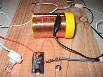
Homemade printed circuit board The receiver is made under the circuit of the original and has already been finalized in the field to prevent self-excitation. The board is installed on the chassis with hot glue. To shield the inductor L3, an aluminum shield connected to a common wire is used. The magnetic antenna in the first versions of the chassis was installed at the top of the receiver. But from time to time, metal objects and cell phones were placed on the receiver, which disrupted the operation of the device, so the magnetic antenna was placed in the basement of the chassis, simply gluing it to the panel. KPI with an air dielectric is installed with screws on the scale panel, the volume control is also fixed there. The output transformer is used ready from a tube tape recorder, I admit that any transformer from a Chinese power supply is suitable for replacement. The receiver does not have a power switch. Volume control is required. At night and on “fresh batteries”, the receiver starts to sound loud, but due to the primitive design of the ULF, distortion begins during playback, which is eliminated by lowering the volume. The scale of the receiver was made spontaneously. Appearance The scale was compiled using the VISIO program, with the subsequent transfer of the image into a negative form. The finished scale was printed on thick paper by a laser printer. The scale must be printed on thick paper; when temperatures and humidity fluctuate, office paper will go in waves and will not restore its previous appearance. The scale is completely glued to the panel. Copper winding wire is used as an arrow. In my version, this is a beautiful winding wire from a burned-out Chinese transformer. The arrow is fixed on the axis with glue. The tuning knobs are made from carbonated drink caps. The handle of the desired diameter is simply glued into the lid with hot glue.
Board with cells Container with batteries
As mentioned above, the "earth" power option did not go. As alternative sources, it was decided to use dead batteries of the “A” and “AA” formats. The farm constantly accumulates dead batteries from flashlights and various gadgets. Dead batteries with a voltage below one volt became power sources. The first version of the receiver worked for 8 months on one "A" battery from September to May. A container is glued on the rear wall especially for power supply from AA batteries. Low current consumption assumes that the receiver is powered by solar panels of garden lights, but so far this issue is irrelevant due to the abundance of AA format power sources. The organization of power supply with waste batteries served as the assignment of the name "Recycler-1".
Homemade radio loudspeaker
I do not urge you to use the loudspeaker shown in the photo. But it is this box from the distant 70s that gives the maximum volume from weak signals. Of course, other columns are also suitable, but the rule works here - the more the better.
Outcome
I would like to say that the assembled receiver, having a low sensitivity, is not affected by radio interference from TVs and switching power supplies, and the quality of sound reproduction from industrial AM receivers is different purity and saturation. During any power failures, the receiver remains the only source of listening to programs. Of course, the receiver circuit is primitive, there are circuits of better devices with economical power supply, but this do-it-yourself receiver works and copes with its “duties”. Spent batteries are regularly burned out. The scale of the receiver is made with humor and jokes - no one notices this for some reason!
Final video
The article will fully study the detector receiver, its main components and the possibilities for upgrading this simple device. For the normal functioning of this receiver, a careful selection of elements according to the parameters is required. But it is very demanding on the design of the antenna and grounding, since the receiver does not have a power source. It works exclusively due to the electromagnetic field created by the radio transmitter. This is both an advantage and a disadvantage of a radio receiver assembled according to such a scheme. It can work almost forever as long as radio stations are broadcasting. But its sensitivity is extremely low, it is able to receive only very powerful signals.
Antenna design
A special requirement is placed on the design of the antenna. It is she who performs the function of a power source in the detector radio. From this we can conclude that it is quite simple to use a detector receiver. But there are a number of shortcomings that cannot be eliminated. In particular, the output voltage is very low, even if the radio is tuned to the frequency of the signal transmitter. In other words, you will not collect a lot of potential from the antenna. But it should ensure the stable operation of the device. Several types of antennas are used for this purpose, but the most popular and simplest is the "long beam".
At a height of at least three meters, you need to hang a piece of wire. Its length must be at least ten meters. Moreover, it is desirable to use a copper wire in lacquer insulation (note: this one must subsequently be used in an inductor). The thickness of the wire is over one millimeter. As you understand, it will be hung in two places, and the edges must be insulated. Otherwise, all the energy will go into the ground. It is best to conduct insulation using ceramic elements. The drop wire is made from one of the edges of the antenna, securely soldered to the canvas at a distance of 30-50 cm from the end.
Grounding for detector radio

In this section, you can also talk a lot, because if the antenna is the “positive” power wire, then the ground is “negative”. And without it, a detector receiver, assembled with your own hands, simply will not work. Of course, in the absence of high-quality grounding, you can use water pipes (if you don’t have plastic ones), heating pipes, even a zero output in a socket. But be careful with the latter, it’s better to check where the phase is seven times, otherwise electric shock cannot be avoided. But the way to turn on the “zero” of the socket will allow to make a detector receiver with high sensitivity and selectivity, since the quality of the ground is very good.
A completely working grounding structure for such a receiver is a piece of pipe about a meter long, hammered into the ground. With the same success, you can use reinforcement (it will even be easier to work with it). Good results are shown by an iron plate dug to a depth of a couple of bayonets of a shovel. At the same time, the larger the area of \u200b\u200bthe metal surface of the plate, the better. In other words, you can use any metal object that is securely fixed in the ground. Please note that in hot weather, you need to pour water on the place where the ground pin is located. This will improve metal-to-ground contact. Another design suggests itself - casing metal pipes in wells can be used as grounding.
How to make an oscillatory circuit

Now about how to make a detector receiver with your own hands in a short time. When you have an antenna and ground, you can start manufacturing the device. First of all, you need to make an oscillatory circuit. This is an inductor and a capacitor connected in parallel. With the help of these elements, the receiver is tuned to resonance with the antenna. Please note that the capacitor must be variable. Can be used with both air dielectric and paper.
The coil is wound with the same wire that was used in the antenna. It is necessary to make at least one hundred turns on a mandrel with a diameter of 3-5 cm. In order to subsequently have a larger range of received frequencies, you make taps from each 25th turn. By a simple change number of turns, you achieve a frequency shift in the right direction. The winding should be carried out turn to turn, while the tension of the wire should be sufficient so that the detector receiver subsequently works normally. The coil must be wound with wire, which is firmly fixed on the mandrel. Its ends are securely fixed, if necessary, can be coated with a layer of varnish or epoxy. That's all, now you need to move on to the manufacture and modernization of the radio.
Device Assembly

Here are all the elements that make up the detector receiver circuit:
- Inductor.
- Variable capacitor (capacity 4-495 pF).
- Permanent capacitor (capacitance over 3000 pF). It is advisable to use those that are made of foil and paper. Ceramic will not work.
- Semiconductor diode type D9. Of course, today this is unlikely to be obtained, so you can replace it with any other. The main thing is that it should be high-frequency and based on a silicon crystal. For example, KD502 with any letter ending.
- For starters, high-impedance headphones. The Soviet industry produced TON-2, their winding resistance is 1600 ohms, they are ideal for use in a detector radio. Subsequently, a small bass amplifier will be made, so you can listen to the receiver through the speaker.
- And the means of switching - a clip of the "crocodile" type, sockets and plugs for them.
Perhaps this completes the collection of all the elements, so you can safely make a radio according to the scheme. It is simple and can be made without soldering.
What to do if there is no necessary diode?

The semiconductor diode acts as a detector, so it is problematic to replace it. But there are designs that can take on the role of a detector. And this is not about radio tubes or microcircuits. You can make a detector receiver from a blade and a pencil, they are placed instead of a diode. All other elements remain in place. You will also need a pin, you need to insert it into back pencil. In this case, the two elements must be rigidly connected. The pencil is set to the blade at an angle of 30-45 degrees.
The disadvantage of such a “detector” is that you often need to sharpen the end of the pencil. And it will not work with stupid. But this design is only for general development, but in case of an apocalypse, it will be much easier to use a diode. For lack of a suitable one, you can easily install a transistor. Only one p-n junction needs to be used in it. If you are reading this article, then most likely you know that there are p-n-p transistors And n-p-n type. From here you need to push off, apply a signal from the oscillatory circuit to the base, remove the detected signal from the collector. A replacement for the semiconductor diode has been found, now you can begin to improve the design of the radio.
Improved detector radio circuit

A small improvement is the introduction of a simple low-frequency signal amplifier into the circuit. For normal listening to radio stations through headphones, the energy generated by the antenna is not enough, so you need to apply the simplest amplifying stage circuit on a single transistor with a common emitter. To implement it, you need to acquire a KT315 type transistor, as well as several resistors and capacitors. Of course, the circuit of the detector receiver will become a little more complicated. What element is used to amplify in this case? We are talking about a transistor, a brief diagram of its connection is described below.
It is necessary to apply a low-frequency signal to the base (from the output of the radio receiver). A resistor is connected between the collector and the positive power wire. Its resistance should be selected experimentally, but it is worth starting from a value of about 10 kOhm. But the base of the transistor must be powered from minus and plus. Therefore, power is supplied from the plus through a resistor of about 200 kΩ with a resistance (also selected experimentally). A resistor of about 5 kΩ is connected between the base and the emitter. Headphones are connected to the negative power wire and to the collector of the transistor.
Ferromagnetic coil design

Instead of the bulky inductor described above, a smaller one can be used. True, it must be wound on a ferrite rod. You can find this in any old radio, even domestic, even imported. For this reason, it is necessary to mention how to make a detector receiver with a magnetic antenna (with a coil on a ferrite rod). The wire can be used much thinner, you don’t have to make taps from the turns, since you can change the inductance of the coil by moving the turns on the rod. The wire diameter is 0.1-0.15 mm, the number of turns is about a hundred. If the receiver is made to listen to a fixed frequency, then the winding can be fixed on the rod with varnish.
Assembling an additional bass amplifier

Above, the circuit of a simple low-frequency amplifier for a radio was considered, but with its help you can listen to stations only on headphones. But if you need a loud-speaking detector receiver, you will have to use modern elements. Of course, you can easily install a 3.5 mm jack at the radio output, connect the speaker plug for your computer to it. This is perhaps the best way out of the situation. But if there are no speakers, then it is easier to make a small amplifier on a microcircuit. Reinforcing assemblies TDA2003, 2005 are perfect. It is only worth choosing from those with unipolar power supply.

They work great with a four- and eight-ohm load, allow you to provide a wide range of reproducible frequencies, and most importantly, the receiver will have enough volume. Of course, they perceive at their entrance even the most weak signals. But there is one drawback - they heat up, so you need to use an additional radiator for cooling. It is worth noting that it is much easier to make the simplest detector receiver with a low-frequency amplifier on a microcircuit, since such designs turn out to be much more efficient than ULF on lamps or transistors. The former need to power the anodes (and this is at least 150 volts), while the latter are simply difficult to manufacture. And the quality is not always good.
Increasing the sensitivity of the receiver

But here's how to improve the quality of the signal itself that the radio receives? And to be more precise, how to increase the number of radio stations that you can listen to? A little time and you will make a detector receiver with high sensitivity and selectivity. To do this, you need to install an additional high-frequency amplifier. With its help, an increase in the amplitude of the signal is carried out without losing its shape. It can be made by analogy with ULF on one transistor. Moreover, field-effect transistors turn out to be more effective in such designs. In general, if bipolar is used, the circuit is very similar to a low frequency amplifier.
Installing the power supply

When you get tired of changing batteries, you will realize that you need a power source from the mains. If available solar battery, then it can be used to recharge batteries, but if there is none, then you will have to take a ready-made power supply from some household appliance. The detector receiver can be powered, for example, by taking a block from antenna amplifier TV, from a DSL modem. Just do not use chargers from phones, as they are pulsed. If everything is really bad, then 5 Volt power can be easily taken from the USB connector of a laptop or computer (two extreme pins in the plug).
Conclusion

After reading this article, you will be able to make the simplest detector radio receiver yourself. Moreover, the manufacturing work can be carried out literally on the knee. The design does not require scarce parts, and improvement can be carried out using any components.
Comments (29):
#1 Filyuk Victor October 31 2014
Hello. As far as I understand, the receiving frequency of the device lies within the VHF "our range". And how do you need to change the coil data so that you can cover the entire FM range ??? .Thank you.
#2 root October 31 2014
For the FM band, you will need to reduce the number of turns of the inductor L1. The value of the number of turns is selected experimentally, and the expansion / decrease in the distance between the turns of the coil affects the operating frequency of the L1C2 circuit.
For the range 65.8-73 (MHz), the transistor must be P416 with the letter B or another higher frequency.
For the 88-108 (MHz) range, a higher-frequency transistor is needed than the P416B. For the new range, you can try to use GT308B-G (threshold 120 MHz), as well as KT361 with any letter (threshold 250 MHz) or KT3107 (threshold 200 MHz).
#3 V. Borovkov December 01 2014
Hello! I'm somehow not sure that even the regeneration noise will be heard in headphones (in phones), a useful signal, the noise is very small. You yourself made such a receiver and did it work for you ?? At least I'm not sure, but I wonder if it's possible that it will work as it is written ...
P416 p-n-p, and KT603 n-p-n .. be careful, let's give analogs to beginners .. or you need to specify kt603 to change the polarity .. *** I collected for the sake of interest .. a couple of stations near Kyiv work ...
#5 root Dec 25 2014
March, thanks for the comment. The mention of kt603 was removed from the article so as not to confuse newcomers. Now there are a lot of high-frequency transistors that can replace the old germanium P416.
I don’t think that P416 is already gone, there are still many from P401 to 416 * 422, old GT308, etc. And germanium generally works better. (who needs to send ..)
#7 root Dec 26 2014
Yes, there are still such transistors at flea markets, I recently bought several GT308 for a penny - the sellers were surprised that someone still needed these rarities))
Germanium transistors do have some advantages over silicon ones. In the article Tube-transistor ULF for headphones there is a plate where they are compared physical properties silicon and germanium.
I will give briefly advantages of germanium over silicon:
- density is more than 2 times higher;
- the mobility of electrons and holes is about 3 times higher;
- the lifetime of an electron is 2 times higher.
For radio receiving and sound reproducing equipment, germanium can prove to be very interesting! In addition, very economical designs can be assembled on germanium transistors, for example:
- Economical radio receivers with low-voltage power supply (0.3-0.7V) from an earth battery;
Therefore, in this design, a VHF receiver on one transistor will also be a plus use of germanium transistor.
#8 Clide January 07 2015
Hello, I am a beginner in this business. Please write to the account of capacitors C1 and C3 what units of measurement are there, and how important is the capacitance indicated in the diagram
#9 root January 08 2015
Capacitor C1 \u003d 12 pF (picoFarad) - here you can allow some deviation, most likely that the capacitance of the capacitor within 10-15 pF will not affect the operation.
Capacitor C3 \u003d 36 pF (picoFarad) - in this circuit, a minimum deviation is desirable, you can try 30-40 pF.
Also, any capacitance, if there is no exact value available, can be added up from several capacitors by connecting them in parallel - while the capacitance of all capacitors is summed up.
Example: you need a 36pF capacitor - we connect two 10pF and 25pF capacitors in parallel, we get 35pF, which is quite suitable for installation in a circuit.
#10 Clide January 16 2015
Hello again. Thank you very much for your help, thanks to you I have assembled my first receiver!
Ps: Catches fm light :)
The P416B transistor can be replaced with a GT308A or other high-frequency N-P-N structure. Well, here it is again..not N-P-N a P-N-P.
#12 root January 16 2015
When I was correcting the article, I made a mistake due to inattention. Why I got so attached to N-P-N, it affects to see close communication with the circuits on KT315)) Corrected! Thank you March.
Clide, that's great! If it doesn’t make it difficult, write down which parts were changed and which headphones were used.
#13 Clide January 16 2015
Transistor p422 c1 and c3 30pf each C2 - KPI with an air gap, L1 11mm (by the way, this is clearly AA battery) 10 turns with a cross section of 0.4mm. The headphone output from the player through a 500-1000 Ohm resistor, also in parallel with the 500 Ohm resistor through a capacitor, put the leads on the ULF amplifier
Since the transistor is rather weak, I'm afraid to burn it with my lack of theoretical knowledge
#14 Clide January 28 2015
I need help again, in general, I added one amplifying stage on a composite transistor, the receiver became louder, everything seems to be as it should, but when I increased the power supply from 2.5V to 5V, it started to work the other way around, namely, to create very strong interference, it completely jams TV, while the function of the receiver is almost completely lost. Please let me know what could be causing this.
Here is a complete diagram of this enemy of neighbors.
And yes, I still burned the old transistor, by accident)
#15 root January 29 2015
Completely working solution. The circuit becomes a transmitter because you gave a lot of current to the KT603 transistor - try instead of a 100 Ohm resistor to put a variable resistor of 2-5 kOhm and experiment, also try to reduce the capacitance of the input capacitor by 10 uF to 0.47 - 1 uF and less. The values to change are underlined in red on your diagram.
In the article Scheme of a VHF (FM) super-regenerator on two transistors there is a similar solution, you can try to connect the amplifier in the same way only with a composite transistor.
Here are some diagrams and articles from which you can get ideas and knowledge on simple homemade transistorized FM radios:
- A simple regenerative VHF-FM receiver with four transistors
- Super-generative transistorized VHF receivers with low voltage supply (1.5V)
- Transistor VHF (FM) receivers with stereo ring decoder
#16 Clide January 29 2015
Yes, indeed, the 100 ohm resistor was to blame for the interference. temporarily set a variable, and set the capacitor to 1 microfarad. I got rid of the interference, but unfortunately, for some reason, it is precisely from 5 volts that the receiver still refuses to work normally, namely, the sound is very distorted, and excessive sensitivity appears, which you have to turn by a micron, and you yourself cannot move. In general, I think that this is some kind of transistor feature, I’ll look for another one, I’ll try, if it doesn’t work out, I’ll reduce the voltage and that’s all, or I’ll assemble it according to a different scheme
#17 root January 29 2015
Connect a 5V power supply and try to put a 200-300 kΩ variable resistor instead of R1, turning the knob to see how the receiver operation changes.
In the amplifier circuit, replace the 280 Ohm resistor with 2-3 kOhm, and select the operating mode with the resistor that you have in the 52 kOhm circuit.
Try to put transistor GT313 or GT311. They have a cutoff frequency of about 400 MHz. First p-n-p structures as well as P416, P422. Second n-p-n, the polarity of the power supply is reversed. GT313 can be found in SKM or VHF units of Soviet radio receivers such as Okaen etc.
#19 Sergey October 10 2018
What resistance p1 just I do not see?
#20 root October 10 2018
Sergey, the resistance of the resistor R1 is 330 kOhm (330,000 Ohm).
#21 Alexander the Compromiser October 11 2018
I have a question, a suggestion and a remark: firstly, why does the resistor R1 have a relatively large power of 0.5 W instead of the common power of 0.125 W (see the Zakharov-Sapozhnikov diagram)? - In this regard, the coil L1 can be wound directly on the resistor R1 (but you need to choose the number of its turns). - This is secondly, and thirdly, a remark: according to the ESKD rules, the power key is drawn in the opposite direction, i.e. not from the power supply, but from the load.
#22 root October 12 2018
The diagram has been redrawn. Resistor R1 is low-power, you can set it to 0.125W or any other power. Coil L1 - frameless.
#23 Kostya May 06 2019
Hello. I am doing a coursework according to your scheme. Help with choosing a speaker. I connected the speaker, but it does not even hiss. More details if possible!
#24 root May 06 2019
Hello. This circuit cannot be connected directly to 4-8 ohm speakers, as well as 16-50 ohm headphones. If you do this, then the transistor will fail. The circuit is designed to connect phones with a resistance of 1600-2200 ohms. To use these speakers and headphones, you need to connect a matching transformer.

A miniature matching transformer can be removed from an old radio or made by yourself.
![]()
You need to connect it to the circuit with winding I with a resistance of more than 1 kOhm, and to the speaker or headphones - with winding II, with a resistance of several tens of Ohms.
#25 Alexander the Compromiser May 07 2019
Will the transformer from the subscriber loudspeaker fit?
#26 root May 08 2019
Alexander, it will do, but the playback volume will be lower than using a transformer removed from a portable radio.
#27 Alexander the Compromiser May 08 2019
Is it possible to use the mode D of the output transistor in this case and increase the voltage? - What sampling rate should be chosen in this case? - Yes, obviously fd>=2fv, but why take fv equal?
#28 Seawar May 08 2019
This is an analog circuit. Output transistor at the same time є і input - і local oscillator, і zmіshuvachem, і ULF, і ULF. You can (optimally) connect an additional ULF, and choose the next mode - right relish.
#29 Nicholas September 16 2019
I decided to make such a receiver, all the details are there, BUT I did not find a 9 volt power source. Therefore, I decided to assemble a transformer for 9 volts from 220 volts (I'm still a beginner). And the circuit worked for me from such 9 volts, but I have absolute pitch and the radio works, but the sound on the “sol” note of the lower octave (station + lower note) is constantly heard in the phone. How to fix it? If I insert a normal krone battery, will this sound stop?
With just one chip, you will need to build a simple and complete FM receiver that is capable of receiving radio stations in the 75-120 MHz range. The FM receiver contains a minimum of parts, and its setup, after assembly, is reduced to a minimum. It also has good sensitivity for receiving VHF FM radio stations.
All this thanks to the Philips TDA7000 chip, which can be bought without problems on our favorite Ali Express -.
Receiver circuit
Here is the receiver schematic. Two more microcircuits are added to it, so that in the end we get a completely finished device. Let's start looking at the diagram from right to left. On the LM386 running chip, a low-frequency amplifier for a small dynamic head, which has already become a classic, is assembled. Here, I think, everything is clear. The variable resistor controls the volume of the receiver. Further, a stabilizer 7805 is added above, which converts and stabilizes the supply voltage up to 5 V. Which is needed to power the receiver's microcircuit. And finally, the receiver itself is assembled on the TDA7000. Both coils contain 4.5 turns of wire PEV-2 0.5 with a winding diameter of 5 mm. The second coil is wound on a frame with a ferrite trimmer. The receiver is tuned to the frequency with a variable resistor. The voltage from which it goes to the varicap, which in turn changes its capacitance.If desired, from the varicap and electronic control you can refuse. And the frequency can be tuned either with a tuning core or a variable capacitor.
FM receiver board
I drew the circuit board for the receiver in such a way as not to drill holes in it, but to solder everything from the top, as with SMD components.Placement of elements on the board

Used the classic LUT technology for the production of the board.


I printed it out, warmed it up with an iron, etched it and washed off the toner.


Soldered all the elements.

Receiver setup
After turning it on, if everything is assembled correctly, you should hear a hiss in the dynamic head. This means that everything is working fine so far. The whole setting comes down to setting the contour and selecting a range for reception. I tune by rotating the core of the coil. As the reception range is configured, the channels in it can be searched for by a variable resistor.Conclusion
The microcircuit has good sensitivity, and on a half-meter piece of wire, instead of an antenna, it is caught a large number of radio stations. The sound is clear, without distortion. Such a scheme can be applied in a simple radio station, instead of a receiver on a supergenerative detector.The simplest radio receivers are unsuitable for catching the FM band, frequency modulation. The townsfolk claim that this is where the name comes from. From the English letter FM we interpret: frequency modulation. It is important for readers to understand a clearly expressed meaning: the simplest radio receiver, assembled from rubbish with your own hands, will not accept FM. The question arises whether: cellular telephone catches the broadcast. This capability is built into the electronics. Far from civilization, people still want to catch broadcasts in the good old way - they almost said with dental crowns - to construct efficient devices for listening to their favorite programs. For free…
Detector elementary radio receiver: the basics
The story touched on dental fillings for a reason. Steel (metal) is capable of converting ethereal waves into current, copying the simplest radio receiver, the jaw begins to vibrate, the bones of the ear detect the signal encrypted on the carrier. With amplitude modulation, a high frequency repeats the speaker's voice, music, sound in a big way. The useful signal contains a certain spectrum, which is difficult for a non-professional to understand, it is important that when the components are added, a certain law of time is obtained, following which the speaker of a simple radio receiver reproduces the broadcast. On dips, the jawbone freezes, silence reigns, the ear hears peaks. The simplest radio receiver, God forbid, of course, get hold of it.
The reverse piezoelectric effect changes, according to the law of the electromagnetic wave, the geometric dimensions of the bones. Promising direction: human-radio receiver.
The Soviet Union was famous for launching a space rocket, ahead of the rest, for scientific research. Union times encouraged degrees. The luminaries have brought a lot of benefits here - the design of radios - they earn decent money over the hill. Movies promoted the smart, not wealthy, it is not surprising that magazines are full of various developments. A series of modern lessons on creating the simplest radios, available on YouTube, is based on magazines published in 1970. Let's be careful not to deviate from traditions, we will describe our own vision of the situation in the field of amateur radio.
The concept of a personal electronic computer was developed by Soviet engineers. The party leadership recognized the idea as unpromising. Forces are given to the construction of gigantic computing centers. It is unnecessary for a worker to master a personal computer at home. Funny? Today you will meet more amusing situations. Then they complain - America is shrouded in glory, printing dollars. AMD, Intel - have you heard? Made in USA.
Everyone will make the simplest radio receiver with their own hands. Antenna is not needed, there is a good stable broadcast signal. The diode is soldered to the outputs of high-impedance headphones (discard computer ones), it remains to ground one end. In fairness, let's say the trick will work with the good old Soviet-issue D2, the taps are so massive that they will serve as an antenna. We get the earth in the simplest radio receiver by leaning one leg of the radio element against the heating battery, stripped of paint. Otherwise, the decorative layer, being a dielectric of the capacitor formed by the leg and the metal of the battery, will change the nature of the work. Try.
The authors of the video noticed: there seems to be a signal, it is represented by an unimaginable mishmash of rustles, meaningful sounds. The simplest radio receiver lacks selectivity. Anyone can understand, understand the term. When we set up the receiver, we catch the desired wave. Remember, we discussed the spectrum. Aether contains a bunch of waves at the same time, catch the right one by narrowing the search range. There is selectivity in the simplest radio receiver. In practice, it is implemented by an oscillatory circuit. Known from physics lessons, formed by two elements:
- Capacitor (capacity).
- Inductor.
Let's take a moment to study the details, the elements are equipped with reactance. Due to this, waves of different frequencies have unequal attenuation when passing by. However, there is some resonance. For a capacitor, the reactance on the diagram is directed in one direction, for an inductance - in the other, and the frequency dependence is derived. Both impedances are subtracted. At a certain frequency, the components equalize, the reactance of the circuit drops to zero. There is a resonance. Pass the selected frequency, adjoining harmonics.

The course of physics shows the process of choosing the bandwidth of the resonant circuit. Determined by the attenuation level (3 dB below maximum). Here are the calculations of the theory, guided by which a person can assemble the simplest radio receiver with his own hands. Parallel to the first diode, a second one is added, connected towards. Soldered in series to the headphones. The antenna is separated from the structure by a 100 pF capacitor. Here we note: the diodes are endowed with a capacitance of the p-n junction, the minds, apparently, have calculated the reception conditions, which capacitor is included in the simplest radio receiver, endowed with selectivity.
We believe that we will slightly deviate from the truth, saying: the range will affect the HF or MW regions. Multiple channels will be received. The simplest radio receiver is a purely passive design, devoid of an energy source; great achievements should not be expected.
A few words why we discussed remote nooks and crannies where radio amateurs are eager for experiments. In nature, physicists have noticed the phenomena of refraction, diffraction, both allow radio waves to deviate from a direct course. Let's call the first one the avoidance of obstacles, the horizon moves away, yielding to broadcasting, the second one - refraction by the atmosphere.
LW, MW and HF are caught at a considerable distance, the signal will be weak. Therefore, the simplest radio receiver discussed above is the touchstone.
The simplest radio receiver with amplification
In the considered design of the simplest radio receiver, low-impedance headphones cannot be used, the load resistance directly determines the level of transmitted power. Let's first improve the performance using a resonant circuit, then supplement the simplest radio with a battery by creating a low frequency amplifier:

- The selective circuit consists of a capacitor, inductance. The magazine recommends that a variable capacitor of the tuning range of 25 - 150 pF be included in the simplest radio receiver, the inductance must be made according to the instructions. A ferromagnetic rod with a diameter of 8 mm is wrapped evenly with 120 turns, capturing 5 cm of the core. A copper wire covered with varnish insulation with a diameter of 0.25 - 0.3 mm is suitable. They gave readers the address of the resource, where you can calculate the inductance by entering numbers. The audience can independently find, using Yandex, calculate the number of mH of inductance. The formulas for calculating the resonant frequency are also well known, therefore, it is possible, remaining at the screen, to imagine the tuning channel of a simple radio receiver. The tutorial video suggests making a variable coil. It is necessary to push the core inside the frame with wound coils of wire. The position of the ferrite determines the inductance. Calculate the range, using the help of the program, YouTube craftsmen offer, winding the coil, draw conclusions every 50 turns. Since there are about 8 taps, we conclude: the total number of revolutions exceeds 400. Change the inductance stepwise, fine-tune with the core. Add to this: the antenna for the radio is decoupled from the rest of the circuit with a 51 pF capacitor.
- The second point you need to know is that the bipolar transistor also has p-n junctions, and even two. Here the collector is just appropriate to use instead of a diode. As for the emitter junction, it is grounded. Then power is supplied to the collector directly through the headphones direct current. The operating point is not selectable, so the result is somewhat unexpected, it will take patience until the radio device is perfected. The battery also plays a big part in your choice. We consider the headphone resistance to be collector, which sets the slope of the output characteristic of the transistor. But these are subtleties, for example, the resonant circuit will also have to be rebuilt. Even with a simple replacement of the diode, not like the introduction of a transistor. That is why it is recommended to conduct experiments gradually. And the simplest radio receiver without amplification will not work at all for many.
And how to make a radio receiver that would allow the use of simple headphones. Connect through a transformer, like the one at the subscriber point. A tube radio differs from a semiconductor in that it requires power to operate anyway (filament).
Vacuum devices go into mode for a long time. Semiconductors are ready to receive immediately. Don't forget: germanium does not tolerate temperatures above 80 degrees Celsius. If necessary, provide cooling of the structure. At first, this is necessary until you select the size of the radiators. Use fans from personal computer, CPU coolers.


