Nowadays, radio waves are no longer unknown. Radio amateurs began to appear everywhere. In their work or hobby, such a device as an antenna analyzer is directly involved. What it is, what types of it exist and how it works will be discussed later in this article.
RigExpert analyzer
There are many different models, but this article will only cover a few of them. One of the multifunctional devices is RigExpert AA 600. The purpose of this device is to configure, check and repair antennas, as well as antenna-feeder paths. The key metrics of this instrument are SWR - standing wave ratio - and impedance. Both of these characteristics are displayed graphically on this device.
In addition, there are such additional functions as graph memory, connection to a computer, as well as easy-to-use measurement modes. All this makes the RigExpert AA 600 quite suitable for use by both professionals and amateurs. Also, this device has two more distinctive measurement modes that make it stand out from the crowd, they are MultiSWR ™ and SWR2Air ™. In order to make it much easier to find any faults on the cable lines, this antenna analyzer has a built-in mode for analyzing discontinuities along the transmission line.
Specifications
The RigExpert antenna tuner has the following technical parameters:
- The frequency range of the device is from 0.1 to 600 MHz.
- The resolution or frequency of frequency input for this device is 1 kHz.
- It is possible to carry out measurements with this device in systems with resistance of 25, 50, 75, 100 Ohm.
- The measuring range of the standing wave ratio (SWR) in numerical values is from 1 to 100, and in the graphical mode - from 1 to 10.
- SWR is displayed as a filled bar or as a digital indication.
- There is the possibility of optional calibration in the graphical SWR mode, as well as on R, X and Smith pie charts.
Power for this model can be supplied from the following sources:
- Alkaline batteries in the amount of 3 pieces with a voltage of 1.5 V. The standard size for these batteries is AA.
- Nickel-metal hydride batteries also in the amount of 3 pieces, each of which has a voltage of 1.2 V and a capacity of 1800 to 3000 mAh.
The operating time of this model is a maximum of 3 hours in continuous measurement mode, or two days if the device is in "standby" mode. These times are suitable for freshly charged batteries in the device.
Precautionary measures
There are several rules to follow when using this antenna analyzer.
- It is strictly forbidden to make any measurements or simply connect the device to an antenna during a thunderstorm. A lightning strike, as well as the static voltage that accumulates in the antenna, is fatal to humans.
- Do not leave the device connected to the antenna after work has been completed. A thunderstorm or other nearby transmitter can damage it.
- It is forbidden to send signals with a high frequency to the input of the device, and also to turn on the transmitter if there is already another working radio wave transmitter nearby.
- The cable must be grounded before connection. This is divided in order to avoid electric shock from the static discharge of electricity present in the cable.
- It is not recommended to leave the antenna tuning device switched on if all the necessary measurements have been taken. This will interfere with nearby transmitters.

Model overview SARK
The device of this company appeared quite a long time ago and at one time was the best in such a ratio as price-quality. But today this device is quite successfully operated and in demand.
Model SARK 110 is a vector complex impedance meter. The measurement is carried out in the range from 0.1 to 230 MHz. In addition, this device also shows VSWR and R-L-C in serial as well as parallel equivalent. In addition to these indicators, the device also shows the quality factor, phase, reflection coefficient of the connected load. In addition, it can measure cable length and distance to the point where the discontinuity is located.
The data is displayed on a 3-inch screen as conventional Voltaire-Smith pie charts or as conventional numbers. If the screen seems too small, it is possible to connect the device to a computer via a USB cable and display data on its monitor.

Purpose of the SARK model
It should be said that this antenna analyzer is a very serious device that has a wide range of various functions. In order to describe all of them, it will take quite a lot of time, and therefore only the main ones will be given.
The device has a synthesizer to perform the following functions:
- Direct digital synthesis with 1 Hz accuracy.
- Sinusoidal output signal.
- The operating frequency range is from 0.1 to 230 MHz.
This model can also measure the following parameters:
- Complex impedance in series and parallel equivalent, in rectangular or polar coordinates.
- Reflectance in the same rectangular or parallel equivalents.
- VSWR, return loss, and percentage of reflected power.
- The last things this analyzer can measure are Q-factor, inductance and equivalent capacitance.

Features of work
This antenna analyzer has some common features that apply to all the jobs that this model can do.
- Provides presets for all amateur bands that fall within the band of the fixture.
- Has an adjustable reference impedance.
- It is possible to save all the collected data in the analyzer's memory, and then call them from there if necessary.
- Provides presets for most of the popular cables used for connection.
- It is possible to add or subtract the transmission factor.
- white or black.
- It is possible to manually adjust the thickness of the graphs.
In addition to performing analysis, this device can also perform the following types of work:
- Construction of rectangular graphs.
- Building a Smith pie chart.
- Single frequency mode.
- Measuring the cable.
- Field mode.
- Multi-band mode.
- High frequency generator.
It is also worth adding that the battery life of this device is approximately 2.5 hours.
Analyzer AA-330M
The purpose of this device is to study the characteristics of the HF antenna-feeder device. The device is portable, but it is located in a housing made of impact-resistant plastic. The model has a wide range of features that will suit both professionals and amateurs. The AA-330M antenna analyzer is equipped with an interface that allows communication with a computer, and also has software, which further expands the possibilities for studying the characteristics of various antennas. This model can work in automatic mode, in which it will scan the selected frequency range. It can also work in manual mode, in which it has a convenient step encoder, which, in turn, has a button function, so that you can quickly and more conveniently select parameters.

Device capabilities
The model has a wide range of different capabilities. During measurements, the device displays parameters such as VSWR, frequency, active and reactive components of resistance, as well as the sign of reactivity. At the same time, all graphs that can be saved at the moment will be displayed on the computer screen. This function is very convenient, since these graphs can be called up later in order to analyze simultaneously with new measurements from other antennas. Thus, it is possible to compare the performance of the new antennas with the old ones that were dismantled a long time ago. Another very convenient function is the automatic finding of the resonant frequency by the device during scanning of the selected range. This saves a lot of time and also reduces the effort required to tune the antenna. By turning the knob of the knob, it is possible to scan all frequencies in steps of 1, 10, 100, 250 KHz.
Functions of the AA-330M
The AA-330M model has the ability to work as a sinusoidal current generator, which generates a signal level at the output of 1.4 V. There is also the possibility of restructuring the step in 1, 10, 100, 250 KHz. Another of the device's functions is the ability to work with two different feeder lines - 50 and 75 Ohm. For this, the device has two different measuring bridges. The device is equipped with a function to turn off the backlight on the screen. This action is applied when using the device in "field" conditions and makes it possible to increase the analyzer's operating time by about 30%. There is also another function that allows you to write all the data obtained after scanning to the volatile memory of the device. There is a possibility of the subsequent display of the recorded data on the monitor screen, and the saving of graphs occurs when the device is turned off. The accuracy and reliability of this instrument have been verified in numerous experiments with R-SQUAD antennas.

Antenna feeder system
This system is designed to perform several functions.
- The first function of this system is the reception of interrogation signals, as well as the transmission of response signals in the sector in which the localizer is operating.
- The second is to ensure the joint operation of the receiving and transmitting devices on a common antenna. It also provides switching of work to the backup set in the event that the main worker breaks down for any reason.

It is also important to note that the antenna-feeder system consists of two components - an antenna system and a feeder path. In turn, the first of the two indicated elements includes eight different emitters, as well as one power divider that distributes it in eight different directions. And the feeder system includes components such as four directional couplers as well as two load-absorbing coaxial interconnect cables.
VSWR value
Nowadays, SWR meters are quite common and widely used. The value of these devices is great, moreover, the measurement of SWR, that is, the standing wave ratio, is widely used in antenna analyzers. However, despite the significant role of this equipment, few people reliably know what is still measured by such a SWR meter separately or built into the analyzer. It is well known that the standing wave ratio in a feeder is determined by two parameters. These include the input impedance of the antenna and the characteristic impedance of the feeder. It is also important to note that in the practical part, most often the measurement of these indicators must be carried out at a short distance from the antenna itself. Most often, this place is the transceiver.
How to set up TV
In order to set up MTS TV, there are two ways. One of them is pretty simple. It consists in purchasing the recommended set with a multimedia set-top box. The advantage of this method is that in such a set, all channels will already be configured. However, when using the CAM-module "MTS TV" Verimatrix, you will have to tune all the channels yourself. In order to do this, you can use the lists of transponders common on the Internet, as well as the frequency ranges that are attached to them. You can also use the antenna analyzers described above to find the required frequencies and tune them.
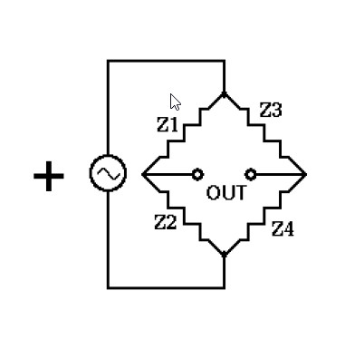
Antenna analyzer is a very useful tool Many radio amateurs would like to have a "proprietary" antenna analyzer like the MJF259, or similar. But such devices are too expensive ... However, I am sure that every radio amateur has a purchased or home-made HF generator and frequency counter. Using these two instruments and a differential bridge, a system can be obtained that can in many cases function as an antenna analyzer.The circuit shown in the figure was used to tune the HF antennas, from 1.6 to 30 MHz. We need an RF generator operating in this range. A frequency meter is needed to accurately determine this frequency. However, a frequency counter is not required if the MHF has a sufficiently clear and intelligible scale. The signal from the generator is fed to connector X1. Resistor R1 regulates the level (you can not set R1, but use the level regulator available at the generator).
The analyzed antenna is connected to the X2 connector. RF voltage is applied to the primary winding. The HF voltage on the secondary windings of the transformer is fed to a meter consisting of a P1 microammeter and a detector based on germanium diodes VD1 and VD2. The diodes must be germanium in order to ensure the highest sensitivity of the meter when indicating the minimum readings (balance).
The balance of the bridge is achieved by adjusting the resistor R3 and the variable capacitor C5. These parts must be supplied with scales indicating resistances and capacities corresponding to the angles of rotation of the handles. The balance is achieved in the case of equality of active and reactive resistances in both arms, Then, having achieved balance, you need to read the values of resistance R3 and capacitance C5. and then calculate the reactance C5 based on the given frequency. Thus, it will be possible to determine the active (R3) and reactive (C5) components of the analyzed antenna impedance.
Pay attention to the capacitance C3, which is 100 pF, that is, half of the maximum capacitance C5. If, during measurements, it turns out that the capacitance C5 in the balance is more than 100 pF, then this indicates the capacitive nature of the antenna reactance, but the value of C5, set less than 100 pF, on the contrary, indicates the inductive nature of the reactance in the antenna.
Transformer T1 is wound on a 600NN ferrite ring with a diameter of 10 mm. The windings are the same, they are made with three times folded winding wire of the type PEV with a diameter of 0.35. Eight turns evenly spaced around the ring. The beginnings of the windings are marked with dots in the diagram.
The circuit requires adjustment and calibration. The variable resistor R3 and the capacitor C5 must, as already mentioned, be equipped with scales with the values of resistance and capacitance, respectively (an ohmmeter and a capacitance meter are required).
Next, we connect the antenna equivalent to X2. - 50 ohm resistance, not inductive. On the U1 we send a signal of 15 MHz. Set the C5 knob to the 100pF position. We increase the voltage from the generator (resistor R1 or generator regulator) to the maximum reading of P1. Then, turning the knob R3, we look for a place with a deep dip in the readings of the device. Further, we make the readings of the device even smaller by adjusting the capacitor C5. On the C5 scale we make an additional mark, designated "0". This is the point where there is no reactive component in the load. The gap from the zero point to the maximum value of the C5 capacitance should be selected with a sector and marked as "Capacitive reactivity", and the gap from the same zero point to the minimum capacitance C5 should be selected with another sector and marked as "Inductive component of reactivity".

When tuning antenna-feeder systems, it is important to correctly measure the standing wave ratio (SWR). This parameter in an amateur environment is usually measured with a SWR meter at a fixed frequency, and the frequency response of the antenna is plotted through a series of successive measurements. For a single-band antenna, this classical method is quite applicable.
But in order to tune a multi-band HF antenna in this way, in which a change in the size of one structural element affects its parameters to varying degrees on several ranges, it will take a lot of effort and time.
Here you need an expensive or (semi) professional antenna analyzer, which will display a graph of the SWR value, as well as the active and reactive resistance of the antenna, depending on the frequency, on the display or screen. Convenient and intuitive.


Or even such a professional one, the price of which reaches $ 40,000.

And now the question arises - to buy a rather expensive or branded antenna analyzer or to do it yourself. Considering that this device is needed no more than once or twice a year. And the rest of the time it will be stored on the "top shelf". Unless, of course, you do not install and configure professionally. Laugh Or do it yourself (order) homemade, not expensive, and available components.
Antenna analyzer should be as simple as possible, its setup and calibration should be available at home without using any reference instruments. It should provide a panoramic measurement of SWR, with the display of graphs on the computer screen and (or) its own display in the frequency range of 1-30 MHz.
All analyzers, whether home-made or professional, use almost the same algorithm, the formula for calculating values is a measuring bridge. The only difference lies in the offered service, comfortable work, software that they use.

As a controller, you can use a ready-made Arduino Nano board, plus add a standard frequency synthesizer module to the AD9850.

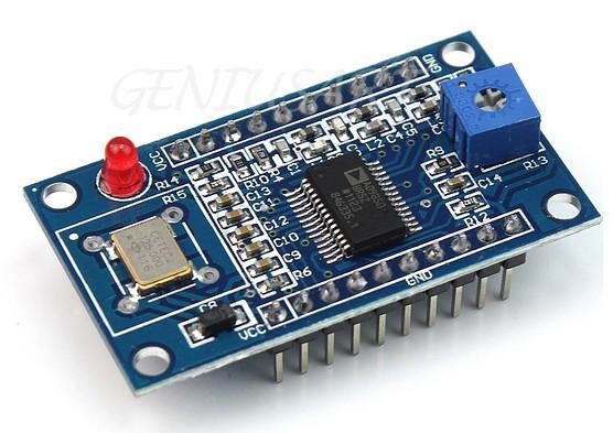
You just have to connect these two modules and add a board with several parts of the measuring bridge according to the proposed scheme.

As a "visual aid", by which you can periodically admire your antennas, a computer, a laptop with a simple, small program installed is used. The device (hardware) is controlled by a standard cable via a USB port.


- a very useful device Many radio amateurs would like to have a "proprietary" antenna analyzer like the MJF259, or similar. But such devices are too expensive ... However, I am sure that every radio amateur has a purchased or home-made HF generator and frequency counter. Using these two instruments and a differential bridge, a system can be obtained that can in many cases function as an antenna analyzer.
The circuit shown in the figure was used to tune the HF antennas, from 1.6 to 30 MHz. We need an RF generator operating in this range. A frequency meter is needed to accurately determine this frequency. However, a frequency counter is not required if the MHF has a sufficiently clear and intelligible scale. The signal from the generator is fed to connector X1. Resistor R1 regulates the level (you can not set R1, but use the level regulator available at the generator).
The analyzed antenna is connected to the X2 connector. RF voltage is applied to the primary winding. The HF voltage on the secondary windings of the transformer is fed to a meter consisting of a P1 microammeter and a detector based on germanium diodes VD1 and VD2. The diodes must be germanium in order to ensure the highest sensitivity of the meter when indicating the minimum readings (balance).
The balance of the bridge is achieved by adjusting the resistor R3 and the variable capacitor C5. These parts must be supplied with scales indicating resistances and capacities corresponding to the angles of rotation of the handles. The balance is achieved in the case of equality of active and reactive resistances in both arms, Then, having achieved balance, you need to read the values of resistance R3 and capacitance C5. and then calculate the reactance C5 based on the given frequency. Thus, it will be possible to determine the active (R3) and reactive (C5) components of the resistance analyzed antennas.
Pay attention to the capacitance C3, which is 100 pF, that is, half of the maximum capacitance C5. If during measurements it turns out that the capacitance C5 in the balance is more than 100 pF, then this indicates the capacitive nature of the antenna reactance, but the value of C5, set less than 100 pF, on the contrary, indicates the inductive nature of the reactive antenna impedance.
Transformer T1 is wound on a 600NN ferrite ring with a diameter of 10 mm. The windings are the same, they are made with three times folded winding wire of the type PEV with a diameter of 0.35. Eight turns evenly spaced around the ring. The beginnings of the windings are marked with dots in the diagram.
The circuit requires adjustment and calibration. The variable resistor R3 and the capacitor C5 must, as already mentioned, be equipped with scales with the values of resistance and capacitance, respectively (an ohmmeter and a capacitance meter are required).
Next, we connect to X2 antenna equivalent... - 50 ohm resistance, not inductive. On the U1 we send a signal of 15 MHz. Set the C5 knob to the 100pF position. We increase the voltage from the generator (resistor R1 or generator regulator) to the maximum reading of P1. Then, turning the knob R3, we look for a place with a deep dip in the readings of the device. Further, we make the readings of the device even smaller by adjusting the capacitor C5. On the C5 scale we make an additional mark, designated "0". This is the point where there is no reactive component in the load. The gap from the zero point to the maximum value of the capacitance C5 should be selected with a sector and marked as "Capacitive reactivity", and the gap from the same zero point to the minimum capacitance C5 should be selected with another sector and marked as "Inductive component of reactivity" Related materials: