Digital communication:
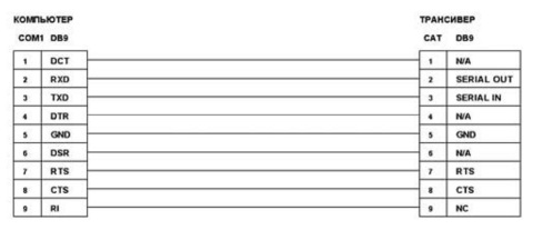
The transceiver was tested in the following modes: PACTOR-I, AMTOR, RTTY, PACKET, GTOR with a KAMplus controller and in PSK, MFSK, MT63, SSTV, PACKET modes with a sound card. No complaints, the ICOM-718 can withstand long-term operation in SSTVs at full power thanks to a well-thought-out heatsink that uses the entire chassis. In the figure below, you see a simple but well-proven interface on which I worked with STREAM, MixW, Digipan, Multipsk, MMSSTV programs to work with other programs, you may have to change the COM port pin numbers.

- HF and VHF RADIO AMATEUR, issue 12 for 1998, p. 14
- HF and VHF RADIO AMATEUR, issue 4 for 2000, p. 14
- RADIO design, no. 12, p. 80
- CQDL, 2000 issue 1, p. 27
- CQDL, 2001 issue 1, p. 37
Interface diagrams and descriptions:
ICOM can be equipped with a standard CT-17 (CI-V) interface for computer control of all operating modes of the transceiver. Such an interface is easy to assemble by yourself, below is a list of articles where simple schemes are described:


The myth about AMTOR and ARQ mode:
In the magazine RADIOLUBITEL HF & VHF 11/2000, page 22, it was written that the IC-718 is not fast enough to operate in AMTOR mode. I meant, of course, the ARQ mode, in which each transmitted packet is confirmed by the receiving side. Since this is an important point for me, first of all I started checking AMTOR_ARQ with the KAMplus controller. After many experiments and QSOs, I can say that the TX / RX switching speed for AMTOR_ARQ is more than sufficient. Along the way, the PACTOR-I and GTOR protocols were tested in ARQ mode, although they are not so critical to the tx / rx switching speed.
Using RS-746 software:
Victor's experience (RV9AT), he writes:
"" I have been successfully using the IC-746 control software to control my transceiver for a long time. It is ideally suited for the IC-718; all the controls and indications that are built into our device work in it. Only two points are unusual:
1. The monitor screen shows the virtual panel of the IC-746 transceiver, not the 718.
2. In our device, you need to go to the initial settings menu CI-V address and change the address of the device from 5E to 56, which the IC-746 has (page 59 of the manual). naturally and set the exchange rate equal to 9600.
The interface used a standard one, described many times. I would be glad if this information turns out to be useful to someone. I am more than sure that the programs for controlling other ICOM devices will be suitable for our transceiver, because they have a standard command protocol. The only difference is in the address of the device. The RS-746 program can be taken from the file archive of the QRZ.RU server in the TRX-managers section (approximate size 2.5 MB). ""
This article describes how to control the operation of the series transceiver using a PC.FT-1 000МР andFT-950.
Requirements for the computer-transceiver interface can be formulated in the following points:
- PTT transmission control;
- CW manipulation control;
- transmission of a low-frequency signal to a computer;
- transmission of low-frequency signal from the computer to the transceiver.
PTT Transceiver Control and CW Keying are performed using a simple circuit connected to the serial COM port. Let's look at the example of controlling the FT-1000MP and FT-950 series transceivers.
These transceivers are equipped with the latest technology, equipped with the most modern digital signal processing facilities, and are perfect for both the role of the main radio station and the role of backup apparatus. They are ready to work effectively in the most difficult competitions. They are able to satisfy both novice radio amateurs and the most sophisticated and demanding of their representatives.
The proposed circuit is universal and can be adapted for almost any transceiver. The circuit does not require an external power supply, shown in fig. 1.
This scheme is used with MixW2 (up to v.2.19), TR4W, WSJT, TrueTTY DX4WIN, MMTTY DigiPan, MMSSTV, Ham Radio Deluxe programs,
DXBase, CQ-Log and dozens of others. In this case, the RTS and DTR signals are taken from the COM port to which the CAT system of the transceiver is connected.
When using programs MixW2 v.3.11, N1MM and other latest versions, it is necessary to have two COM ports in the computer, connecting them to the transceiver with two cables.
shown in fig. 1... Transistors VT1, VT2 - type KT315, KT502 or any other n-p-n diodes VD1, VD2 - type
KD522 or any other silicon. DB-9 or DB-25 female connectors. Use shielded wires. The wiring of the circuit is made by surface mounting in a plastic housing of the DB-9 connector, shown in fig. 2 and fig. 3.


First cable connection shown in fig. 4. Although for the operation of a CAT system, only three connections 2-OUT, 3-IN, 5 GND are enough. But the cable shown on fig. 4, will come in handy later.
When working with digital modes of communication, the connection diagram of the sound card to the transceiver is made through the PACKET connector and is shown in fig. 5.

The FT-950 and other modern transceivers use Mini-DIN connectors, which are a smaller version of DIN. The Mini DIN connector has a diameter of 9.5 mm.
On the fig. 6 shows an interface diagram for controlling a transceiver from a computer, performing CAT and PTT functions in CW, PSK, FSK, RTTY and many others modes. The differences and advantages of this circuit are complete galvanic isolation and no additional power supply. Optocouplers can be AOT101, AOT110 or imported 1N914, 2N35, 4N25. The resistors in the optocoupler circuit must be selected for the specific type of optocoupler. HL1-HL3 LEDs (any type with low current consumption) allow you to control the operation of the interface, greatly assisting in software configuration.

This scheme has an advantage over the usual scheme of feeding the signal from the output of the sound card through a 1: 100 divider to the microphone input of the transceiver. When switching to digital modes of communication, you do not need to disconnect the microphone connector and connect the connector with a divider every time. Some radio amateurs connect the output from the sound card through a divider in parallel to the microphone jack. At the same time, when working with digital modes of communication, it is necessary to observe complete silence. Quite often, in digital areas, extraneous signals and conversations are heard. Don't do that. Correct connection is shown in fig. 6. In this scheme, the microphone is blocked when the RCT mode is turned on in the transceiver.
In this transceiver, when operating on the LF and HF bands in the RCT mode, LSB is automatically turned on. We need a USB mode for digital communication as common. To do this, in the FT-1000MP transceiver, go to the transceiver menu and select PS31-USB. 8-6 - Transmit Carrier - EASY-Set - PS31-u.
Then, pressing and holding the PKT button, turn on the PKT USB mode. It should be borne in mind that the LED on the USB button will not light up, but will continue to light on the LSB button.
Transceivers of the FT-1000MP series are inferior in service to the more modern FT-950, in which all this and much more is already provided. This applies to CW operation in FT-1000MP when, when switching from the keyboard to the automatic CW in the transceiver, it is necessary to press the "KEYER" button each time. Returning to working with the keyboard, you need to do it again.
The FT-1000MP and FT-950 transceivers have a Computer Aided Transceiver (CAT) system that allows many functions to be controlled by a computer.
You should always make sure that the baud rates for the RS-232 port in the program and the menu of the transceiver match. For the FT-950 transceiver, the speed can be varied from 4800 to 38400 bps. In the FT-1000MP transceiver, the data exchange rate is fixed at 4800 bps, the same rate must be set in the used program. If this condition is not met, data exchange between the computer and the transceiver will be impossible.
The latest models of Yaesu and Kenwood transceivers have a built-in level converter. The RS-232 interface allows you to directly connect it to the serial port of your computer without additional devices. Prior to that, the early models from Yaesu and Kenwood required the purchase and connection of an external interface such as FIF-232C CAT System Interface.
For experienced users, the solution to this problem will not be difficult, since the essence of the interface is the usual conversion from the ± 12 V level to the TTL level of the RS-232 connector (transceiver-to-computer direction) and TTL to ± 12 V (computer-to-transceiver direction). Circuit solutions to this problem can be found in a large number of publications devoted to digital technology.
SystemCAT
CAT system in transceivers provides control, control of transceiver frequency, modulation types, KEY speed and other functions from a computer. It allows you to perform multiple operations to control the transceiver automatically by pressing a mouse button or a key on the keyboard. Each command received from the computer via the CAT-system connector is marked on the display with the "CAT" indicator. You need a cable to connect to the RS-232 serial port of the transceiver, which you will need to make yourself.
The use of the CAT-system interface of the transceiver has many possibilities, which can be summarized in the following points:
- automatic recording in the electronic log (Log) of the frequency and type of modulation;
- automatic inclusion of frequencies received from the DX Claster'a;
- control of the frequency and type of modulation of the transceiver from a computer using a keyboard or mouse;
- contest network operation of several transceivers in multy-multy / single mode and operative setting by the coordinator to one or several operators of the frequency received from DX Claster'a or from an operator working for search;
- additional control of CW reception (the main reception, especially in QRM conditions, is always carried out by the operator);
- on-line access and control of frequencies of 5/10 fast memory cells and Split frequencies;
- programming and automatic switching of the type of modulation in different parts of the range.
Do not connect and unsolder wires on the connectors without first turning off the transceiver and computer, disconnecting the cable from the transceiver and computer!
It is useful to make a shielded cable to connect the low-level audio output from the transceiver to the microphone input of the computer sound card. The peak audio signal level is 30 mVr-p. The cord will serve to record the transmitted and received audio signal. After the end of the radio communications, especially after the competition, it is possible to listen to all conducted radio communications and, if necessary, make the appropriate changes to the electronic log.
Also useful will be the cord that connects the audio signal output to the "PHONES" headphones of the transceiver and the line input of the computer sound card. This cord will serve to create a series of audio files.
By creating pre-programmed keys using micro-commands, it is possible to relieve the load on the vocal cords in standard operations of the same type, for example, when transferring a general voice call in a competition, control number, etc.
To organize work in the SSB Contest, you can transfer pre-prepared sound files in WAV format. To do this, using standard PC multimedia,
using the transceiver microphone, setting the microphone gain level and the compression level, we record the general voice call "CO Contest Uniform Romeo Five Lima Alpha Kilo, CQ". We save it, for example, with the name CQ.wav.
To organize the operation on the FT-950 transceiver in the SSB Contest to transmit pre-prepared sound files in WAV format, it is necessary to assemble the diagram shown on fig. 7, additionally make a cord with appropriate connectors. This circuitry allows audio files to be fed to the MINIDIN-6 type connector located on the rear panel of the RT-TY / PKT during transmission. The transceiver is in SSB mode. When you need to transmit directly from the microphone, we use the pedal or button on the MH-31 microphone. The audio signal from the computer will be blocked.

Advanced software such as N1MM allows you to send callsigns from your computer without using a microphone.
Preparing sound files
It is much more efficient to use Audasity or GoldWave recording and editing software to prepare sound files.
ProgramAudacity, developed by a group of volunteers, a very simple freeware with advanced features for recording and editing digital audio. Audacity is free and open source software.
Audacity editor provides the following functions:
- import and export of WAV, MP3, Vorbis, FLAC and other formats;
- recording from microphone, line-in and other sources;
- recording with simultaneous listening;
- recording and playback level indicators;
- changing the tempo while maintaining the pitch;
- changing the pitch while maintaining the tempo;
- noise removal by sample;
- cutting, gluing, mixing;
- results can be saved in many formats.
GoldWave Is a rather powerful product for its functionality for editing sound files. Shareware, there is a Russian version. With its extreme compactness (the program takes less than 4 MB), it can compete with such well-known products as Adobe Audition and others.
Naturally, GoldWave is capable of converting and working with almost all known audio file formats. Let's list just a few of them: mp3, wav, wma, ogg, amr, etc. After importing an audio file, or recording it through some kind of equipment, be it a microphone or a sound card input, you can apply various effects to the resulting audio, of which there are a lot of GoldWave. Everything here is similar to popular programs for editing sound files: this is a noise suppressor, and a volume equalizer, and so on. Of course, there is the possibility of cutting out sections of audio, gluing, pasting, copying and much more.
When using the MixW program, the prepared sound files must be saved with the WAV extension and placed in the MixW root directory.
We program, for example, the F1 key to run this file in Auto CQ.
F2 program QRZ
F3 programmable AGN
F5 programmable UR5LAK
F6 programmable 59 16
F8 programmable SAVE
F9 programmable CQ CQ
F10 programmable 59 KN89
F11 programmable U 59 KN
F12 programmable TU SK
Set the repeat time in Auto CQ: Options - Auto repeat - Delay Auto CQ, set, for example, 6 s (fig. 8).

Recently, there have been many new CAT computer-to-transceiver interface circuits.
with "providing galvanic isolation for audio signals and control circuits ..."
via USB bus
So does the USB CAT interface need galvanic isolation?
If you use a personal laptop powered by a separate power supply unit,
And just use my interface without any fear.
The use of "galvanic isolation" and the deliberate exclusion of the common wire (ground) is a sign of "great technical literacy ..."
The fact is that stationary computers have a PULSE power supply.
Power supply of 220 volts is supplied through EURO SOCKETS with an EARTHING CONTACT, as it should be ...
Many have NEVER had this contact in sockets and plugs, at least not before!
When a radio amateur tries to connect a computer to the transceiver even when it is turned off (but with the power plug plugged into the outlet)
A stationary computer in the power supply has a filter with capacitors from each network input to the case.
It turns out a divider of the mains voltage in half, this potential can create trouble for you.
What needs to be done to prevent this from happening, that is, to exclude the discharge on the ground bus when connected according to the scheme:
transceiver-interface-computer?
Just connect a piece of wire between the computer case and the transceiver.
You don't even need to ground it!
It is enough to remove the potential difference ...
among other things, the USB connector is designed in such a way that the common bus is connected first,
so you don't have to bother with anything at all!
Galvanic isolation in the interface between the computer and the transceiver is only
a nervous attempt to get away from high-frequency interference and nothing more than the tricks of "bona fide" sellers from the radio
(ready for your money, using your misunderstanding, to sell you a bunch of unnecessary radio elements, and why not,
You are afraid for your expensive "toy" transceiver ...
So, there is a high-frequency pickup, where can you go from it ...
We generally put the PTT control signal on the ground,
in audio cables if unshieldedin the worst case, we get distortion and background in the path,
But on the USB bus, interference will lead to "loss and freezing of the computer or interface,
you will have to reboot, set up COM ports,
however ... fun, especially in competition ...
Galvanic "isolation" also does not save from interference, the RF ground is still common for both the computer and the TRX.
HF currents simply will not "see" obstacles in their path in the form of "galvanic isolation" with its huge transient capacitance,
Transformers in the audio circuit and optocouplers in the CAT ... circuit
But you will make a whole bunch of difficulties for yourself with this "denouement"!
Here and nonlinearity, false positives, frequent "drop" of the interface,
After all, not from a good life, some manufacturers of interfaces in the CAT circuit duplicate the work of comparators and have problems with power supply.
So what do we do ...?
Yes, exclude the USB bus from the interface converter to the computer, that is, install the converter directly at the USB connector of the computer.
I am asked why I do not install FSK control in my interface
Here's what I think about it:
With FSK, your transmitter emits a normal signal,
Which makes the carrier frequency change up and down.
FSK is a simpler solution than AFSK and is recommended if your hardware supports FSK.
Since not all transceivers support FSK input, there is another method - AFSK,
It can be used with any SSB transceiver.
AFSK is no more difficult to install and if everything is done right, works exactly like FSK and will transmit a high quality RTTY signal.
AFSK can do some things that FSK cannot, for example AFC (Automatic Frequency Control) of a transceiver, which is a very useful and useful feature.
FSK stands for RF Shift Keying and AFSK stands for Audio Frequency Shift Keying. Please note: regardless of the signal conditioning method,
The radio signal on the air is identical. Positive is always higher in frequency, and negative is always lower. A station receiving RTTY signal cannot distinguish them at all.
So, what is the difference between them? The difference is the method in which your transmitter generates a signal.
BUT, if you still want to have FSK in your arsenal, I can build this function into your interface.

Danger! Keep out!!! Think well! (Everything that you do with your transceiver is your own business! Naturally, ICOM and the author of this page are not responsible for your actions!)
1. Unpacking the IC-746 for transmission. Unscrew the twelve screws securing the bottom cover of the transceiver and remove it. Pay attention to the area around the "ICOM HD6433042SF" processor highlighted in red, see photo: ... Next, find a column of diodes next to it and remove the ones highlighted in red, see the photo:... Assemble the transceiver, connect the power supply and perform the "FULL RESET" operation. To do this, press and hold the + buttons on the front panel of the transceiver, turn on the transceiver with the button. That's it, now your transceiver is capable of working as a powerful "GSS" for tuning antennas, in the HF range: 100 KHz - 60 MHz, and VHF: 118 MHz - 176 MHz. Attention! The performance of the built-in antenna tuner is guaranteed only in the areas of the amateur bands ...
2. Everyone is good - the company "ICOM", only now they forgot about 6 KHz filters for normal reception of "AM", even in the options during the day with fire you will not find ... Today we will fill this gap. To implement this project, we need:
- Two piezoceramic filters CFWS455HT (from small-sized VHF radios, car radios, cordless telephones) or the like with a 6 KHz bandwidth. For reference data on filters, see here: "Technical characteristics of Murata filters"
- A piece of foil-clad fiberglass
- Miniature drill, drill bit 1mm
- Cutter or ferric chloride
- Radio Installer's Tool
- Electric soldering iron 40-60 watt
So we take a piece of fiberglass, cut it to size, make markings, drill holes, see the photo:
We install the manufactured scarf into the transceiver and fix it in the connector using a loop made of thread or elastic, see photo:
We assemble the transceiver, turn it on in fashion. Pressing the button we go to the "SET" menu, select the item No. 6 with the buttons and, then rotate the encoder select the filter "FL-257", see the photo:
Then pressing the button for a long time (more than 2 seconds) go to the "FIL" menu, use the buttons and select "15k" and "3.3k" accordingly, see the photo: . Where "3.3k" is just our "AM" filter with a 6 kHz bandwidth. I recommend trying this filter also on SSB, on local routes or round tables, I think you will like it ...
A bit of history:
- Only the "KENWOOD" company has been installing quartz filters for "AM" in all its transceivers for all the years of its existence, as standard!
- Only YAESU offers for all its transceivers options - quartz or electromechanical filters with a 6 KHz bandwidth!
- Only the company "ICOM" lost it all and for the last 10 years forgot about "AM", and for one and "FM" !? An example of this is the IC-7 18, a transceiver for beginners! In which fashion "FM" is missing as a class? And there are no options even for a separate payment! A some dealers ICOM - trumpeting excitedly ... Peacocks!
===================================================
3 . This interesting idea arose when analyzing the circuitry of such well-known and popular transceivers as IC-775DSP, FT-1000MP, TS-850S in which the first converter is loaded onto 2 (two) monolithic quartz filters connected in series, which was later, at the end of 1999 implemented in my IC-746. A fragment of the transceiver circuit after revision is shown in the photo: ... A slight attenuation of the sensitivity of 1–2 db (attenuation in the additional filter) is easily compensated to the previous level by a common IF gain trimming resistor (on the MAIN UNIT board - R761). The characteristics obtained as a result of relative measurements, before and after revision, justified the forecasts:
- The sensitivity of the transceiver remained unchanged (in the upper ranges, even a slight rise is observed, due to the better matching of the mixer with the filters.
- The dynamic range for blocking in the near zone, i.e. with detuning at 15-20 kHz and a band of 2.4 kHz, it increased by 8-10 db (which is easily explained by the fact that the successive inclusion of filters increases their overall squareness and sharply improves the frequency response at the points of "infinite attenuation", i.e. immediately behind the slopes of the frequency response of the filters) and, most importantly, relieves the work of the second IF converter.
- Dynamic range for intermodulation at low detunings, i.e. 10-15 kHz increased by 3-4 db! (this is primarily due to the fact that the signal attenuation in the "transparency" band of the additional crystal filter increased by 2-3 db - accordingly, we again unload the second "weak" transceiver converter, and secondly, the effect of increasing the overall rectangularity of the first IF filters affects and again making life easier for the second transformer).
Measurements were carried out in the 14 MHz range with the UHF transceiver turned off. Installing the second filter is also relevant for the IC-756 transceiver.
As a confirmation of the correctness of the revision ... See the schematic diagrams of the new ICOM transceivers IC-746PRO, IC-756PRO, which were created later than the publication of this material (it finally came to them!).
It is possible to purchase the necessary quartz filter FL-120 and the coil LS-484B relatively inexpensively (~ $ 20) - by ordering from the Moscow firm "SAIKOM". Nomenclature marking of parts according to the "ICOM" catalog: REF NO.-F1231; ORDER NO. -2010001010; DESCRIPTION -FILTER 69M15B (FL-120). REF NO. L231, L232, L241, L251, L252; ORDER NO. - 6150004280; DESCRIPTION -COIL LS-484B (C14927)
The technical details, the methods of revision and settings take up a lot, so read about them in the second part of the article:
...
===================================================
4. An interesting letter with modifications IC-746 from RW 4FS, I bring to your attention:

* The values of the resistor and capacitor are selected experimentally.
Since the gain of the entire IF path fell, we had to add a little gain at 455 kHz. When the transceiver came to me, its noise level (volume control maximum, maximum IF, UHF turned off, input loaded at 50 ohm) in the 14 MHz range was 170 mV, after all the modifications I stopped at 30 mV, and practically did not lose in sensitivity. But at this level, the AGC began to earn money from about 12 μV, this did not suit me, I had to add a 2-fold amplification stage in front of the AGC transistor. The amplification stage is installed instead of the capacitor C841. Tuning the amplifier is reduced to the selection of a constant voltage on the collector of the transistor equal to half the supply voltage. Structurally, the board is made of double-sided fiberglass, the upper side is used as a screen. The board is installed above the microcircuit FM detector and piezoresonator.

Now it is possible to separately adjust the AGC threshold, which can be set from 4 μV. Further, analyzing the operation of the inverter cascades, which are controlled by the AGC, it turned out that they are always in the "closed" state, this is very easy to check: when switching from the AGC to the switchgear, it is noticeable that the control voltage in the AGC circuit drops. In this regard, it was necessary to raise the threshold for manual adjustment of the frequency converter by adding a 22kΩ resistor in parallel with the resistor R 831. Now, when switching the AGC and RRU without a signal, the voltages have leveled off. As a result, the totality of these improvements made it more comfortable to work in the "loaded" air ... >>
24.10.2005 Sergei (RW4FS) Wasil R7KK [email protected]