This document contains wiring diagrams and information on how the power supply of electret microphones is constructed. The document is written for people who can read the simplest electrical circuits.
- Introduction
- An introduction to electret microphones
- Basic power supply circuits for electret microphones
- Sound cards and electret microphones
- Plug-in power
- Phantom power in professional audio
- T-Powering
- Other useful information
1. Introduction
Most types of microphones require power supply for operation, as a rule these are condenser microphones, as well as microphones similar to them in principle of operation. Power is required to operate the internal preamplifier and polarize the microphone capsule membranes. If there is no built-in power source (battery, accumulator) in the microphone, voltage is supplied to the microphone through the same wires as the signal from the microphone to the preamplifier.
There are times when a microphone is mistaken for a broken one just because they do not know about the need to apply phantom power to it or insert a battery.
2. Introduction to electret microphones
Electret microphones offer the best price / performance ratio. These microphones can be very sensitive, fairly rugged, extremely compact, and also have low power consumption. Electret microphones are widely used, due to their compact size they are often built into finished products, while maintaining high performance. According to some estimates, the electret microphone is used in 90% of cases, which, given the above, is more than justified. Most lavalier microphones, microphones used in amateur camcorders, and microphones used in conjunction with computer sound cards are electret microphones.
Electret microphones are similar to condenser microphones in that they convert mechanical vibrations into an electrical signal. Condenser microphones convert mechanical vibrations into a change in capacitance by applying voltage to the capsule diaphragms. The change in capacitance, in turn, leads to a change in the voltage across the plates in proportion to the sound waves. While the capsule of a condenser microphone requires external (phantom) power, the membrane of an electret microphone capsule has a charge of several volts. It needs power for the built-in buffer preamplifier, not for membrane polarization.
A typical electret microphone capsule (Figure 01) has two (or three) pins for connecting to a 1-9 volt current source and typically draws less than 0.5mA. This power is consumed to power the miniature buffer preamplifier built into the microphone capsule to match the high impedance of the microphone to the connected cable. It should be remembered that the cable has its own capacitance, and at frequencies above 1 kHz, its resistance can reach several 10 kOhms.
The pull-up resistor determines the resistance of the capsule, and is designed to match with a low-noise preamplifier. This is usually 1-10kΩ. The lower limit is determined by the voltage noise of the amplifier, while the upper limit is determined by the amplifier current noise. In most cases, a voltage of 1.5-5V is applied to the microphone through a few kΩ resistor.
Due to the fact that the electret microphone contains a buffer preamplifier, which adds its own noise to the useful signal, it determines the signal-to-noise ratio (usually around 94dB), which is equivalent to an acoustic signal-to-noise ratio of 20-30dB.
Electret microphones require bias voltage for the built-in buffer preamp. This voltage must be stabilized, not contain ripples, otherwise they will go to the output as part of the useful signal.
3. Basic power supply circuits for electret microphones
3.1 Schematic diagram
Figure 02 shows the basic power circuit for an electret microphone and should be referenced when considering connecting any electret microphone. The output resistance is determined by resistors R1 and R2. In practice, the output impedance can be taken as R2.
3.2 Power supply of the electret microphone from a battery (accumulator)
This circuit (Fig. 04) can be used in conjunction with household tape recorders and sound cards, originally designed to work with dynamic microphones. When you assemble this circuit inside the microphone housing (or in a small external box), your electret microphone will find universal use.When constructing this circuit, it is helpful to add a switch to disconnect the battery when the microphone is not in use. It should be noted that the output level of this microphone is much higher than that obtained with a dynamic microphone, so it is necessary to control the gain at the input of the sound card (amplifier / mixing console / tape recorder, etc.). If this is not done, a high input signal level may result in overmodulation. The output impedance of this circuit is in the region of 2kΩ, so it is not recommended to use a microphone cable that is too long. Otherwise, it can act as a low-pass filter (a few meters will not have a strong impact).
3.3 The simplest power circuit for an electret microphone
In most cases, it is permissible to use one / two 1.5V batteries (depending on the microphone used) to power the microphone. The battery is connected in series with the microphone (Fig. 05). This circuit works as long as the DC current from the battery does not negatively affect the preamplifier. This happens, but not always. Usually the preamplifier works only as an AC amplifier, and the DC component has no effect on it.
If you do not know the correct polarity of the battery, try switching it in two directions. In the vast majority of cases, incorrect polarity at low voltages will not cause any damage to the microphone capsule.
4. Sound cards and electret microphones
This section discusses options for supplying power to microphones from sound cards.
4.1 Sound Blaster Option
Sound Blaster sound cards (SB16, AWE32, SB32, AWE64) from Creative Labs use 3.5mm stereo jacks to connect electret microphones. The jack pinout is shown in Figure 06.Creative Labs provides characteristics on its website. which a microphone connected to Sound Blaster sound cards must have:
- Input type: unbalanced (unbalanced), low impedance
- Sensitivity: about -20dBV (100mV)
- Input impedance: 600-1500 ohms
- Connector: 3.5mm stereo jack
- Pinout: Figure 07
 |
| Fig. 07 - Pinout of the connector from the Creative Labs website |
 |
| Figure 08 - Microphone Input of Sound Blaster Sound Card |
4.2 Other options for connecting a microphone to a sound card
Sound cards of other models / manufacturers may use the method discussed above, or they may have their own version. Sound cards that use a 3.5mm mono jack for connecting microphones, as a rule, have a jumper that allows, if necessary, to supply power to the microphone, or to turn it off. If the jumper is in the position at which voltage is supplied to the microphone (usually + 5V through a 2-10kΩ resistor), then this voltage is supplied through the same wire as the signal from the microphone to the sound card (Fig. 09).
In this case, the sound card inputs have a sensitivity of about 10 mV.
This connection is also used on Compaq computers with a Compaq Business Audio sound card (the Sound Blaster microphone works well with the Compaq Deskpro XE560). The offset voltage measured at the Compaq output is 2.43V. Short circuit current 0.34mA. This indicates that the bias voltage is applied through a resistor of about 7kΩ. The 3.5mm jack ring is not used and is not attached to anything. The Compaq User Guide says that this microphone input is only used to connect a phantom powered electret microphone, such as a microphone supplied by Compaq itself. According to Compac, this method of supplying power is called phantom power, but this term should not be confused with what is used in professional audio engineering. According to the declared technical characteristics, the input impedance of the microphone is 1 kOhm, and the maximum allowable input signal level is 0.013V.
4.3 Applying bias voltage to the three-wire electret microphone capsule from the sound card
This circuit (Figure 10) is suitable for connecting a 3-wire electret microphone capsule to a Sound Blaster sound card that supports bias voltage (DC) supply to the electret microphone.
4.4 Applying bias voltage to the two-wire electret microphone capsule from the sound card
This circuit (Figure 11) is suitable for pairing a two-wire electret capsule with a sound card (Sound Blaster) that supports bias voltage. |
| Fig. 12 - The simplest circuit working with SB16 |
4.5 Power supply for electret microphones with 3.5 mm mono jack from SB16
The power circuit shown below (Figure 13) can be used with microphones that are biassed on the same wire that carries the audio signal.4.6 Connecting the handset microphone to the sound card
According to some news articles on comp.sys.ibm.pc.soundcard.tech, a floor circuit can be used to connect an electret handset capsule to the Sound Blaster sound card. First of all, you need to make sure that the microphone in the selected tube is electret. If so, then you need to disconnect the tube, open it and find the plus of the microphone capsule. Then the capsule is connected as shown in the figure above (Fig. 13). If you want to use the RJ11 jack of the handset, then the microphone is connected to the wires of the outer pair. Different tubes have different output levels and some may not be sufficient for use with your Sound Blaster sound card.If you want to use the speaker of the handset, then connect it to Tip and insert it into the sound card. Before that, make sure that it has a resistance of more than 8 Ohm, otherwise the amplifier at the output of the sound card may burn out.
4.7 Powering the multimedia microphone from an external source
The basic idea of powering a multimedia (MM) microphone is shown below (Fig. 14).
The general power supply circuit for a computer microphone designed to work with Sound Blaster and other similar sound cards is shown in the figure below (Fig. 15):
 |
| Fig. 15 - General power circuit of a computer microphone |
Note 2: Usually the supply voltage of microphones connected to a sound card is about 5 volts, supplied through a 2.2k ohm resistor. Microphone capsules are usually not susceptible to DC currents of 3 to 9 volts, and will work (although the level of the applied voltage may affect the output voltage of the microphone).
4.8 Connecting a multimedia microphone to a conventional microphone input
+ 5V can be obtained from a larger one using a voltage regulator such as the 7805. Alternatively, three 1.5V batteries can be connected in series, or one 4.5V can be used. It should be turned on as shown in the figure above (Fig. 16).
4.9 Plug-in power
Many small video cameras and recorders use a 3.5mm stereo microphone plug to connect stereo microphones. Some devices are designed for microphones with an external power source, while others supply power through the same jack that carries audio. In the specifications of devices that provide power to capsules through the microphone input, this input is referred to as "Plug-in power".
For devices that use a Plug-in power connection for electret microphones, the diagram is shown below (Figure 17):
Microphone connection technology Plug-in power from the point of view of the circuitry of the recording device (Fig. 18):
 |
| Fig. 18 - Schematic diagram of the Plug-in power connector |
Notes (edit)
The buffer preamplifier of an electret microphone is also just a preamplifier, voltage converter, follower, field-effect transistor, impedance matching.
Scheme 1
Here is a diagram for connecting a computer headset to the FT-840 transceiver. All discrete elements (R) are located in the headset connector housing, soldered directly to the pins of the standard connector for FT transceivers (the native microphone connector of the headset can be cut off), and the block part of the microphone connector installed in the transceiver is modified as follows: transceiver, it is connected to ground) to do this, carefully cut the printed conductor with a scalpel and apply a voltage of 9 volts to it, which is removed from pin 2 of the JP7201 connector (VR7201-1 VR-B-UNIT resistor engine).
Rice. one Connection diagram (option 1)
Resistors R1 and R2 are selected in such a way that at the plus terminal of the electret microphone there is a voltage of approximately 1-1.5 V. It is desirable to keep these resistors the same in size. In order for the transceiver to work with a standard microphone after the alteration, it is necessary in the connector of the standard microphone (soap dish) to solder the conductor going to pin 2 to pin 5 or 7. (ground) The indicated modification method is also suitable for other similar transceivers, for example FT-990 ...
According to the correspondents on the air, the signal with the overwhelming majority of modern computer headsets I tested received high marks. During operation, from the standard connector of the transceiver, I designed an adapter for the microphone input, after which there was no need to cut off the standard connector when changing the headset. An adapter for a telephone connector can be purchased at a radio store.
Scheme 2

Rice. 2 Connection diagram (option 2)
Often, when working on the air, it is necessary to keep your hands free. For example, using a computer. In addition, during long-term work on the air, the hand gets tired of holding a standard "soap dish" microphone. Therefore, I propose such a headset connection scheme, which is used for computer multimedia and is sold in computer stores. All discrete elements (R, C) are located in the headset connector housing (the old connector has been cut off), and the block part of the microphone connector has been modified. Freeing pin 2 (cutting the printed conductor with a scalpel) and applying 9 volts to it, which are removed from pin 2 of the JP7201 connector (VR7201-1 VR-B-UNIT resistor engine).
Microphones are used to convert the energy of sound vibrations into alternating electrical voltage. According to the classification, acoustic microphones are divided into two large groups:
High-resistance (capacitor, electret, piezoelectric);
Low-resistance (electrodynamic, electromagnetic, coal).
Microphones of the first group can be conventionally represented as equivalent
variable capacitors, and microphones of the second group - in the form of inductors with moving magnets or in the form of variable resistors.
Among the high-impedance microphones, electret microphones are more affordable. Their parameters are normalized in the standard range of audio frequencies, which has the popular name "two to twenty" (20 Hz ... 20 kHz). Other features: high sensitivity, wide bandwidth, narrow radiation pattern, low distortion, low noise.
There are two- and three-lead electret microphones (Fig. 3.37, a, b). To make it easier to identify the wires coming out of the microphone, they are deliberately made multi-colored, for example, white, red, blue.
Rice, 3.37. Internal circuits of electret microphones: a) two communication wires; b) three communication wires.
Despite the transistors inside the microphone, it is short-sighted to feed the signal from it directly to the input of the MK. We need an audio pre-amplifier. In this case, it does not matter whether the amplifier is built into the channel of the MK ADC or it is a separate external unit assembled on transistors or microcircuits.
Electret microphones are similar to vibration transducers, but unlike the latter, they have a linear transmission and a wider frequency response. This makes it possible to process audio signals of human speech without distortion, which, in fact, is the direct purpose of the microphone.
If we sort electret microphones made in the CIS countries in order to improve their parameters, we get the following row: MD-38, MD-59,
MK-5A, MKE-3, MKE-5B, MKE-19, MK-120, KMK-51. The operating frequency range is from 20 ... 50 Hz to 15 ... 20 kHz, the non-uniformity of the amplitude-frequency characteristic is 4 ... 12 dB, the sensitivity at a frequency of 1 kHz is 0.63 ... 10 mV / Pa.
In Fig. 3.38, a, b shows the diagrams of direct connection of electret microphones to the MK. In Fig. 3.39, a ... k shows circuits with transistor amplifiers, and in Fig. 3.40, a ... p - with amplifiers on microcircuits.

Rice. 3.38. Diagrams for direct connection of electret microphones to MK:
a) direct connection of the microphone VM1 to MK is possible if the ADC channel has an internal signal amplifier with a coefficient of at least 100. Filter R2, C / reduces the low-frequency background from the ripple of the supply voltage +5 V;
b) connecting a stereo microphone BMI to a two-channel ADC MK, which has an internal amplifier. Resistors R3 limit the current through the MK diodes in case of strong blows to the microphone body or to the piezoplate itself.

c) the VTI transistor should have the highest possible gain (coefficient hjy ^) ’,
d) the resistor R3 selects the voltage on the collector of the transistor VT1, close to half of the power supply (for symmetric limitation of the signal from the microphone VM 1) \
e) the chain /? /, C1 reduces the amplitude of the network ripples from the +5 V power supply, and therefore the unwanted "rumble" with a frequency of 50/100 Hz decreases. Hereinafter, the letters "c", "b", "k" will denote the color of the microphone wires "blue", "white", "red";
f) simplified connection of the BMI three-pin microphone. The absence of a resistor in the emitter of the VTI transistor reduces the input impedance of the stage;
g) a remote "two-pole microphone" with phantom power supply of VTI, VT2 transistors through a resistor R5. Resistor R1 selects voltage + 2.4 ... + 2.6 V at the emitter of transistor VT2. Analog comparator MK captures the moments when the signal from the microphone is greater than a certain threshold, which is set by the resistor R7 \ 0

h) the transistor operates in cut-off mode, in connection with which the sinusoidal sound signals from the BMI microphone become rectangular pulses;
i) connection of a three-pin BMI microphone using a two-wire circuit. Microphone BM1 and resistor R1 can be swapped. Resistor R2 selects the voltage at the MK input, close to half of the power supply;
j) the resistor selects the voltage at the input of the MC, close to +1.5 V.

a) the transformer gap allows you to take out the elements BM1, DAI, GBJ, T1 over a long distance, while the input of the MK should be protected with Schottky diodes. The current consumption of the DA microcircuit / is extremely low, which allows you not to put the switch in the GB1 battery circuit

Rice. 3.40. Wiring diagrams for electret microphones to M K through amplifiers on
microcircuits (continuation):
b) amplifier for microphone "light music". Resistor R4 sets the triggering threshold of the analog comparator MK in the range of 0 ... + 3 V;
c) "electronic sound level meter". A smoothed voltage is supplied to the positive terminal of the MK analog comparator, which is proportional to the average signal level from the BM1 microphone. On the negative output of the analog comparator, a "saw" is formed in software;
d) resistor R3 regulates the symmetry of the signal, and resistor R5 regulates the amplification factor of the op-amp DAL. The detected signal (elements VDI, VD2, S3, C4) is fed to the input of the MC. The average sound level is measured by an internal ADC;

e) non-standard use of the "LED" microcircuit Z) / l / from Panasonic. Possible replacements are LB1423N, LB1433N (Sanyo), BA6137 (ROHM). The ZL1 switch sets the sensitivity in five gradations on a logarithmic scale: -10; -5; 0; +3; +6 dBu;
f) the gain of the stage on the op-amp Z) / 4 / depends on the ratio of the resistances of the resistors R4, R5. The frequency response in the low-frequency region is determined by the capacitor C /;
g) the gain of the stage on the op-amp Z) / l / is set by the ratio of the resistances of the resistors R5, R6. The symmetry of the signal limiting depends on the ratio of the resistors R3, R7 \
h) microphone amplifier with smooth control of the sound level by resistor R5 \
i) a two-stage amplifier with a distributed transmission coefficient: Ku = 100 (DAI.I), Ku = 5 (DAI.2). The divider on the resistors R4, /? 5 sets the offset, which is slightly less than half of the supply. This is because the DA / op amp is not rail-to-rail;

Rice. 3.40. Wiring diagrams for connecting electret microphones to MK through amplifiers on
microcircuits (continuation):
j) the capacity of the capacitor C4b in some circuits is increased to 10 ... 47 microfarad (improvement of parameters is verified experimentally);
k) The "left" half of the DAI op-amp amplifies the signal, and the "right" half is switched on according to the voltage follower circuit. This solution is usually used when the MC is located at a considerable distance from the amplifier or it is required to branch the signal into several directions;
m) resistors R2, R4 transfer the inverters of the logic chip DDI to the amplifying mode. Resistor R3 can be replaced with a 0.15 μF capacitor;
m) a specialized microcircuit DA1 (Motorola firm) reacts only to sound signals of a person's voice;

o) the plug inserted into the XS1 socket automatically breaks the connection between the capacitors C / and C2, while the internal microphone BM1 is turned off, and the external sound signal is fed to the DAL / input. Both amplifiers on Z) / l / have rail-to-rail output levels;
n) the resistor sets the symmetry of the signal limitation at pin 1 of the DA 1 microcircuit. The VTI transistor, together with the R5, SZ elements, performs the function of a detector. ^
3.5.2. Electrodynamic microphones
The main elements of the design of electrodynamic microphones are the inductor coil, the diaphragm and the magnet The microphone diaphragm, under the influence of sound vibrations, brings the magnet closer / further away from the coil, in connection with which an alternating voltage arises in the latter. Everything is like in school experiments in physics.
The signal from the electrodynamic microphone is too weak, so an amplifier is usually installed to interface with the MC. Its input impedance can be low. The connecting wires from the microphone to the input amplifier must be shielded or reduced in length to 10 ... 15 cm. To eliminate false alarms, it is recommended to wrap the capsule with foam rubber and not screw the microphone rigidly to the housing wall.
Typical parameters of electrodynamic microphones: winding resistance 680… 2200 Ohm, maximum operating voltage 1.5… 2 V, operating current 0.5 mA. An important practical consequence - electrodynamic microphones
easy to distinguish from electret (capacitor, piezoceramic) by the presence of ohmic resistance between the leads. An exception to the rule is industrial microphone modules containing a transistor or integrated amplifier inside the housing.
The electrodynamic microphone can be replaced with an electret one through the adapter shown in Fig. 3.41. Capacitor C2 adjusts the high frequency response. The divider on resistors R1 creates an operating voltage for the BML microphone. C1 capacitor serves as a power supply filter.
Rice. 3.43. Wiring diagrams for connecting dynamic speakers to the input MK:
a) transistor amplifier of the shock sensor using a BAI loudspeaker. The sensitivity is regulated by resistors RI, R2. Capacitor C2 smoothes signal peaks. Capacitor C / is necessary so that the base of the transistor VT1 is not connected to the common wire through the low impedance of the BAI loudspeaker;
b) VTI is a common base amplifier. Its peculiarity is its low input impedance, which matches well with the parameters of the BAI loudspeaker. The RI resistor sets the operating point of the VTI (collector voltage) of the transistor to obtain symmetrical or asymmetric clipping of the signal. Resistor R3 adjusts the threshold (sensitivity, gain);
c) BAI headset performs the microphone function. It has a higher winding impedance than a low impedance speaker, which increases sensitivity and makes it easier to connect to the MCU. The RI resistor regulates the signal amplitude;
In Fig. 3.43, a ... d shows the diagrams of connecting dynamic loudspeakers to the MK input as microphones.
d) part of the intercom circuit, in which the BAI loudspeaker alternately performs the function of a microphone and a speaker. MK determines the state of "Reception / Transmission" by LOW / HIGH level on the input line (HIGH level from resistor R4, and LOW - from and BAI). If the MC has an ADC with an internal amplifier, then you can "listen" to the conversation in the path. In addition, if the MK line is switched to the output mode, then it can be used to generate various sound signals in the ULF (through R3, VD1, R2, C2).
Microphones (electrodynamic, electromagnetic, electret, carbon) - the main parameters, marking and inclusion in electronic circuits.
In radio electronics, a microphone is widely used - a device that converts sound vibrations into electrical ones. A microphone is usually understood as an electrical device used to detect and amplify weak sounds.
Basic parameters of microphones
The performance of a microphone is characterized by several standard technical parameters:
- sensitivity,
- nominal frequency range,
- frequency response,
- orientation,
- dynamic range,
- impedance module,
- rated load resistance
- and etc.
Marking
The brand of a microphone is usually printed on its body and consists of letters and numbers. The letters indicate the type of microphone:
- MD - reel (or "dynamic"),
- MDM - dynamic small-sized,
- MM - miniature electrodynamic,
- ML - tape,
- MK - capacitor,
- FEM - electret,
- MPE - piezoelectric.
The numbers indicate the serial number of the development. After the numbers there are letters A, T and B, denoting that the microphone is made in export version - A, T - tropical, and B - is intended for consumer electronic equipment (CEA).
The marking of the MM-5 microphone reflects its design features and consists of six symbols:
- first and second ............... MM - miniature microphone;
- third ................................ 5 - fifth design;
- fourth and fifth ........... two numbers indicating the size;
- sixth ............................... a letter that characterizes the shape of the acoustic input (O - round hole, C - nozzle, B - combined).
In the practice of radio amateurs, several basic types of microphones are used: carbon, electrodynamic, electromagnetic, condenser, electret and piezoelectric.
Electrodynamic microphones
The name of this type of microphone is considered obsolete and is now referred to as reel-to-reel microphones.
Microphones of this type are very often used by recording enthusiasts, due to their relatively high sensitivity and practical insensitivity to atmospheric influences, in particular, to the action of wind.
They are also shock resistant, easy to use and have the ability to withstand high signal levels without damage. The positive qualities of these microphones outweigh their disadvantage: average sound recording quality.
Currently, small-sized dynamic microphones produced by the domestic industry are of great interest for radio amateurs, which are used for sound recording, sound transmission, sound amplification and various communication systems.
Microphones of four complexity groups are produced - 0, 1, 2 and 3. Microphones small-sized groups of complexity 0, 1 and 2 are used for sound transmission, sound recording and sound reinforcement of music and speech, and groups 3 - for sound transmission, sound recording and speech sound reinforcement.
The microphone symbol consists of three letters and numbers. For example, MDM-1, a dynamic small-sized microphone of the first design.
Of particular interest are the electrodynamic miniature microphones of the MM-5 series, which can be soldered directly into the amplifier board or used as a built-in element of electronic equipment.
Microphones belong to the fourth generation of components that are designed for electronic equipment on transistors and integrated circuits.
The MM-5 microphone is produced in one type in two versions: high-resistance (600 Ohm) and low-resistance (300 Ohm), as well as thirty-eight standard sizes, which differ only in the DC winding resistance, the location of the acoustic input and its type.
The main electro-acoustic parameters and technical characteristics of microphones of the MM-5 series are given in table. one.
Table 1.
| Microphone type | MM-5 | |
| Execution option | low impedance | high resistance |
| Nominal range working frequencies, Hz |
500...5000 | |
| Complete module electric resistance winding, Ohm |
135115 | 900 ± 100 |
| Sensitivity on frequency 1000 Hz, μV / Pa, not less (load resistance) |
300 (600 Ohm) | 600 (300 Ohm) |
| Average sensitivity in range 500 ... 5000 Hz, μV / Pa, not less (load resistance) |
600 (600 Ohm) | 1200 (3000 Ohm) |
| Frequency irregularity sensitivity characteristics in the nominal range frequencies, dB, not more |
24 | |
| Weight, g, no more | 900 ± 100 | |
| Service life, year, not less | 5 | |
| Dimensions, mm | 9.6x9.6x4 | |
Rice. 1. Schematic diagram of the inclusion at the input of the ultrasonic loudspeaker as a microphone.
In the absence of a dynamic microphone, radio amateurs often use a conventional electrodynamic loudspeaker instead (Fig. 1).
Electromagnetic microphones
For low-frequency amplifiers assembled on transistors and having a low input impedance, electromagnetic microphones are usually used.
Electromagnetic microphones are reversible, which means they can also be used as telephones. The so-called differential microphone of the DEMSh-1 type and its modification DEMSh-1A are widespread.
Quite good results are obtained when instead of electromagnetic microphones DEMSh-1 and DEM-4M, ordinary electromagnetic headphones from TON-1, TON-2, TA-56 and others are used (Fig. 2-4).

Rice. 2. Schematic diagram of the inclusion of an electromagnetic earphone at the input of the ultrasonic frequency band as a microphone.

Rice. 3. Schematic diagram of the inclusion of an electromagnetic microphone at the input of the ultrasonic frequency converter on transistors.
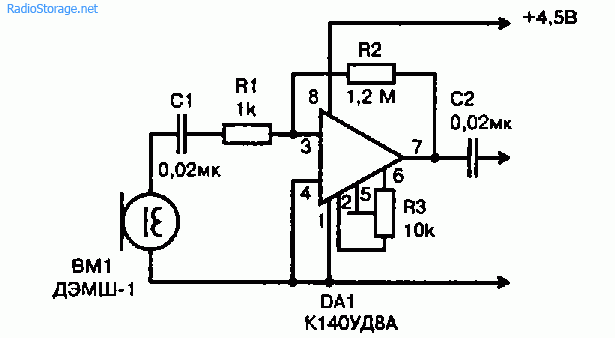
Rice. 4. Schematic diagram of the inclusion of an electromagnetic microphone at the input of the ultrasonic frequency converter on an operational amplifier.
Electret microphones
Recently, electret condenser microphones have been used in household tape recorders. Electret microphones have the widest frequency range - 30 ... 20,000 Hz.
Microphones of this type produce an electrical signal twice as large as conventional carbon microphones.
The industry produces electret microphones MKE-82 and MKE-01 in dimensions similar to the carbon MK-59 and the like, which can be installed in ordinary telephone handsets instead of coal ones without any alteration of the telephone set.
This type of microphone is significantly cheaper than conventional condenser microphones and therefore more readily available to radio amateurs.
The domestic industry produces a wide range of electret microphones, among them MKE-2 one-way directional for reel-to-reel tape recorders of the 1st class and for embedding in electronic equipment - MKE-3, MKE-332 and MKE-333.
For radio amateurs, the most interesting is the MKE-3 condenser electret microphone, which has a microminiature design.
The microphone is used as a built-in device in domestic tape recorders, radio and radio tape recorders, such as Sigma-VEF-260, Tom-303, Romantic-306, etc.
The MKE-3 microphone is manufactured in a plastic case with a flange for mounting on the front panel of a radio device from the inside. The microphone is omnidirectional and has a circle pattern.
The microphone is resistant to shocks and strong shaking. Table 2 shows the main technical parameters of some brands of miniature condenser electret microphones.
Table 2.
| Microphone type | FEM-3 | MKE-332 | MKE-333 | MKE-84 |
| Nominal range working frequencies, Hz |
50...16000 | 50... 15000 | 50... 15000 | 300...3400 |
| Sensitivity to free field on frequency 1000 Hz, μV / Pa |
no more than 3 | not less than 3 | not less than 3 | A - 6 ... 12 B - 10 ... 20 |
| Unevenness frequency response sensitivity in range 50 ... 16000 Hz, dB, not less |
10 | - | - | - |
| Complete module electrical resistance at 1000 Hz, Ohm, no more |
250 | 600 ± 120 | 600 ± 120 | - |
| Equivalent level sound pressure, due to its own microphone noise, dB, no more |
25 | - | - | - |
| Average level difference sensitivity "Front - rear", dB |
- | not less than 12 | no more than 3 | - |
| Operating conditions: temperature, С relative humidity air, no more |
5...30 85% at 20 "C |
-10...+50 95 ± 3% at 25 "C |
10...+50 95 ± 3% at 25 "C |
0...+45 93% at 25 "C |
| Supply voltage, V | - | 1,5...9 | 1,5...9 | 1,3...4,5 |
| Weight, g | 8 | 1 | 1 | 8 |
| dimensions (diameter x length), mm |
14x22 | 10.5 x 6.5 | 10.5 x 6.5 | 22.4x9.7 |
In fig. 5 shows a diagram of the inclusion of an electret microphone of the MKE-3 type, which is widespread in amateur radio designs.

Rice. 5. Schematic diagram of turning on a microphone of the MKE-3 type at the input of a transistor ultrasonic frequency converter.

Rice. 6. Photo and internal schematic diagram of the MKE-3 microphone, arrangement of colored conductors.
Carbon microphones
Despite the fact that carbon microphones are gradually being replaced by other types of microphones, but due to the simplicity of design and sufficiently high sensitivity, they still find their place in various communication devices.
The most common are carbon microphones, the so-called telephone capsules, in particular, MK-10, MK-16, MK-59, etc.
The simplest circuit for turning on a carbon microphone is shown in Fig. 7. In this circuit, the transformer must be a step-up and for a carbon microphone with a resistance R = 300 ... 400 Ohm it can be wound on an E-shaped iron core with a cross section of 1 ... 1.5 cm2.
The primary winding (I) contains 200 turns of PEV-1 wire with a diameter of 0.2 mm, and the secondary (II) - 400 turns of PEV-1 with a diameter of 0.08 ... 0.1 mm.
Carbon microphones, depending on their dynamic resistance, are divided into 3 groups:
- low-impedance (about 50 Ohm) with a supply current of up to 80 mA;
- medium-resistance (70 ... 150 Ohm) with a supply current of no more than 50 mA;
- high-resistance (150 ... 300 Ohm) with a supply current of no more than 25 mA.
From this it follows that in the carbon microphone circuit it is necessary to set the current corresponding to the type of microphone. Otherwise, when the current is high, the carbon powder will start to bake and the microphone will deteriorate.
In this case, nonlinear distortions appear. At a very low current, the sensitivity of the microphone decreases sharply. Carbon capsules can also operate at reduced power supply current, particularly in tube and transistor amplifiers.
The decrease in sensitivity with reduced microphone power is compensated for by simply increasing the gain of the audio amplifier.
In this case, the frequency response is improved, the noise level is significantly reduced, and the stability and reliability of operation are increased.

Rice. 7. Schematic diagram of turning on a carbon microphone using a transformer.
A variant of including a carbon microphone in a transistor amplifier stage is shown in Fig. 8.
The option of turning on a carbon microphone in combination with a transistor at the input of an audio-frequency tube amplifier according to the scheme in Fig. 9 allows a high voltage gain to be obtained.

Rice. 8. Schematic diagram of the inclusion of a carbon microphone at the input of a transistor ultrasonic frequency converter.

Rice. 9. Schematic diagram of switching on a carbon microphone at the input of a hybrid ultrasonic frequency converter, assembled on a transistor and an electronic tube.
Literature: V.M. Pestrikov - Encyclopedia of radio amateurs.
Has been hovering in my head for a long time. Gathering his strength, he began to search for amplifier circuits. Most of the circuits that I reviewed, which I did not like. I wanted to assemble it easier, better and less (for a laptop, because the built-in was done, apparently, just for show - the quality is bad). And after a short search, a phantom-powered microphone signal amplifier circuit was found and tested. Phantom power (this is when power and information transfer is carried out over one wire) is a huge plus of this scheme, because it saves us from third-party power supplies and the problems associated with them. For example: if we power the amplifier from a simple battery, then sooner or later it will run out, which will lead to the inoperability of the circuit at the moment; if we power it from a battery, then sooner or later it will have to be charged, which will also lead to some difficulties and unnecessary movements; if we power it from a power supply, then there are two minuses, which, in my opinion, discard the option of using it - these are wires (for powering our PA) and interference. You can get rid of interference in many ways (put a stabilizer, all kinds of filters, etc.), then it is not so easy to get rid of the wires (you can, however, make the transmission of energy at a distance, but why fence a whole complex of devices, for powering some the microphone amplifier?) and it also reduces the practicality of the device. Let's move on to the diagram:
A variant of the amplifier circuit for a dynamic microphone

The circuit is distinguished by its super-simplicity and mega-repeatability, in the circuit there are two resistors (R1, 2), two capacitors (C2, 3), a 3.5 plug (J1), one electret microphone and a transistor. Condenser C3 acts as a microphone filter. The capacity of C2 should not be neglected, that is, it is not necessary to set either more or less of the nominal value indicated in the diagram, otherwise it will entail a lot of interference. We put the T1 transistor domestic kt3102
... To reduce the size of the device, I used an SMD transistor marked "1Ks". If you don’t know how to solder at all - go to the forum.

When replacing T1, there were no significant changes in quality. All other parts are also in SMD cases, including the capacitor C3. The whole board turned out to be rather small, although it can be made even smaller using the technology of manufacturing LUT printed circuit boards. But he got along with a simple half-millimeter permanent marker. I etched the board in ferric chloride in 5 minutes. The result is such a microphone amplifier board, which is attached to the 3.5 plug.

All this fits well inside the casing from the plug. If you also do this, then I advise you to make the board as small as possible, since in my case it deformed the casing and changed its shape. It is advisable to rinse the board with a solvent or acetone. As a result, we got such a useful device with good sensitivity:

Before connecting the microphone to the computer, check all the contacts and whether there is a + 5v power supply at the microphone input (and it should be), in order to avoid comments like: "I assembled exactly as in the circuit, but it does not work!". This can be done like this: connect a new plug to the microphone connector and measure the voltage with a voltmeter between ground (large tap) and two short soldering taps. Just in case, try not to short-circuit the plug leads between each other when you measure the voltage. I don’t know what will happen then, and I don’t want to check. My microphone amplifier has been working for 3 months already, I am completely satisfied with the quality and sensitivity. Collect and unsubscribe on the forum about your results, questions, and maybe even about improvements to the case, circuitry and methods of their manufacture. I was with you BFG5000, good luck!
Discuss the article ELECTRIC MICROPHONE AMPLIFIER