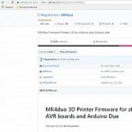
I have been using Marlin Kimbra (MagoKimbra / MK4duo) firmware for a long time (about half a year).
this is a revised Marlin firmware by the Italian RepRap community. The firmware is interesting in that it can be run on both 8-bit brains and 32-bit brains on the Arduino DUE board in conjunction with the low-budget RAMPS4Due.
You can download the firmware and see the list of its features at the official firmware address on the github.

I also want to say that compared to the classic Marlin, the firmware is much easier to configure. This is due to the fact that all the settings are grouped into different tabs. No need to dig a huge config footcloth. Very comfortably.
The firmware works on my printer, no problem. I periodically update the firmware, usually together with the release of the next version.
If you want to change the firmware, try it. I think you will like it.
After changing the firmware from Marlin to MagoKimbra, the first step is to clear the EEPROM by command
M502 - Revert to the default "factory settings". You still need to store them in EEPROM afterwards if you want to.
M500 - Store parameters in EEPROM
The site theoretically has a certain firmware configurator, but I have never used it. I tried, but he's some kind of crustacean. As a result, it is easier to configure everything by hand.
I will briefly tell you how to set up the firmware using the example of my printer, brains like an arduino mega + ramps sandwich and Cartesian kinematics (Prusa i3). I activate the minimum number of features necessary for work.
There is nothing particularly complicated in setting up the firmware, everything is intuitive.
I will also pay attention BRAINS Prusa i3 by flsun3d ... The printer comes with a single motherboard RAMPS 1.4 Plus


If you spill in it a firmware different from the one sent by the Chinese (Marlin 1.0.0), the display will automatically stop working for the printer and the extruder from E0 will move to E1. I ran into such a problem, sat around the evening and found a solution. At the end of the article, I'll tell you how to fix it.
The firmware builds without problems in the latest Arduino environment (1.8.1).
Open the MK4duo.ino file using the Arduino environment and start configuring.
We start with a tab Configuration_Basic.h
Here we will configure
* - Type of serial communications
* - Motherboard
* - Type of mechanics (Cartesian for Prusa I3)
* - Number of extruders
Right off the bat
#define BAUDRATE 250000
If hunting in the terminal (or Pronterface) see who configured the firmware
#define STRING_CONFIG_H_AUTHOR "(Mef73, custom config)"
Or you can leave it alone.
There is nothing more to do in this tab, because by default it is already enabled
#define MOTHERBOARD BOARD_RAMPS_13_HFB
#define MECHANISM MECH_CARTESIAN
And also installed one extruder and one driver for the extruder.
Go to the tab Configuration_Cartesian.h
I will start by changing the name of the printer, although this is not necessary
#define CUSTOM_MACHINE_NAME "Prusa I3 flsun"
#define INVERT_E0_DIR true
It is my standard extruder of the Prusa i3 printer from flsun3d that is inverted. You can flip the stepper motor connector (SM), but I don't want to. So that when I change the brains of the printer, I do not warm my head at the expense of turning the engine connector.
Again, for my printer with drv8825 and microstep 32
#define DEFAULT_AXIS_STEPS_PER_UNIT (200, 200, 800, 310, 310, 310, 310) // drv8825
For my printer with a4988 and microstep 16
#define DEFAULT_AXIS_STEPS_PER_UNIT (100, 100, 400, 155, 155, 155, 155) // a4988
You only need to write ONE line. For one or another stepper motor driver.
For the rest I correct
#define DEFAULT_MAX_FEEDRATE (200, 200, 2, 100, 100, 100, 100)
#define DEFAULT_MAX_ACCELERATION (1500, 1500, 50, 1000, 1000, 1000, 1000)
#define DEFAULT_ACCELERATION 1500
#define DEFAULT_XJERK 30.0
#define DEFAULT_YJERK 30.0
#define DEFAULT_ZJERK 0.4
You can also put your own values. On this with a tab Configuration_Cartesian.h we finish.
Go to the tab Configuration_Feature.h
Here we configure all sorts of firmware features. I'll tell you what and where I turn it on. Perhaps someone in the comments will tell you what else he uses. In fact, I use a minimum of any features, only what I need.
So let's go ...
Remove // \u200b\u200bc
#define HOME_Y_BEFORE_X
We park the Y-axis first. I have a mirror with clamps, if I park the X-axis first at a low height Z with a nozzle I will demolish the clamps.
#define FORCE_HOME_XY_BEFORE_Z
z-axis parked last
Now we go down to
// \u003d\u003d\u003d\u003d\u003d\u003d\u003d\u003d\u003d\u003d\u003d\u003d\u003d\u003d\u003d\u003d\u003d\u003d\u003d\u003d\u003d\u003d\u003d\u003d\u003d\u003d\u003d\u003d\u003d\u003d ADDON FEATURES \u003d\u003d\u003d\u003d\u003d\u003d\u003d\u003d\u003d\u003d\u003d\u003d\u003d\u003d\u003d\u003d\u003d \u003d\u003d\u003d\u003d\u003d\u003d\u003d\u003d\u003d\u003d\u003d\u003d\u003d
Let's uncomment
#define EEPROM_SETTINGS
#define EEPROM_CHITCHAT
#define SDSUPPORT
#define SD_SETTINGS
by activating EEPROM and SD card support
I have a character display, 2004, reprap discount smart controller
#define ULTRA_LCD
#define ENCODER_PULSES_PER_STEP 4
#define ENCODER_STEPS_PER_MENU_ITEM 1
#define REVERSE_ENCODER_DIRECTION
#define LCD_FEEDBACK_FREQUENCY_DURATION_MS 40
#define LCD_FEEDBACK_FREQUENCY_HZ 2000
With these parameters, both Chinese reprap discount smart controllers work well for me.
#define LCD_INFO_MENU
#define REPRAP_DISCOUNT_SMART_CONTROLLER
If you have an Arduino DUE, pay attention here:
// \u003d\u003d\u003d\u003d\u003d\u003d\u003d\u003d\u003d\u003d\u003d\u003d\u003d\u003d\u003d\u003d\u003d\u003d\u003d\u003d\u003d\u003d\u003d\u003d\u003d\u003d\u003d\u003d\u003d ADVANCED FEATURES \u003d\u003d\u003d\u003d\u003d\u003d\u003d\u003d\u003d\u003d\u003d\u003d\u003d\u003d\u003d\u003d\u003d \u003d\u003d\u003d\u003d\u003d\u003d\u003d\u003d\u003d\u003d
//===========================================================================
/****************************************************************************************
************************************* Buffer stuff ********** **************************
****************************************************************************************/
// The number of linear motions that can be in the plan at any give time.
// THE BLOCK BUFFER SIZE NEEDS TO BE A POWER OF 2, i.g. 8,16,32 because shifts and ors are used to do the ring-buffering.
// For Arduino DUE setting BLOCK BUFFER SIZE to 32
#define BLOCK_BUFFER_SIZE 16
// The ASCII buffer for receiving from the serial:
#define MAX_CMD_SIZE 96
// For Arduino DUE setting to 8
#define BUFSIZE 4
In general, this and all the settings that differ in Mega and DUE, I did not find others.
Go to the tab Configuration_Temperature.h
#define TEMP_SENSOR_BED 1
The table is heated, and by default, the heating thermistor is disabled in the firmware
Go to ********************** PID Settings - HOTEND ********************** ****
#define DEFAULT_Kp (14.17, 40, 40, 40) // Kp for H0, H1, H2, H3
#define DEFAULT_Ki (01.55, 07, 07, 07) // Ki for H0, H1, H2, H3
#define DEFAULT_Kd (32.29, 60, 60, 60) // Kd for H0, H1, H2, H3
After flashing, I will definitely recalibrate Kp Ki Kd on command
M303 H0 C8 S240 U
We go down to ************************ PID Settings - BED ********************* *******
My table is also regulated by PID. Bang Bang is simpler, but not as accurate. Therefore, we will uncomment
#define PIDTEMPBED
#define DEFAULT_bedKp 88.21
#define DEFAULT_bedKi 12.77
#define DEFAULT_bedKd 152.28
These are the settings once obtained experimentally for my printer.
After flashing, I will definitely recalibrate the Kp Ki Kd of the table by command
M303 H-1 C8 S100 U
In Pronterface or without even bothering, in the Octoprint terminal. The U key will apply the result immediately.
If the heating falls off by the timer and gives an error, I repeat the command.
Then you need to execute the command
To protect the hot end and the table from overheating, I will uncomment
#define THERMAL_PROTECTION_HOTENDS
#define THERMAL_PROTECTION_BED
That's all.
I have a homemade Fan Extender installed on my board, for 1 channel, and it lives on pin 11. I connected a fan for blowing a thermal barrier to it.
In the tab Configuration_Feature.h
We remove // \u200b\u200bfrom
#define HOTEND_AUTO_FAN
#define HOTEND_AUTO_FAN_TEMPERATURE 45
I set the response temperature to 45 degrees
In order for the feature to work, in the tab Configuration_Pins.h
#if ENABLED (HOTEND_AUTO_FAN)
#define H0_AUTO_FAN_PIN 11
I point out that the fan control lives on port 11.
Now I'll tell you about a wonderful board RAMPS 1.4 Plus... The board is supplied with the Prusa I3 Flsun3d printer.
The pins on the board do not match the original RAMPS 1.4 sandwich. !!!
I rummaged through the firmware from the Chinese and found differences in the pins.
We put it in a folder
MK4duo-masterMK4duosrcboards
replacing the original file 99.h.
And now in the Configuration_Basic.h tab
put // in front of MOTHERBOARD BOARD_RAMPS_13_HFB
// # define MOTHERBOARD BOARD_RAMPS_13_HFB
#define MOTHERBOARD BOARD_99
Our RAMPS 1.4 Plus board is now BOARD_99
This is the board number reserved in the firmware, I think just for such a case.
After that, life is getting better on RAMPS 1.4 Plus. The display starts working and everything else is as it should be.
By analogy with the settings in the file, you can configure the board in classic Marlin. I did it too.
MagoKimbra / MK4duo Firmware, Firmware Settings for Prusa i3 for RAMPS 1.4 Sandwich and for RAMPS 1.4 Plus Board
i mentioned that installing a driver on the extruder that gives a microstep of 1/32 is quite a useful thing (although the benefit is revealed by a device that does not have a mark on verification in the metrology department, in other words, a fingernail!). However, after that you may want to replace all drivers with similar ones. I've read in many forums that this makes the sound of the engines more musical. I would like to say: Everything is good in moderation. Not that it was completely bad, but let me describe the arguments that appeared after digging into the bowels of the Marlin firmware, because it is she who is used as the base in many 3D printers.
Where to begin? First, I'll talk about acceleration. They will be useful to us, but they cannot be inserted into the text anywhere, the narrative will be torn everywhere. So let this be like an introduction. If you jerk the head sharply, there will be a lot of problems. Starting from the low-frequency printing noises, which have already set the teeth on edge in previous articles, and ending with the fact that the engine can skip a few steps at a sharp start. To avoid all this, the head is accelerated smoothly. Well, and they slow down - too, there it is already needed to reduce noise. The Marlin firmware operates in a trapezoidal speed graph mode.
That is, the speed rises and falls linearly in a certain area. The angle at which the speed graph is tilted during acceleration and deceleration is precisely set by the "Acceleration" parameter. This is how the drop in the step frequency looks on the oscilloscope (red bursts are the steps of the motor along the X axis, yellow ones - the extruder motor, I saved this oscillogram when, when fighting RF ringing, I was convinced that the extruder really steps twice as often as before:

Now let's talk about how fast our engine is walking. Let's ask the printer itself through the communication panel. I work in Simplify3D, but there is such a panel in other programs:

Just turn off the annoying temperature messages. We remove this checkbox:

We return to the Communication tab, now the inscriptions do not flicker (the old ones, however, remained in place, but it does not matter). We speak to the printer M503 and press SEND

The printer brought out a lot of things, and in human language. We are interested in this line:
RECEIVED: echo: Steps per unit:
Steps per unit:
RECEIVED: echo: M92 X100.00 Y100.00 Z1600.00 E100.00
M92 X100.00 Y100.00 Z1600.00 E100.00
It turns out that my X and Y axes have 100 steps per millimeter. Well, more precisely, microsteps.
Wonderful. What does it mean? This means that to move the head 1 millimeter, the X and Y motors must take 100 steps. In general, much more information was released there, read it, this is a very funny thing. The parameters can be changed and saved in the EEPROM, but more on that some other time.
Let the head move at a speed of 100 mm / s. Then she should take 100 * 100 \u003d 10,000 steps per second. That is, the motor runs at 10 kilohertz. 150 mm / s - 15 kilohertz, etc. The numbers may be slightly different, they depend on which gear wheels are on the engines.
From the text of the firmware, I learned that in theory there are printers MZ3D-256A and MZ3D-256B, they have a different number of steps. But let's consider, as another example, not hypothetical A and B, but a real MakerGear M2 printer, it has 88.8 steps per millimeter, then 100 mm / s will be 8.88 kilohertz, 150 mm / s - about 13 kilohertz. In general, ask your printer, he will answer you what parameters he personally have.
Actually, if I increase the microstep of the motor from 16 to 32 steps, then the frequencies of my printer will increase to 20 and 30 kilohertz, and for the M2 (from its 88.8) to 17 and 26 kilohertz, respectively. Is it a lot or a little? Let's turn to the firmware.
What do we see in the Marlin firmware? And we see that the engines are served by timer 1. One tick of the timer - one step. Then the processor stops working with the motors until the next tick. But Marlin is a very tricky firmware! She sets up the timer so that the next tick occurs exactly on time! For this, the function is called
unsigned short calc_timer (unsigned short step_rate) (
As you can see, the frequency of the engine is transmitted to it. And what do we see at the entrance? Oooo! First we meet the harmless
if (step_rate\u003e MAX_STEP_FREQUENCY) step_rate \u003d MAX_STEP_FREQUENCY;
Well, here it is checked that the frequency is not higher than 40 KHz (for my printer in its native version it is 400 mm / s, but if I do a microstep of 1/32, then only 200 mm / s). Further more
if (step_rate\u003e 20000 ) (// If steprate\u003e 20kHz \u003e\u003e step 4 times
Step_rate \u003d (step_rate \u003e\u003e 2)
Step_loops \u003d 4;
Else if (step_rate\u003e 10000 ) (// If steprate\u003e 10kHz \u003e\u003e step 2 times
Step_rate \u003d (step_rate \u003e\u003e 1)
Step_loops \u003d 2;
Else (
Step_loops \u003d 1;
I am translating into Russian: The performance of the AtMega processor is not enough to service the timer interrupt at a frequency above 10 KHz. Therefore, if the motor operates at a speed of up to 10 KHz, there will be one step per interruption. From 10 to 20 GKts - there will be two steps per interruption. And from 20 to 40 kHz - four steps.
Actually, the conclusion of the article is precisely that everything below 10 KHz (100 mm / s for my printer) in the Marlin firmware running on the AtMega controller (in the Arduino) will be processed evenly. Above - the steps will be uneven. Two steps, a pause, two steps again, a pause again. Or even four steps, a pause, another four steps, another pause.
For (int8_t i \u003d 0; i< step_loops; i++) { // Take multiple steps per interrupt (For high speed moves)
If (counter_x\u003e 0) (
#ifdef DUAL_X_CARRIAGE
If (extruder_duplication_enabled) (
Else (
If (current_block-\u003e active_extruder! \u003d 0)
WRITE (X2_STEP_PIN,! INVERT_X_STEP_PIN);
Else
WRITE (X_STEP_PIN,! INVERT_X_STEP_PIN);
#else
WRITE (X_STEP_PIN,! INVERT_X_STEP_PIN);
#endif
Counter_x - \u003d current_block-\u003e step_event_count;
Count_position + \u003d count_direction;
delayMicroseconds (2);
// Same for Y, Z and Extruder
In general, at microstep 1/32, the motors become more musical, but they are clearly jerky.
Can uniformity be done? On Arduino - not sure. You can drag it all to ARM, where the processor itself is faster, and multiplication / division is performed in hardware, therefore it works faster (and along the way, you can throw out the assembler inserts and part of the table calculations - this is in AVR without them, ARM already has a compiler converting the C code to acceptable assembly commands without our help). And some Cortexes also support floating arithmetic in hardware (the firmware simply abounds in such calculations). Personally, I managed to do it roughly in exactly one week, so everything is real (clean - still sawing and sawing, of course). Just don’t think that now we will redo these comparisons, and everything will work! Ha! There, check on check and check drives. Let's say here's the end of that calc_timer function:
if (timer< 100) { timer = 100; MYSERIAL.print(MSG_STEPPER_TOO_HIGH); MYSERIAL.println(step_rate); }//(20kHz this should never happen)
Return timer;
That is, if the tick frequency of the timer is higher than 20 KHz, it will be reduced here. In general, it may be necessary to check the places where certain restrictions are encountered. Here, for example, is the function for calculating the movement of the head, taking into account acceleration (it was for the sake of it that I cited the theory of trapezoidal speeds)
void calculate_trapezoid_for_block (block_t * block, float entry_factor, float exit_factor) (
Unsigned long initial_rate \u003d ceil (block-\u003e nominal_rate * entry_factor); // (step / min)
Unsigned long final_rate \u003d ceil (block-\u003e nominal_rate * exit_factor); // (step / min)
// Limit minimal step rate (Otherwise the timer will overflow.)
If (initial_rate<120) {
Initial_rate \u003d 120;
If (final_rate< 120) {
Final_rate \u003d 120;
True, the minimum speed is used here so that the 16-bit timer does not overflow. However, this shows that checks can be hidden anywhere in the code. It is not easy to keep the engines musical! However, in principle, everything is real. But not that we bought new drivers, corrected a couple of constants and that's it. That musicality is beautiful, but deceiving.
Conclusion
The article shows that it is not a fact that it makes sense to replace the drivers of the travel motors X and Y with supporting microstep 1/32. When using an Arduino (with an AVR based controller), the cadence may not be entirely fair if it is over 10 kHz. Checking the honesty of steps for the ARM processor is still in the active phase, but it is already known for sure that at least you will have to remove or change the restrictions in the firmware.
Before starting work with a non-professional or semi-professional 3D printer, as well as a Kit-set for self-assembly, it is often necessary to "fill" and configure the firmware. Firmware is a program code, the main tasks of which are: reading and reproducing G-code, controlling the printer through various interfaces, displaying information about the printing process. In other words, the firmware is needed to make the hardware and the set of electronics "come to life" and can be controlled. The firmware is uploaded to the control board. Different 3D printers have different control boards, respectively, the firmware is also different.
Our Prusa i3 Steel 3D printers use a bundle of Arduino Mega 2560 and Ramps 1.4 boards, so in this article we will take a closer look and analyze the settings of the firmware suitable for them, Marlin.
If you have not yet collected electronics, then check out the article:
This firmware is one of the most popular, also because the developers regularly add new features to it: automatic gap adjustment, bar end sensor and much more. Moreover, this firmware is absolutely free and can be downloaded from the official website.
Where to get?
The latest version of the Marlin firmware is available on the official website of the developer https://github.com/MarlinFirmware/Marlin. You can download an earlier firmware version from the link. There are also many different versions on the site, but we recommend downloading the latest version marked as Latest release. At the time of this writing, this version is 1.0.2-2
Under Downdloads, click on Source code (zip) and download the firmware archive to your computer. Next, extract the contents of the archive into a folder.
Installing Arduino IDE
After you have downloaded the firmware, you need to edit it and then write it to the microcontroller of the control board (Arduino mega 2560). For these purposes, you need the Arduino IDE program, which can be downloaded for free from the Arduino official website.
Note! This Arduino IDE program is regularly updated and it is possible that when uploading the firmware to the board, problems may arise with new versions of the Arduino IDE, namely, errors will come out, and you will not be able to write the firmware to the microcontroller. Therefore, if problems arise, try downloading an older version of the program, for example, version 1.6.0)
For reliability, you can immediately download the tested version 1.6.0

Click on Windows Installer, and you will be redirected to another page, where you need to click on the JUST DOWNLOAD button, then the download of the file will begin. Install the program and proceed to the next step.
Editing Marlin Firmware
You have downloaded directly the Marlin firmware itself and the Arduino IDE program with which you can edit. Open the "Marlin" firmware folder, find the "Marlin" file with the .ino extension

Open this file, the Arduino IDE will open

At the top of the program window there are many tabs, each of which contains pieces of code, on which the operation of the 3D printer depends. You only need a few main tabs. The first and main tab is "Configuration.h"

This is a configuration file that contains basic settings. It is in this tab that you need to make the main changes.
Note! Perform all changes in the firmware in order from top to bottom. These changes will affect the main sections of the code, and they are necessary for the initial launch of your 3D printer.
Set the required baud rate
The first thing to change is the baud rate. By default, the speed is 250,000 (47 lines of code)
// This determines the communication speed of the printer #define BAUDRATE 250000

// This determines the communication speed of the printer #define BAUDRATE 115200
If you are using a board, then the speed should be 250,000.
Choosing a control board
After setting the baud rate, you must specify the used control board (55 lines of code).
#ifndef MOTHERBOARD #define MOTHERBOARD BOARD_ULTIMAKER #endif

By default, the Ultimaker 3D printer board is BOARD_ULTIMAKER, so you need to change the board. The entire list of boards is in the "BOARDS_H" tab

There is a huge list of different boards provided, but you only need the following:
#define BOARD_RAMPS_13_EFB 33 // RAMPS 1.3 / 1.4 (Power outputs: Extruder, Fan, Bed)
#define BOARD_RAMPS_13_EEB 34 // RAMPS 1.3 / 1.4 (Power outputs: Extruder0, Extruder1, Bed)
#define BOARD_RAMPS_13_EFF 35 // RAMPS 1.3 / 1.4 (Power outputs: Extruder, Fan, Fan)
#define BOARD_RAMPS_13_EEF 36 // RAMPS 1.3 / 1.4 (Power outputs: Extruder0, Extruder1, Fan)
These boards are for Arduino mega 2560 and Ramps 1.4. Depending on the modification of your 3D printer, you must select the appropriate board. For example, a standard bundle of 1 extruder + blowing of the working area + heating table corresponds to the BOARD_RAMPS_13_EFB board
The name of the board must be copied and replaced in the "Configuration.h" tab, change the following lines:

Changing the name of the 3D printer
When setting up, be sure to come up with a name for your 3D printer and indicate this in the firmware. What for? The name of the printer is displayed on its LCD display, such a possibility is precisely provided on such a display.
Find stitches: (59 lines)
// #define CUSTOM_MENDEL_NAME "This Mendel"
The #define is preceded by "//" - this means that these lines are not used in the code, but serve as explanations. To activate this line, you need to uncomment the line, remove // \u200b\u200bin front of the line.
Change the default name "This Mendel" to your 3D printer name, for example "P3Steel". We get the following:
Choosing a temperature sensor for the table and extruder
Above, the firmware settings for 1 extruder and a heating table were indicated, that is, there are two heating elements in the 3D printer, the temperatures of which must be regulated. Temperature control is carried out using temperature sensors - thermistors.
There are a large number of different thermistors with different characteristics, so you must specify in the firmware which thermistor you have. This is necessary for the printer to show the correct temperature in the future. Find the list of supported thermistors in the firmware:
//// Temperature sensor settings: // -2 is thermocouple with MAX6675 (only for sensor 0) // -1 is thermocouple with AD595 // 0 is not used // 1 is 100k thermistor - best choice for EPCOS 100k (4.7 k pullup) // 2 is 200k thermistor - ATC Semitec 204GT-2 (4.7k pullup) // 3 is Mendel-parts thermistor (4.7k pullup) // 4 is 10k thermistor !! do not use it for a hotend. It gives bad resolution at high temp. !! // 5 is 100K thermistor - ATC Semitec 104GT-2 (Used in ParCan & J-Head) (4.7k pullup) // 6 is 100k EPCOS - Not as accurate as table 1 (created using a fluke thermocouple) (4.7k pullup ) // 7 is 100k Honeywell thermistor 135-104LAG-J01 (4.7k pullup) // 71 is 100k Honeywell thermistor 135-104LAF-J01 (4.7k pullup) // 8 is 100k 0603 SMD Vishay NTCS0603E3104FXT (4.7k pullup) / / 9 is 100k GE Sensing AL03006-58.2K-97-G1 (4.7k pullup) // 10 is 100k RS thermistor 198-961 (4.7k pullup) // 11 is 100k beta 3950 1% thermistor (4.7k pullup) / / 12 is 100k 0603 SMD Vishay NTCS0603E3104FXT (4.7k pullup) (calibrated for Makibox hot bed) // 13 is 100k Hisens 3950 1% up to 300 ° C for hotend "Simple ONE" & "Hotend" All In ONE "// 20 is the PT100 circuit found in the Ultimainboard V2.x // 60 is 100k Maker "s Tool Works Kapton Bed Thermistor beta \u003d 3950 // // 1k ohm pullup tables - This is not normal, you would have to have changed out your 4.7k for 1k // (but gives greater accuracy and more stable PID) // 51 is 100k thermistor - EPCOS (1k pullup) // 52 is 200k thermistor - ATC Semitec 204GT-2 (1k pullup) // 55 is 100k thermistor - ATC Semitec 104GT-2 (Used in ParCan & J-Head) (1k pullup) / / // 1047 is Pt1000 with 4k7 pullup // 1010 is Pt1000 with 1k pullup (non standard) // 147 is Pt100 with 4k7 pullup // 110 is Pt100 with 1k pullup (non standard)
Find your own in the list, remember the number on the left. As a rule, many people use a Chinese 100 kΩ thermistor, thermistor number "1" is suitable for it.
// 1 is 100k thermistor - best choice for EPCOS 100k (4.7k pullup)
Make changes where you want (lines 115-118)
#define TEMP_SENSOR_0 -1 #define TEMP_SENSOR_1 -1 #define TEMP_SENSOR_2 0 #define TEMP_SENSOR_BED 0
By default, the first two thermistors are activated in the firmware:
TEMP_SENSOR_0 - responsible for the thermistor of the first extruder
TEMP_SENSOR_1 - responsible for the thermistor of the second extruder
TEMP_SENSOR_BED - responsible for the table thermistor
Change the lines and get the following:

TEMP_SENSOR_1 and TEMP_SENSOR_2 are not used, so we put "0" zeros in front of them.
Maximum temperature limitation
To limit the maximum temperature, the following lines are required (140-143)
#define HEATER_0_MAXTEMP 275 #define HEATER_1_MAXTEMP 275 #define HEATER_2_MAXTEMP 275 #define BED_MAXTEMP 150
The numbers on the right, namely 275 and 150, are the maximum temperatures of the extruder and the heating table, respectively.
When the temperature exceeds the maximum Temp, your heater will be turned off. This feature is there to protect your extruder from accidental overheating. If you use a hot-end with Teflon inside, we recommend limiting the temperature to 260 degrees.
Minimum temperature limitation
Also in the firmware, the default is to limit the minimum extruder temperature to 170 degrees. This means that if the temperature of the extruder is below 170 degrees, the extruder motor will not rotate and the plastic will not be fed. Protection against pushing through unheated plastic (line 230).
#define EXTRUDE_MINTEMP 170
If you want to disable this function, then put "//" in front of the line
Setting the limit switches
Configuring the logic of the limit switches
First of all, what you need to pay attention to is which limit switches you use and what is their principle of operation. In the firmware, it is necessary to correctly indicate the logic of the limit switches. Find the following lines (301-306)
Const bool X_MIN_ENDSTOP_INVERTING \u003d true; // set to true to invert the logic of the endstop. const bool Y_MIN_ENDSTOP_INVERTING \u003d true; // set to true to invert the logic of the endstop. const bool Z_MIN_ENDSTOP_INVERTING \u003d true; // set to true to invert the logic of the endstop. const bool X_MAX_ENDSTOP_INVERTING \u003d true; // set to true to invert the logic of the endstop. const bool Y_MAX_ENDSTOP_INVERTING \u003d true; // set to true to invert the logic of the endstop. const bool Z_MAX_ENDSTOP_INVERTING \u003d true; // set to true to invert the logic of the endstop.
If you have mechanical limit switches, then when triggered, the circuit closes, set the values \u200b\u200b"true" in front of each line of the corresponding axis. If you use optical limit switches, then when triggered, the circuit is opened, opposite each line of the corresponding axis, set the values \u200b\u200b"false".
By default, the firmware opposite each limit switch is set to "true", which corresponds to mechanical limit switches.
After configuring the operation of the limit switches, you can check the command M119 in the console.
The text should come in response:
x_min: open - the trailer did not work;
x_min: TRIGGERED - trailer triggered.
Setting the "HOME" position - home
The firmware supports 3 pairs of limit switches: for each X, Y and Z axis, two limit switches min and max. As a rule, limit switches are installed only for the minimum position of each axis, and the maximum is set in the firmware.
The home position (initial position) will be in the minimum positions of the limit switches and this is set in the firmware: (lines 337-339)
#define X_HOME_DIR -1 #define Y_HOME_DIR -1 #define Z_HOME_DIR -1
Changing the direction of rotation of motors
When assembling a 3D printer, namely when connecting stepper motors to the board, the following situation is possible: when you have configured and connected everything, when you press "home", the carriage of one of the axes goes in the other direction (not to the limit switch), then it is necessary turn the stepper motor connector 180 degrees or change the values \u200b\u200bin the firmware:
#define INVERT_X_DIR true // for Mendel set to false, for Orca set to true #define INVERT_Y_DIR false // for Mendel set to true, for Orca set to false #define INVERT_Z_DIR true // for Mendel set to false, for Orca set to true #define INVERT_E0_DIR false // for direct drive extruder v9 set to true, for geared extruder set to false #define INVERT_E1_DIR false // for direct drive extruder v9 set to true, for geared extruder set to false #define INVERT_E2_DIR false // for direct drive extruder v9 set to true, for geared extruder set to false
For example, if you have a Y-axis carriage in the other direction, then you need to find the line
#define INVERT_Y_DIR false // for Mendel set to true, for Orca set to false
and change "false" to "true". And so with each axis and extruder.
Setting the dimensions of movement
In order for the 3D printer to determine the working area, you must specify its dimensions in the firmware: (lines 345-350)
#define X_MAX_POS 205 #define X_MIN_POS 0 #define Y_MAX_POS 205 #define Y_MIN_POS 0 #define Z_MAX_POS 200 #define Z_MIN_POS 0
Opposite each line, specify the appropriate dimensions, by default the working area is set to 205x205x200 mm
Setting the steps of movement along the axes
Specifying the number of steps of stepper motors is one of the main firmware settings (line 490):
#define DEFAULT_AXIS_STEPS_PER_UNIT (78.7402,78.7402,200.0 * 8 / 3,760 * 1.1) // default steps per unit for Ultimaker
In brackets, separated by commas for each axis, the number of steps that the stepper motor must make for the carriage to travel 1 mm is indicated. Where to get these values? You can calculate or take already known ones.
Calculation of the X and Y axes (belts)
All axes have stepper motors 200 steps per revolution, 16 micro steps per step (this is set with jumpers on the board).
Along the X and Y axes, there is a 2 mm GT2 drive belt and 20-tooth pulleys.
It turns out:
(200*16)/(2.0*20)=80
The stepper motor has to take so many steps so that the X and Y axis travels exactly 1 mm.
If you have a Gt2 toothed pulley with a pitch of 2 mm and with 20 teeth, then the formula is:
(200*16)/(2.0*16)=100
Calculation of the Z axis (lead screw)
The Z axis can be:
- Stud M8 with a thread pitch of 1.25 mm, then the formula: 200 * 16 / 1.25 \u003d 2560
- Stud M5 with a pitch of 0.8 mm, then the formula: 200 * 16 / 0.8 \u003d 4000
- Trapezoidal screw with a diameter of 8 mm with a pitch of 1 mm and a lead of 1, then the formula: 200 * 16/1 \u003d 3200
- Trapezoidal screw with a diameter of 8 mm with a pitch of 2 mm and a lead of 1, then the formula: 200 * 16/2 \u003d 1600
- Trapezoidal screw with a diameter of 8 mm with a pitch of 2 mm and a lead of 4, then the formula: 200 * 16/2 * 4 \u003d 400
Pruse i3 Steel uses M5 studs, then the number is 4000.
Extruder calculation
The setting of the feed of the extruder depends on the reduction ratio and the diameter of the feed gear. The number of steps that the stepper motor of the extruder must take in order to push the plastic by 1 mm is selected experimentally after the first filling of the firmware into the 3D printer.
Unscrew the nozzle and reduce the minimum nozzle temperature limit to 5 degrees:
#define EXTRUDE_MINTEMP 5
The extruder will now run with a cold nozzle. Without changing the extruder settings, press to drive the plastic by 100 mm. Measure the length of the bar passed through the extruder with a ruler or vernier caliper.
When choosing an extruder setting, achieve an accurate figure for a reasonable bar length, for example 200 mm. After setting, reset the minimum temperature limits:
#define EXTRUDE_MINTEMP 170
Limiting the maximum speed of movement along the axes
#define DEFAULT_MAX_FEEDRATE (500, 500, 5, 25) // (mm / sec)By default, the speeds are 500,500.5, 25 mm / s on the X, Y, Z axes and the extruder, respectively. We recommend reducing the speed from 500 to 200.
Setting the acceleration of movements along the axes
Another important setting is the setting of accelerations for different axes, since due to the incorrect setting of this moment, there are often problems during printing, namely, displacement of layers due to skipping motor steps. If you put too much acceleration, then there will be gaps. By default, the firmware contains the following values:
#define DEFAULT_MAX_ACCELERATION (9000,9000,100,10000) // X, Y, Z, E maximum start speed for accelerated moves. E default values \u200b\u200bare good for Skeinforge 40+, for older versions raise them a lot. #define DEFAULT_ACCELERATION 3000 // X, Y, Z and E max acceleration in mm / s ^ 2 for printing moves #define DEFAULT_RETRACT_ACCELERATION 3000 // X, Y, Z and E max acceleration in mm / s ^ 2 for retracts
For the X and Y axes, accelerations are 9000 mm / s ^ 2 - this is a lot.
For the initial setting, set no more than 1000 and for DEFAULT_ACCELERATION set 1500 instead of 3000.
Display activation
The last thing left to do is activate the display you want. One of the most popular displays is. Find and uncomment the following lines:
#define ULTRA_LCD #define SDSUPPORT #define ULTIPANEL #define REPRAP_DISCOUNT_SMART_CONTROLLER
These lines should not be preceded by "//". You should get the following:

Fill firmware
After all the major changes to the firmware, you can upload it. In the Arduino IDE go to the "Tools" -\u003e "Board" tab and select "Arduino / Genuino Mega or Mega 2560"

And there you need to set the correct COM port of your 3D printer. To fill the firmware, click on the circle with the arrow.

The progress of the firmware upload is indicated by an indicator, and after successful completion, a confirmation message will appear on the screen.
Hello beginners and professionals!
I just came to the world of 3D printing and have very little experience in this business. But I would like to tell you something. Namely the idea of \u200b\u200bcalibrating the printer table.
The method does not take much time, does not require a rare measuring tool, is quite accurate and simple.
The idea of \u200b\u200bsuch a calibration arose after this picture:


As you can see from the pictures, the upper part of the border is printed well, glued together (0.2mm thickness), and the lower part is not glued (0.3mm thickness).
To calibrate the table you need:
A set of keys / screwdrivers for adjusting the table, who regulates what;
Vernier caliper (ideally with a vernier (scale) 0.05);
Model for the test - http: // site / 3d-models / detali-dlya-3d-printerov / raznoe / test_gorizont /

In my case, the table is adjusted with three screws, so the model looks like this. Each circle is near its own screw. L - Left, R - Right, Z - Back, C - center (to determine the curvature of the surface). Layer thickness 0.2 mm with a border. In your case, you can do it your way.
Model Element (Center):

Pre-calibration:
We take an A4 sheet and set up the table as described in many articles and videos on the Internet.
This method can be used to fine tune the table, but! You will not be able to detect sufficient / insufficient paper clamping force by touch. Easy sliding can be different for everyone.
In general, we have roughly adjusted it.
Final calibration:
We print the model. As you can see from the screenshot - it takes 2 minutes to print, taking into account deviations and warming up - 5 minutes.
We are waiting for the model to cool down to peel it off. I didn't wait, but just faked it with a stationery knife, ABS makes it possible.
Peel off the circles, take a caliper and measure the thickness. In my case, it should be 0.2 mm.
Based on the size deviations, you determine in which direction you need to twist or unscrew the table. Ensure that all circles have the same and desired thickness.
If there is a clear lack of pressure, when the threads do not stick together, I adjust during printing, until the threads begin to touch each other. Then I measure and make a control print of the model with measurements.
The center can be used once to define the convexity or concavity of the table. But sometimes it doesn't hurt to be in control.
Good luck and a calibrated table for everyone!
Critics and suggestions are welcome.
As you know, for high-quality printing on a 3D printer, it is necessary to carefully align the table surface. Unfortunately, this is not always possible. Quite often the table is a curved surface and even the use of glass does not completely solve this problem. Fortunately, the latest Marlin firmware is focusing more and more on the ability to calibrate the table surface. Fully automatic calibration requires the use of additional sensors, which is not always available, but besides it there is the possibility of manual calibration of the table. This is what I want to tell you about.
Adding auto-calibration support to the firmware
Enable manual calibration support
Setting grid options
Attention! Do not use more than 7 points per axis. This is a limitation of the firmware.
Adding items to the printer menu
Post-calibration script. Here, by default, some body movements by the extruder, not the fact that they are needed. I'm not sure about that.
| // #define Z_PROBE_END_SCRIPT "G1 Z10 F12000 \\ nG1 X15 Y330 \\ nG1 Z0.5 \\ nG1 Z10" |
After that, fill in the updated firmware.
Calibrate the table
For manual calibration, the so-called Mesh Bed Leveling (MBL) is used. Those. method of calibration by an array of points. Accordingly, the surface of the table is divided into a grid and the Z coordinates are measured at the grid nodes by manually moving the Z axis. Actually, only a sheet of paper and straight arms are needed for measurement.
At each point under the nozzle of the extruder we put a sheet of paper and by moving the Z axis (either by sending a special G command through the software from the computer, or through the printer menu) we achieve such a state when the sheet under the extruder can still be freely moved, and decreasing the position of the extruder by one step already interferes the sheet to move. After that, the current point is recorded and we continue from the next and so on until the end.
At the end of the process, when all points have been measured, we write the results into the nonvolatile memory of the printer and this is actually enough. In the future, you do not need to adjust the surface before each use - the saved values \u200b\u200bwill be used.
By default, a 3 × 3 grid is used for calibration, i.e. 9 points, but if desired, you can set a different number in the firmware (no more than 7 per axis, i.e. no more than 49 in total).
To further increase the accuracy of the calibration, you can warm up the table and the extruder to operating temperatures before performing it. This will take into account and compensate for thermal expansion.
Through an external program
There is a special command G29 for table calibration
- G29 S0 read current point values \u200b\u200bin printer memory.
- G29 S1 Moves the printer to the first point to start the setup process. In fact, the printer first parks in the home position, then goes to the first point.
- G29 S2 write the current point and move to the next
- We repeat the process for all points
- We use the M500 command to write the measured values \u200b\u200bto the printer memory
Via the printer menu
Select the following items in the Presets menu

Then we see the following inscription on the screen and watch how the printer parks in its home position

Then the printer invites us to click on the encoder.

After a click, the extruder goes to the first point

And we see the adjustment of the Z axis.


Click on the encoder to save the value and move to the next point. We repeat the calibration of each point (there are 9 of them in total). After the last point, the printer will park and show us the following:


Total
In my case, even this manual calibration has significantly improved the print quality. Moreover, it is noticeable with the naked eye. An additional bonus was that I stopped smearing the glass with glue for better adhesion - due to the fact that after calibration the printer takes into account the unevenness of the table, the first layer now fits absolutely evenly and sticks just fine. Again, this is immediately apparent. Previously, due to irregularities, one part adhered worse and as a result, without the glue coating, the model fell off.