The price is for 2 pieces.
I needed to power one device from a 18650 lithium battery that operates on 3 - 4 volts. To implement this idea, we needed a circuit that can:
1 - protect the battery from overdischarge
2 - charge lithium batteries
I found a small scarf on Aliexpress that did all this and was not at all expensive. 
Without hesitation, I immediately bought a lot of two such boards for $3.88. Of course, if you buy 10 of them, you can find them for $1. But I don't need 10 pieces.
After 2 weeks the boards were in my hands.
For those interested, the unpacking process and a quick overview can be seen here:
The charging circuit is made on a specialized TP4056 controller
Description of which:
From the second leg to the ground there is a resistance of 1.2 kOhm (designated R3 on the board), by changing the value of this resistance you can change the battery charging current. 
Initially it costs 1.2 kOhm, which means the charge current is 1 Ampere.
Various other converters can be connected to this board. for example, if you connect such a DC/DC converter 
Then we get something like a power bank. Since we will have +5V at the output.
And if you connect a universal step-up DC/DC converter to the LM2577S 
Then we get from 4 to 26 volts at the output. Which is very good and will cover all our needs.
In general, having a lithium battery, even from an old phone, and such a board, we get a universal kit for many tasks in powering our devices.
You can watch the video review in detail:
Planning to buy +138 Add to favorites I liked the review +56 +153
Assessing the characteristics of a particular charger is difficult without understanding how an exemplary charge of a li-ion battery should actually proceed. Therefore, before moving directly to the diagrams, let's remember a little theory.
What are lithium batteries?
Depending on what material the positive electrode of a lithium battery is made of, there are several varieties:
- with lithium cobaltate cathode;
- with a cathode based on lithiated iron phosphate;
- based on nickel-cobalt-aluminium;
- based on nickel-cobalt-manganese.
All of these batteries have their own characteristics, but since these nuances are not of fundamental importance for the general consumer, they will not be considered in this article.
Also, all li-ion batteries are produced in various sizes and form factors. They can be either cased (for example, the popular 18650 today) or laminated or prismatic (gel-polymer batteries). The latter are hermetically sealed bags made of a special film, which contain electrodes and electrode mass.
The most common sizes of li-ion batteries are shown in the table below (all of them have a nominal voltage of 3.7 volts):
| Designation | Standard size | Similar size |
|---|---|---|
| XXYY0, Where XX- indication of diameter in mm, YY- length value in mm, 0 - reflects the design in the form of a cylinder |
10180 | 2/5 AAA |
| 10220 | 1/2 AAA (Ø corresponds to AAA, but half the length) | |
| 10280 | ||
| 10430 | AAA | |
| 10440 | AAA | |
| 14250 | 1/2 AA | |
| 14270 | Ø AA, length CR2 | |
| 14430 | Ø 14 mm (same as AA), but shorter length | |
| 14500 | AA | |
| 14670 | ||
| 15266, 15270 | CR2 | |
| 16340 | CR123 | |
| 17500 | 150S/300S | |
| 17670 | 2xCR123 (or 168S/600S) | |
| 18350 | ||
| 18490 | ||
| 18500 | 2xCR123 (or 150A/300P) | |
| 18650 | 2xCR123 (or 168A/600P) | |
| 18700 | ||
| 22650 | ||
| 25500 | ||
| 26500 | WITH | |
| 26650 | ||
| 32650 | ||
| 33600 | D | |
| 42120 |
Internal electrochemical processes proceed in the same way and do not depend on the form factor and design of the battery, so everything said below applies equally to all lithium batteries.
How to properly charge lithium-ion batteries
The most correct way to charge lithium batteries is to charge in two stages. This is the method Sony uses in all of its chargers. Despite a more complex charge controller, this ensures a more complete charge of li-ion batteries without reducing their service life.
Here we are talking about a two-stage charge profile for lithium batteries, abbreviated as CC/CV (constant current, constant voltage). There are also options with pulse and step currents, but they are not discussed in this article. You can read more about charging with pulsed current.
So, let's look at both stages of charging in more detail.
1. At the first stage A constant charging current must be ensured. The current value is 0.2-0.5C. For accelerated charging, it is allowed to increase the current to 0.5-1.0C (where C is the battery capacity).
For example, for a battery with a capacity of 3000 mAh, the nominal charge current at the first stage is 600-1500 mA, and the accelerated charge current can be in the range of 1.5-3A.
To ensure a constant charging current of a given value, the charger circuit must be able to increase the voltage at the battery terminals. In fact, at the first stage the charger works as a classic current stabilizer.
Important: If you plan to charge batteries with a built-in protection board (PCB), then when designing the charger circuit you need to make sure that the open circuit voltage of the circuit can never exceed 6-7 volts. Otherwise, the protection board may be damaged.
At the moment when the voltage on the battery rises to 4.2 volts, the battery will gain approximately 70-80% of its capacity (the specific capacity value will depend on the charging current: with accelerated charging it will be a little less, with a nominal charge - a little more). This moment marks the end of the first stage of charging and serves as a signal for the transition to the second (and final) stage.
2. Second charge stage- this is charging the battery with a constant voltage, but a gradually decreasing (falling) current.
At this stage, the charger maintains a voltage of 4.15-4.25 volts on the battery and controls the current value.
As the capacity increases, the charging current will decrease. As soon as its value decreases to 0.05-0.01C, the charging process is considered complete.
An important nuance of the correct charger operation is its complete disconnection from the battery after charging is complete. This is due to the fact that for lithium batteries it is extremely undesirable for them to remain under high voltage for a long time, which is usually provided by the charger (i.e. 4.18-4.24 volts). This leads to accelerated degradation of the chemical composition of the battery and, as a consequence, a decrease in its capacity. Long-term stay means tens of hours or more.
During the second stage of charging, the battery manages to gain approximately 0.1-0.15 more of its capacity. The total battery charge thus reaches 90-95%, which is an excellent indicator.
We looked at two main stages of charging. However, coverage of the issue of charging lithium batteries would be incomplete if another charging stage were not mentioned - the so-called. precharge.
Preliminary charge stage (precharge)- this stage is used only for deeply discharged batteries (below 2.5 V) to bring them to normal operating mode.
At this stage, the charge is provided with a reduced constant current until the battery voltage reaches 2.8 V.
The preliminary stage is necessary to prevent swelling and depressurization (or even explosion with fire) of damaged batteries that have, for example, an internal short circuit between the electrodes. If a large charge current is immediately passed through such a battery, this will inevitably lead to its heating, and then it depends.
Another benefit of precharging is pre-heating the battery, which is important when charging at low ambient temperatures (in an unheated room during the cold season).
Intelligent charging should be able to monitor the voltage on the battery during the preliminary charging stage and, if the voltage does not rise for a long time, draw a conclusion that the battery is faulty.
All stages of charging a lithium-ion battery (including the pre-charge stage) are schematically depicted in this graph: 
Exceeding the rated charging voltage by 0.15V can reduce the battery life by half. Lowering the charge voltage by 0.1 volt reduces the capacity of a charged battery by about 10%, but significantly extends its service life. The voltage of a fully charged battery after removing it from the charger is 4.1-4.15 volts.
Let me summarize the above and outline the main points:
1. What current should I use to charge a li-ion battery (for example, 18650 or any other)?
The current will depend on how quickly you would like to charge it and can range from 0.2C to 1C.
For example, for a battery size 18650 with a capacity of 3400 mAh, the minimum charge current is 680 mA, and the maximum is 3400 mA.
2. How long does it take to charge, for example, the same 18650 batteries?
The charging time directly depends on the charging current and is calculated using the formula:
T = C / I charge.
For example, the charging time of our 3400 mAh battery with a current of 1A will be about 3.5 hours.
3. How to properly charge a lithium polymer battery?
All lithium batteries charge the same way. It doesn't matter whether it is lithium polymer or lithium ion. For us, consumers, there is no difference.
What is a protection board?
The protection board (or PCB - power control board) is designed to protect against short circuit, overcharge and overdischarge of the lithium battery. As a rule, overheating protection is also built into the protection modules.
For safety reasons, it is prohibited to use lithium batteries in household appliances unless they have a built-in protection board. That's why all cell phone batteries always have a PCB board. The battery output terminals are located directly on the board: 
These boards use a six-legged charge controller on a specialized device (JW01, JW11, K091, G2J, G3J, S8210, S8261, NE57600 and other analogues). The task of this controller is to disconnect the battery from the load when the battery is completely discharged and disconnect the battery from charging when it reaches 4.25V.
Here, for example, is a diagram of the BP-6M battery protection board that was supplied with old Nokia phones: 
If we talk about 18650, they can be produced either with or without a protection board. The protection module is located near the negative terminal of the battery. 

The board increases the length of the battery by 2-3 mm. 
Batteries without a PCB module are usually included in batteries that come with their own protection circuits.
Any battery with protection can easily turn into a battery without protection; you just need to gut it. ![]()
Today, the maximum capacity of the 18650 battery is 3400 mAh. Batteries with protection must have a corresponding designation on the case ("Protected"). 
Do not confuse the PCB board with the PCM module (PCM - power charge module). If the former serve only the purpose of protecting the battery, then the latter are designed to control the charging process - they limit the charge current at a given level, control the temperature and, in general, ensure the entire process. The PCM board is what we call a charge controller.
I hope now there are no questions left, how to charge an 18650 battery or any other lithium battery? Then we move on to a small selection of ready-made circuit solutions for chargers (the same charge controllers).
Charging schemes for li-ion batteries
All circuits are suitable for charging any lithium battery; all that remains is to decide on the charging current and the element base.
LM317
Diagram of a simple charger based on the LM317 chip with a charge indicator: 
The circuit is the simplest, the whole setup comes down to setting the output voltage to 4.2 volts using trimming resistor R8 (without a connected battery!) and setting the charging current by selecting resistors R4, R6. The power of resistor R1 is at least 1 Watt.
As soon as the LED goes out, the charging process can be considered completed (the charging current will never decrease to zero). It is not recommended to keep the battery on this charge for a long time after it is fully charged.
The lm317 microcircuit is widely used in various voltage and current stabilizers (depending on the connection circuit). It is sold on every corner and costs pennies (you can take 10 pieces for only 55 rubles).
LM317 comes in different housings: 
Pin assignment (pinout): 
Analogues of the LM317 chip are: GL317, SG31, SG317, UC317T, ECG1900, LM31MDT, SP900, KR142EN12, KR1157EN1 (the last two are domestically produced).
The charging current can be increased to 3A if you take LM350 instead of LM317. It will, however, be more expensive - 11 rubles/piece.
The printed circuit board and circuit assembly are shown below: 

The old Soviet transistor KT361 can be replaced with a similar pnp transistor (for example, KT3107, KT3108 or bourgeois 2N5086, 2SA733, BC308A). It can be removed altogether if the charge indicator is not needed.
Disadvantage of the circuit: the supply voltage must be in the range of 8-12V. This is due to the fact that for normal operation of the LM317 chip, the difference between the battery voltage and the supply voltage must be at least 4.25 Volts. Thus, it will not be possible to power it from the USB port.
MAX1555 or MAX1551
MAX1551/MAX1555 are specialized chargers for Li+ batteries, capable of operating from USB or from a separate power adapter (for example, a phone charger).
 The only difference between these microcircuits is that MAX1555 produces a signal to indicate the charging process, and MAX1551 produces a signal that the power is on. Those. 1555 is still preferable in most cases, so 1551 is now difficult to find on sale.
A detailed description of these microcircuits from the manufacturer is.
The maximum input voltage from the DC adapter is 7 V, when powered by USB - 6 V. When the supply voltage drops to 3.52 V, the microcircuit turns off and charging stops.
The microcircuit itself detects at which input the supply voltage is present and connects to it. If the power is supplied via the USB bus, then the maximum charging current is limited to 100 mA - this allows you to plug the charger into the USB port of any computer without fear of burning the south bridge.
When powered by a separate power supply, the typical charging current is 280 mA.
The chips have built-in overheating protection. But even in this case, the circuit continues to operate, reducing the charge current by 17 mA for each degree above 110 ° C.
There is a pre-charge function (see above): as long as the battery voltage is below 3V, the microcircuit limits the charge current to 40 mA.
The microcircuit has 5 pins. Here is a typical connection diagram: 
If there is a guarantee that the voltage at the output of your adapter cannot under any circumstances exceed 7 volts, then you can do without the 7805 stabilizer.
The USB charging option can be assembled, for example, on this one. 
The microcircuit does not require either external diodes or external transistors. In general, of course, gorgeous little things! Only they are too small and inconvenient to solder. And they are also expensive ().
LP2951
The LP2951 stabilizer is manufactured by National Semiconductors (). It provides the implementation of a built-in current limiting function and allows you to generate a stable charge voltage level for a lithium-ion battery at the output of the circuit.
The charge voltage is 4.08 - 4.26 volts and is set by resistor R3 when the battery is disconnected. The voltage is kept very precisely.
The charge current is 150 - 300mA, this value is limited by the internal circuits of the LP2951 chip (depending on the manufacturer).
Use the diode with a small reverse current. For example, it can be any of the 1N400X series that you can purchase. The diode is used as a blocking diode to prevent reverse current from the battery into the LP2951 chip when the input voltage is turned off. 
This charger produces a fairly low charging current, so any 18650 battery can charge overnight.
The microcircuit can be purchased both in a DIP package and in a SOIC package (costs about 10 rubles per piece).
MCP73831
The chip allows you to create the right chargers, and it’s also cheaper than the much-hyped MAX1555. 
A typical connection diagram is taken from: 
An important advantage of the circuit is the absence of low-resistance powerful resistors that limit the charge current. Here the current is set by a resistor connected to the 5th pin of the microcircuit. Its resistance should be in the range of 2-10 kOhm.
The assembled charger looks like this: 
The microcircuit heats up quite well during operation, but this does not seem to bother it. It fulfills its function.
Here is another version of a printed circuit board with an SMD LED and a micro-USB connector: 
LTC4054 (STC4054)
Very simple scheme, great option! Allows charging with current up to 800 mA (see). True, it tends to get very hot, but in this case the built-in overheating protection reduces the current. 
The circuit can be significantly simplified by throwing out one or even both LEDs with a transistor. Then it will look like this (you must admit, it couldn’t be simpler: a couple of resistors and one condenser): 
One of the printed circuit board options is available at . The board is designed for elements of standard size 0805.
I=1000/R. You shouldn’t set a high current right away; first see how hot the microcircuit gets. For my purposes, I took a 2.7 kOhm resistor, and the charge current turned out to be about 360 mA.
It is unlikely that it will be possible to adapt a radiator to this microcircuit, and it is not a fact that it will be effective due to the high thermal resistance of the crystal-case junction. The manufacturer recommends making the heat sink “through the leads” - making the traces as thick as possible and leaving the foil under the chip body. In general, the more “earth” foil left, the better.
By the way, most of the heat is dissipated through the 3rd leg, so you can make this trace very wide and thick (fill it with excess solder). 
The LTC4054 chip package may be labeled LTH7 or LTADY.
LTH7 differs from LTADY in that the first can lift a very low battery (on which the voltage is less than 2.9 volts), while the second cannot (you need to swing it separately).
The chip turned out to be very successful, so it has a bunch of analogues: STC4054, MCP73831, TB4054, QX4054, TP4054, SGM4054, ACE4054, LP4054, U4054, BL4054, WPM4054, IT4504, Y1880, PT6102, PT6181, VS6102 , HX6001, LC6000, LN5060, CX9058, EC49016, CYT5026, Q7051. Before using any of the analogues, check the datasheets.
TP4056
The microcircuit is made in a SOP-8 housing (see), it has a metal heat sink on its belly that is not connected to the contacts, which allows for more efficient heat removal. Allows you to charge the battery with a current of up to 1A (the current depends on the current-setting resistor). 
The connection diagram requires the bare minimum of hanging elements: 
The circuit implements the classical charging process - first charging with a constant current, then with a constant voltage and a falling current. Everything is scientific. If you look at charging step by step, you can distinguish several stages:
- Monitoring the voltage of the connected battery (this happens all the time).
- Precharge phase (if the battery is discharged below 2.9 V). Charge with a current of 1/10 from the one programmed by the resistor R prog (100 mA at R prog = 1.2 kOhm) to a level of 2.9 V.
- Charging with a maximum constant current (1000 mA at R prog = 1.2 kOhm);
- When the battery reaches 4.2 V, the voltage on the battery is fixed at this level. A gradual decrease in the charging current begins.
- When the current reaches 1/10 of the one programmed by the resistor R prog (100 mA at R prog = 1.2 kOhm), the charger turns off.
- After charging is complete, the controller continues monitoring the battery voltage (see point 1). The current consumed by the monitoring circuit is 2-3 µA. After the voltage drops to 4.0V, charging starts again. And so on in a circle.
The charge current (in amperes) is calculated by the formula I=1200/R prog. The permissible maximum is 1000 mA.
A real charging test with a 3400 mAh 18650 battery is shown in the graph: 
The advantage of the microcircuit is that the charge current is set by just one resistor. Powerful low-resistance resistors are not required. Plus there is an indicator of the charging process, as well as an indication of the end of charging. When the battery is not connected, the indicator blinks every few seconds.
The supply voltage of the circuit should be within 4.5...8 volts. The closer to 4.5V, the better (so the chip heats up less).
The first leg is used to connect a temperature sensor built into the lithium-ion battery (usually the middle terminal of a cell phone battery). If the output voltage is below 45% or above 80% of the supply voltage, charging is suspended. If you don't need temperature control, just plant that foot on the ground.
Attention! This circuit has one significant drawback: the absence of a battery reverse polarity protection circuit. In this case, the controller is guaranteed to burn out due to exceeding the maximum current. In this case, the supply voltage of the circuit directly goes to the battery, which is very dangerous.
The signet is simple and can be done in an hour on your knee. If time is of the essence, you can order ready-made modules. Some manufacturers of ready-made modules add protection against overcurrent and overdischarge (for example, you can choose which board you need - with or without protection, and with which connector). 
You can also find ready-made boards with a contact for a temperature sensor. Or even a charging module with several parallel TP4056 microcircuits to increase the charging current and with reverse polarity protection (example).
LTC1734
Also a very simple scheme. The charging current is set by resistor R prog (for example, if you install a 3 kOhm resistor, the current will be 500 mA).
Microcircuits are usually marked on the case: LTRG (they can often be found in old Samsung phones). 
Any pnp transistor is suitable, the main thing is that it is designed for a given charging current.
There is no charge indicator on the indicated diagram, but on the LTC1734 it is said that pin “4” (Prog) has two functions - setting the current and monitoring the end of the battery charge. For example, a circuit with control of the end of charge using the LT1716 comparator is shown. 
The LT1716 comparator in this case can be replaced with a cheap LM358.
TL431 + transistor
It is probably difficult to come up with a circuit using more affordable components. The hardest part here is finding the TL431 reference voltage source. But they are so common that they are found almost everywhere (rarely does a power source do without this microcircuit). 
Well, the TIP41 transistor can be replaced with any other one with a suitable collector current. Even the old Soviet KT819, KT805 (or less powerful KT815, KT817) will do.
Setting up the circuit comes down to setting the output voltage (without a battery!!!) using a trim resistor at 4.2 volts. Resistor R1 sets the maximum value of the charging current.
This circuit fully implements the two-stage process of charging lithium batteries - first charging with direct current, then moving to the voltage stabilization phase and smoothly reducing the current to almost zero. The only drawback is the poor repeatability of the circuit (it is capricious in setup and demanding on the components used).
MCP73812
There is another undeservedly neglected microcircuit from Microchip - MCP73812 (see). Based on it, a very budget charging option is obtained (and inexpensive!). The whole body kit is just one resistor!
By the way, the microcircuit is made in a solder-friendly package - SOT23-5. 
The only negative is that it gets very hot and there is no charge indication. It also somehow doesn’t work very reliably if you have a low-power power source (which causes a voltage drop). 
In general, if the charge indication is not important for you, and a current of 500 mA suits you, then the MCP73812 is a very good option.
NCP1835
A fully integrated solution is offered - NCP1835B, providing high stability of the charging voltage (4.2 ±0.05 V).
Perhaps the only drawback of this microcircuit is its too miniature size (DFN-10 case, size 3x3 mm). Not everyone can provide high-quality soldering of such miniature elements. 
Among the undeniable advantages I would like to note the following:
- Minimum number of body parts.
- Possibility of charging a completely discharged battery (precharge current 30 mA);
- Determining the end of charging.
- Programmable charging current - up to 1000 mA.
- Charge and error indication (capable of detecting non-chargeable batteries and signaling this).
- Protection against long-term charging (by changing the capacitance of the capacitor C t, you can set the maximum charging time from 6.6 to 784 minutes).

The cost of the microcircuit is not exactly cheap, but also not so high (~$1) that you can refuse to use it. If you are comfortable with a soldering iron, I would recommend choosing this option.
A more detailed description is in.
Can I charge a lithium-ion battery without a controller?
Yes, you can. However, this will require close control of the charging current and voltage.
In general, it will not be possible to charge a battery, for example, our 18650, without a charger. You still need to somehow limit the maximum charge current, so at least the most primitive memory will still be required.
The simplest charger for any lithium battery is a resistor connected in series with the battery: 
The resistance and power dissipation of the resistor depend on the voltage of the power source that will be used for charging.
As an example, let's calculate a resistor for a 5 Volt power supply. We will charge an 18650 battery with a capacity of 2400 mAh.
So, at the very beginning of charging, the voltage drop across the resistor will be:
U r = 5 - 2.8 = 2.2 Volts
Let's say our 5V power supply is rated for a maximum current of 1A. The circuit will consume the highest current at the very beginning of the charge, when the voltage on the battery is minimal and amounts to 2.7-2.8 Volts.
Attention: these calculations do not take into account the possibility that the battery may be very deeply discharged and the voltage on it may be much lower, even to zero.
Thus, the resistor resistance required to limit the current at the very beginning of the charge at 1 Ampere should be:
R = U / I = 2.2 / 1 = 2.2 Ohm
Resistor power dissipation:
P r = I 2 R = 1*1*2.2 = 2.2 W
At the very end of the battery charge, when the voltage on it approaches 4.2 V, the charge current will be:
I charge = (U ip - 4.2) / R = (5 - 4.2) / 2.2 = 0.3 A
That is, as we see, all values do not go beyond the permissible limits for a given battery: the initial current does not exceed the maximum permissible charging current for a given battery (2.4 A), and the final current exceeds the current at which the battery no longer gains capacity ( 0.24 A).
The main disadvantage of such charging is the need to constantly monitor the voltage on the battery. And manually turn off the charge as soon as the voltage reaches 4.2 Volts. The fact is that lithium batteries tolerate even short-term overvoltage very poorly - the electrode masses begin to quickly degrade, which inevitably leads to loss of capacity. At the same time, all the prerequisites for overheating and depressurization are created.
If your battery has a built-in protection board, which was discussed just above, then everything becomes simpler. When a certain voltage is reached on the battery, the board itself will disconnect it from the charger. However, this charging method has significant disadvantages, which we discussed in.
The protection built into the battery will not allow it to be overcharged under any circumstances. All you have to do is control the charge current so that it does not exceed the permissible values for a given battery (protection boards cannot limit the charge current, unfortunately).
Charging using a laboratory power supply
If you have a power supply with current protection (limitation), then you are saved! Such a power source is already a full-fledged charger that implements the correct charge profile, which we wrote about above (CC/CV).
 All you need to do to charge li-ion is set the power supply to 4.2 volts and set the desired current limit. And you can connect the battery.
Initially, when the battery is still discharged, the laboratory power supply will operate in current protection mode (i.e., it will stabilize the output current at a given level). Then, when the voltage on the bank rises to the set 4.2V, the power supply will switch to voltage stabilization mode, and the current will begin to drop.
When the current drops to 0.05-0.1C, the battery can be considered fully charged.
As you can see, the laboratory power supply is an almost ideal charger! The only thing it can’t do automatically is make a decision to fully charge the battery and turn off. But this is a small thing that you shouldn’t even pay attention to.
How to charge lithium batteries?
And if we are talking about a disposable battery that is not intended for recharging, then the correct (and only correct) answer to this question is NO.
The fact is that any lithium battery (for example, the common CR2032 in the form of a flat tablet) is characterized by the presence of an internal passivating layer that covers the lithium anode. This layer prevents a chemical reaction between the anode and the electrolyte. And the supply of external current destroys the above protective layer, leading to damage to the battery.
By the way, if we talk about the non-rechargeable CR2032 battery, then the LIR2032, which is very similar to it, is already a full-fledged battery. It can and should be charged. Only its voltage is not 3, but 3.6V.
How to charge lithium batteries (be it a phone battery, 18650 or any other li-ion battery) was discussed at the beginning of the article.
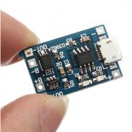
In this review we will talk about a very convenient board with a charge controller based on
TP4056. The board also has battery protection installed.
li-ion 3.7V.
Suitable for converting toys and household appliances from batteries to rechargeable batteries.
This is a cheap and efficient module that supports charging current up to 1A.
Briefly about adjusting the charging current for TP4056
Charge controller module TP4056 + battery protection S-8205A/B Series BATTERY PROTECTION IC
Provides protection against overcharge, overdischarge, triple protection against overload and short circuit.
Maximum charging current: 1A
Maximum continuous discharge current: 1A (peak 1.5A)
Charging voltage limitation: 4.275 V ±0. 025 V
Discharge limit (cut-off): 2.75 V ±0. 1 V
Battery protection, chip: DW01.
B+ connects to battery positive terminal
B- connects to the negative terminal of the battery
P- connects to the negative terminal of the load and charging connection point.
There is R3 on the board (marked 122 - 1.2 kOhm), to select the desired charging current for the element, select a resistor according to the table and resolder it.
Just in case, a typical inclusion of TP4056 from the specification.
This is not the first time that a lot of TP4056+BMS modules has been taken, and it turned out to be very
convenient for trouble-free alterations of household appliances and toys
batteries.
The modules are small in size, just smaller in width than two AA batteries,
flat - great for installing old batteries from
cell phones.
For charging, a standard 5V source from USB is used, the input is
MicroUSB The photo shows the minus and plus contacts on the sides of the MicroUSB
connector
There is nothing on the back side - this can help when attaching it with glue or tape.
MicroUSB connectors are used for power. Old boards on TP4056 had MiniUSB.
You can solder the boards together at the input and connect only one to USB -
in this way it is possible to charge 18650 cascades, for example, for
screwdrivers.
Outputs - extreme contact pads for connecting the load (OUT +/–),
in the middle BAT +/– to connect the battery cell.
The fee is small and convenient. Unlike just modules on TP4056, there is battery cell protection here.
The module is ideal for installation in various household appliances and
toys that are powered by 2-3-4-5 AA batteries or
AAA. Firstly, this brings some savings, especially with frequent
replacing batteries (in toys), and, secondly, convenience and versatility.
You can use batteries taken from old batteries for power supply.
from laptops, cell phones, disposable electronic cigarettes, etc.
Further. In case there are three elements, four, six and so on,
you need to use the StepUp module to increase the voltage from 3.7V to
4.5V/6.0V etc. Depending on the load, of course. Also convenient
option on two battery cells (2S, two boards in series,
7.4V) with StepDown board. Typically, StepDowns are adjustable, and
You can adjust any voltage within the supply voltage. This
extra space to accommodate AA/AAA batteries instead, but then you don’t have to
worry about the electronics of the toy.
Specifically, one of the boards was intended for the old IKEA
mixer. Very often it was necessary to replace the batteries in it, but
it worked poorly in batteries (in NiMH 1.2V instead of 1.5V). Everything for the motor
it doesn’t matter whether it will be powered by 3V or 3.7V, so I did without StepDown.
It even began to turn a little more vigorously.
Battery 08570 from an electronic cigarette is almost an ideal option
for any modifications (capacity is about 280 mAh, and the price is free).
But in this case it’s a bit long. The length of the AA battery is 50 mm, and
This battery is 57 mm, it won’t fit. You can, of course, make an “add-on”
for example, from polymorph plastic, but...
As a result, I took a small model battery with the same capacity. Very
it is advisable to reduce the charging current (up to 250...300 mA) by increasing the resistor
R3 on the board. You can heat the standard one, bend one end, and solder it
any available at 2-3 kOhm.
On the left is a picture of the old module. Placement on the new module
The components are different, but all the same elements are present. 
We connect the battery (Solder it) to the terminals in the middle BAT +/–,
unsolder the motor contacts from the contactor plates for AA batteries (their
remove it altogether), solder the motor load to the board output (OUT +/–).
You can cut a hole in the lid with a Dremel for USB.
I made a new lid - I completely threw out the old one. The new one has grooves for placing the board and a hole for MicroUSB.
As a battery for a mixer, it turns vigorously. Capacity 280mAh
enough for a few minutes of work, it takes 3-6 days to charge,
depending on how often you use it (I rarely use it, you can do it at once
plant if you get carried away). Due to the reduced charging current, it takes a long time to charge,
a little less than an hour. But any charging from a smartphone.
The TP4056 module with built-in BMS protection is very practical and versatile.
The module is designed for a charging current of 1A.
The module is convenient for remaking toys - radio-controlled cars,
robots, various lamps, remote controls... - all possible toys and
equipment where batteries have to be changed frequently.
Lithium batteries (Li-Io, Li-Po) are the most popular rechargeable sources of electrical energy at the moment. The lithium battery has a nominal voltage of 3.7 Volts, which is indicated on the case. However, a 100% charged battery has a voltage of 4.2 V, and a discharged one “to zero” has a voltage of 2.5 V. There is no point in discharging the battery below 3 V, firstly, it will deteriorate, and secondly, in the range from 3 to 2.5 It only supplies a couple of percent of energy to the battery. Thus, the operating voltage range is 3 – 4.2 Volts. You can watch my selection of tips for using and storing lithium batteries in this video
There are two options for connecting batteries, series and parallel.

With a series connection, the voltage on all batteries is summed up, when a load is connected, a current flows from each battery equal to the total current in the circuit; in general, the load resistance sets the discharge current. You should remember this from school. Now comes the fun part, capacity. The capacity of the assembly with this connection is fairly equal to the capacity of the battery with the smallest capacity. Let's imagine that all batteries are 100% charged. Look, the discharge current is the same everywhere, and the battery with the smallest capacity will be discharged first, this is at least logical. And as soon as it is discharged, it will no longer be possible to load this assembly. Yes, the remaining batteries are still charged. But if we continue to remove current, our weak battery will begin to overdischarge and fail. That is, it is correct to assume that the capacity of a series-connected assembly is equal to the capacity of the smallest or most discharged battery. From here we conclude: to assemble a series battery, firstly, you need to use batteries of equal capacity, and secondly, before assembly, they all must be charged equally, in other words, 100%. There is such a thing called BMS (Battery Monitoring System), it can monitor each battery in the battery, and as soon as one of them is discharged, it disconnects the entire battery from the load, this will be discussed below. Now as for charging such a battery. It must be charged with a voltage equal to the sum of the maximum voltages on all batteries. For lithium it is 4.2 volts. That is, we charge a battery of three with a voltage of 12.6 V. See what happens if the batteries are not the same. The battery with the smallest capacity will charge the fastest. But the rest have not yet charged. And our poor battery will fry and recharge until the rest are charged. Let me remind you that lithium also does not like overdischarge very much and deteriorates. To avoid this, recall the previous conclusion.
Let's move on to parallel connection. The capacity of such a battery is equal to the sum of the capacities of all batteries included in it. The discharge current for each cell is equal to the total load current divided by the number of cells. That is, the more Akum in such an assembly, the more current it can deliver. But an interesting thing happens with tension. If we collect batteries that have different voltages, that is, roughly speaking, charged to different percentages, then after connecting they will begin to exchange energy until the voltage on all cells becomes the same. We conclude: before assembly, the batteries must again be charged equally, otherwise large currents will flow during connection, and the discharged battery will be damaged, and most likely may even catch fire. During the discharge process, the batteries also exchange energy, that is, if one of the cans has a lower capacity, the others will not allow it to discharge faster than themselves, that is, in a parallel assembly you can use batteries with different capacities. The only exception is operation at high currents. On different batteries under load, the voltage drops differently, and current will start flowing between the “strong” and “weak” batteries, and we don’t need this at all. And the same goes for charging. You can absolutely safely charge batteries of different capacities in parallel, that is, balancing is not needed, the assembly will balance itself.
In both cases considered, the charging current and discharge current must be observed. The charging current for Li-Io should not exceed half the battery capacity in amperes (1000 mah battery - charge 0.5 A, 2 Ah battery, charge 1 A). The maximum discharge current is usually indicated in the datasheet (TTX) of the battery. For example: 18650 laptops and smartphone batteries cannot be loaded with a current exceeding 2 battery capacities in Amperes (example: a 2500 mah battery, which means the maximum you need to take from it is 2.5 * 2 = 5 Amps). But there are high-current batteries, where the discharge current is clearly indicated in the characteristics.
Features of charging batteries using Chinese modules
Standard purchased charging and protection module for 20 rubles for lithium battery ( link to Aliexpress)
(positioned by the seller as a module for one 18650 can) can and will charge any lithium battery, regardless of shape, size and capacity to the correct voltage of 4.2 volts (the voltage of a fully charged battery, to capacity). Even if it is a huge 8000mah lithium package (of course we are talking about one 3.6-3.7v cell). The module provides a charging current of 1 ampere, this means that they can safely charge any battery with a capacity of 2000mAh and above (2Ah, which means the charging current is half the capacity, 1A) and, accordingly, the charging time in hours will be equal to the battery capacity in amperes (in fact, a little more, one and a half to two hours for every 1000mah). By the way, the battery can be connected to the load while charging.

Important! If you want to charge a smaller capacity battery (for example, one old 900mAh can or a tiny 230mAh lithium pack), then the charging current of 1A is too much and should be reduced. This is done by replacing resistor R3 on the module according to the attached table. The resistor is not necessarily smd, the most ordinary one will do. Let me remind you that the charging current should be half the battery capacity (or less, no big deal).
But if the seller says that this module is for one 18650 can, can it charge two cans? Or three? What if you need to assemble a capacious power bank from several batteries?
CAN! All lithium batteries can be connected in parallel (all pluses to pluses, all minuses to minuses) REGARDLESS OF CAPACITY. Batteries soldered in parallel maintain an operating voltage of 4.2v and their capacity is added up. Even if you take one can at 3400mah and the second at 900, you will get 4300. The batteries will work as one unit and will discharge in proportion to their capacity.
The voltage in a PARALLEL assembly is ALWAYS THE SAME ON ALL BATTERIES! And not a single battery can physically discharge in the assembly before the others; the principle of communicating vessels works here. Those who claim the opposite and say that batteries with a lower capacity will discharge faster and die are confused with SERIAL assembly, spit in their faces. 
Important! Before connecting to each other, all batteries must have approximately the same voltage, so that at the time of soldering, equalizing currents do not flow between them; they can be very large. Therefore, it is best to simply charge each battery separately before assembly. Of course, the charging time of the entire assembly will increase, since you are using the same 1A module. But you can parallel two modules, obtaining a charging current of up to 2A (if your charger can provide that much). To do this, you need to connect all similar terminals of the modules with jumpers (except for Out- and B+, they are duplicated on the boards with other nickels and will already be connected anyway). Or you can buy a module ( link to Aliexpress), on which the microcircuits are already in parallel. This module is capable of charging with a current of 3 Amps.
Sorry for the obvious stuff, but people still get confused, so we'll have to discuss the difference between parallel and serial connections.
PARALLEL connection (all pluses to pluses, all minuses to minuses) maintains the battery voltage of 4.2 volts, but increases the capacity by adding all the capacities together. All power banks use parallel connection of several batteries. Such an assembly can still be charged from USB and the voltage is raised to an output of 5v by a boost converter.
CONSISTENT connection (each plus to minus of the subsequent battery) gives a multiple increase in the voltage of one charged bank 4.2V (2s - 8.4V, 3s - 12.6V and so on), but the capacity remains the same. If three 2000mah batteries are used, then the assembly capacity is 2000mah.
Important! It is believed that for sequential assembly it is strictly necessary to use only batteries of the same capacity. Actually this is not true. You can use different ones, but then the battery capacity will be determined by the SMALLEST capacity in the assembly. Add 3000+3000+800 and you get an 800mah assembly. Then the specialists begin to crow that the less capacious battery will then discharge faster and die. But it doesn’t matter! The main and truly sacred rule is that for sequential assembly it is always necessary to use a BMS protection board for the required number of cans. It will detect the voltage on each cell and turn off the entire assembly if one discharges first. In the case of an 800 bank, it will discharge, the BMS will disconnect the load from the battery, the discharge will stop and the residual charge of 2200mah on the remaining banks will no longer matter - you need to charge.
The BMS board, unlike a single charging module, IS NOT A sequential charger. Needed for charging configured source of the required voltage and current. Guyver made a video about this, so don’t waste your time, watch it, it’s about this in as much detail as possible.
Is it possible to charge a daisy chain assembly by connecting several single charging modules?
In fact, under certain assumptions, it is possible. For some homemade products, a scheme using single modules, also connected in series, has proven itself, but EACH module needs its own SEPARATE POWER SOURCE. If you charge 3s, take three phone chargers and connect each to one module. When using one source - power short circuit, nothing works. This system also works as protection for the assembly (but the modules are capable of delivering no more than 3 amperes). Or, simply charge the assembly one by one, connecting the module to each battery until fully charged.
Battery charge indicator 
Another pressing problem is to at least know approximately how much charge remains on the battery so that it does not run out at the most crucial moment.
For parallel 4.2-volt assemblies, the most obvious solution would be to immediately purchase a ready-made power bank board, which already has a display showing charge percentages. These percentages aren't super accurate, but they still help. The issue price is approximately 150-200 rubles, all are presented on the Guyver website. Even if you are not building a power bank but something else, this board is quite cheap and small to fit into a homemade product. Plus, it already has the function of charging and protecting batteries.
There are ready-made miniature indicators for one or several cans, 90-100 rubles  Well, the cheapest and most popular method is to use an MT3608 boost converter (30 rubles), set to 5-5.1v. Actually, if you make a power bank using any 5-volt converter, then you don’t even need to buy anything additional. The modification consists of installing a red or green LED (other colors will work at a different output voltage, from 6V and higher) through a 200-500 ohm current-limiting resistor between the output positive terminal (this will be a plus) and the input positive terminal (for an LED this will be a minus). You read that right, between two pluses! The fact is that when the converter operates, a voltage difference is created between the pluses; +4.2 and +5V give each other a voltage of 0.8V. When the battery is discharged, its voltage will drop, but the output from the converter is always stable, which means the difference will increase. And when the voltage on the bank is 3.2-3.4V, the difference will reach the required value to light the LED - it begins to show that it is time to charge.
How to measure battery capacity?

We are already accustomed to the idea that for measurements you need an Imax b6, but it costs money and is redundant for most radio amateurs. But there is a way to measure the capacity of a 1-2-3 can battery with sufficient accuracy and cheaply - a simple USB tester.
The whole story began with the fact that the Hame R1 pocket router I had just purchased (thanks to the review here, you can read it) died for a long time. More precisely, the charging chip has failed. How I dealt with this problem and ended up getting more functionality than it was originally, you can read under the cut.
Lots of photos, as well as fiddling around with a soldering iron.
If anything, I warned you =)
I apologize in advance for the unsightly quality of the photos.
Here we go!
After a week of use, the Hame R1 began to behave strangely: after the end of charging, the charging indicator was constantly on and 0.35A was constantly being consumed from the battery. An autopsy showed that this module was heating up: 
(soldered off and lying nearby))
A search on Google for the markings did not yield anything, but a quick poke at the pins of the microcircuit with probes made it clear that this was most likely the charging microcircuit.
This is where the subject, ordered in abundance from fasttech, came to the rescue. 
The device is simple and unpretentious. Based on the TP4056 microcircuit, which, by the way, is used to build the charging part of everyone’s favorite popular charger ml102 version 5.
The charge current is set by resistor R4; by default, a 1.2K Ohm resistor is soldered in, which corresponds to a charge current in CC of 1A.
If desired, for small-capacity batteries, the current can (and should!) be reduced. The ratio of current and required resistance can be found under the spoiler.
Additional Information
RPROG(k)IBAT (mA)
30 50
20 70
10 130
5 250
4 300
3 400
2 580
1.66 690
1.5 780
1.33 900
1.2 1000
There are two indicator LEDs on the subject. Red lights up during charging, and green lights up after charging is complete.
There is also a miniUSB connector on the board, so you can connect and use it, but not in our case. A board of this size simply will not fit into the router case.
So I opened Eagle and got to work.
Half an hour later, the device circuit was ready, and soon the track layout was ready:


I wired up a circuit without connectors or anything else. As compact as possible so that you can embed the device anywhere.
Next was LUT, etching, and applying a solder mask. For those interested, you can see a small photo report under the spoiler.
PCB overnight
We print the circuit on special Chinese paper, clean the textolite: 
After this, we transfer the toner to the textolite with an iron and etch it.
I etch in hydrogen peroxide. (100ml peroxide (50 degrees C) + 20g citric acid + 5g salt) 
While the board is etching, prepare a stencil for the solder mask. I don’t have a special film for printing, so I make do with laminating film. 
And here is the board etched: 


After applying the solder mask: 
Let's draw conclusions: 
And finally, let’s transfer the components from the subject to our board: 
Let's check the functionality: 

Everything is working!
Diagram for Eagle:
Well, the board is ready. Now there is another question. During testing, it turned out that with such a charging current, the microcircuit heats up quite a bit:

84gC after 2.5 minutes of work is PPC. When integrating a module into a device, you will have to take this into account.
We prepare the charging place above the RJ45 connector:

We solder to + I exit from the microUSB connector of the router

And also + from the battery, and ground (blue wire) near the reset button.

This is how I solved the overheating issue:


We install the module on the seat and secure it with hot glue:

For safety, we insert a special thermal pad between the heatsink and the microcircuit:

Apply thermal paste, install the radiator and glue it with superglue to the edge of the case (while pressing it down firmly)

Don't forget to make two holes in the case for charge indicators.

Last look before assembly:

That's all!
or…
Here are the final photos demonstrating the work: 

As you can see, the device has not lost its presentation, and most importantly, it has only gained functionality! Now, after charging is complete, the indicator doesn’t just stupidly go out, but the good green LED lights up.
That's all for sure now. If you have any questions, I will be happy to answer.
Beaver everyone! =)
UPD:
Thanks to user with nickname turbopascal007, it was found out what kind of chip was installed in my router. He was not lazy and disassembled his own, after which he sent me its markings. For EMC5755, Google produces a datasheet without any problems, unlike the C2C37 I have installed. So if anyone has the same problem, you can simply replace it.