Review of the MX50 SE radio constructor.
The best of the uncomplicated homemade mid-power ULFs?
You are interested? Then read the review!
Multi-review: amplifier, case, preamplifier, capacitors and more.
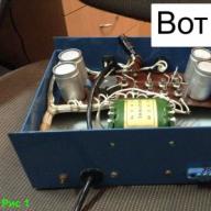
Foreword. Why did you assemble this ULF?
I had an idea to quickly assemble a simple compact ULF of not very high power. Originally planned to assemble ULF on LM1875 -. Acquired a Chinese whale as a basic test layout, body and transformer. After assembling the designer, it turned out that the ULF on this microcircuit at the limiting supply voltages cannot work normally at a load of 4 Ohms - the microcircuit heats up quickly, does not have time to give off heat to the radiator. And it turns off for thermal protection. It didn't suit me. Since the most expensive radio components (housing and transformer) were purchased, I decided to look for a circuit for another compact ULF. In the comments to the review comrade. Fizik and comrade .. html # comment2043615) recommended the subject. I decided to try to collect this ULF. It was in May. It's December now. ULF assembled :-)
Let's list the parameters of a good "folk" ULF
1. Must be cheap
2. Do not contain highly scarce parts
3. Easy to assemble and configure
4. Have enough power
5. Must play music well and have good characteristics.
LJM MX50 SE is a candidate for this title. The radio constructor can be bought for $ 12 on electronic platforms such as ebay and aliexpress. The usual price is about $ 15-16. I have listed another seller on ebay. The one who bought it from is not selling this product now.
Other variants of this whale
On Ali-ebee they sell soldered versions of this whale (cost $ 8-10) more expensive. There are whales with Saken 2SA1295 / 2SC3264 or 2SA1186 / 2SC2837 output transistors. They cost much more. The originality of the transistors cannot be verified. Therefore, it is better to buy a cheap whale, and then buy the transistors for the weekend in a trusted place and install on a debugged board.
The Chinese sell a variant of the MX100 (searched for by this name) - the same as the MX50 SE, but on one board: two channels, a power supply unit and acoustics protection from constant + power-on delay. 
They are sold in the form of a whale, an assembled board, or even an assembled ULF. Expensive sakens re-labeled KEC are also shoved into this version: 
If it were not for my situation with the finished case and the transformer, I would most likely buy a ready-made ULF and bring it to mind. How this can be done - see below. While working on this project, I did not know about the existence of the MX100.
They sell power transformers, stamps for connection, radiators for transistors, housings, etc. for this ULF
Equipment
A package came with a small bag, two boards and details:

There are no complaints about the quality of the one-sided PCB. Everything was done perfectly. Easily soldered. Everything is signed.


Output transistors South Korean KEC. Manufactured under license from Toshiba. Cost a penny. Accordingly, no one fakes them. The conclusions are not magnetised. 
Other radio parts, if anyone is interested


At the international forum, people noted the good quality of radio components for such a low price. Electrolytes "Rubicon", Philippine conventional capacitors and more. How can you check if it's true or not? Let's put our trust in the international community of radio amateurs. There are no superfluous details (we do not consider the transistor lining). They put everything that is indicated on the board.
Assembly
All this economy is assembled slowly in four to five hours. 
A transformer for 200-250 watts with two secondary windings for 18 V alternations (I, however, have a transformer with 4 secondary windings for 18 V - therefore there are two diode bridges). The power supply is a diode bridge and two electrolytes of 4700 uF at 50 V for each bus. The ULF power supply is bipolar. 26 Volts per bus after rectifier.
At the stand: 
Output transistors are installed through the pads on the radiator so that there is no direct contact between the metal plate and the radiator.
A properly assembled amplifier does not need tuning and starts working immediately when the load is connected and the signal is applied. But it's scary to turn it on right away. Therefore the standard checkout procedure. Instead of loading the output with a power resistor of 8 ohms, short-circuit the input. First switching on through a light bulb. If the light bulb flashed and immediately went out, nothing smoked or exploded, then everything is ok. Otherwise, the trouble is - check the installation, snot, transistors. Next, we check the power supply on the ULF board and the constant voltage between the ULF output and ground. Should be up to 30 mV. In my first version, everything was gorgeous on both channels: 

Disconnect the input shorted to the ground and the light bulb. If you are still afraid to connect speakers and give a signal, then we will use a sound generator and an oscilloscope. And let's apply a test signal to the input - sine 1 kHz: 
There should be an even, undistorted sinus. We get the maximum power Pmax \u003d 80 watts Prms \u003d 58 watts for a load of 8 ohms. With 26 V supply on one bus. Next comes clipping. A signal Vpp \u003d 1.6 V was applied to the input. At lower powers with a sine, everything is also ok at different frequencies.
Why do I indicate Vpp (voltage between max and min signal value) at the ULF input
Because such a signal shows my generator on its screen, and so it is convenient for me to debug when I look at its screen 
Let's feed a rectangle: 
Here, too, everything is gorgeous.
Now we connect (preferably through a constant-output protection circuit) the speaker and you can listen to music.
All these works on the assembly of the ULF and testing can be done in a weekend - hours in 6 free time. There is almost no ULF debugging. Everything works at once. Everything is ready? NO. The most not interesting begins - fine-tuning to the finished structure. This tweaking takes about 90% percent of the effort and time than assembling the circuit.
The first step is to choose a case for the ULF. Everything else is dictated by the corps. Homemade products start with the case, and then everything else - boards, power supplies, and so on.
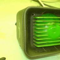
Housing
I had this case: 
Searched on ebay "Full Aluminum amplifier chassis amp Enclosure DAC Box 260 * 270 * 90mm L163-67"
It cost about 4800 rubles ($ 75) with delivery. The most expensive radio component.
External dimensions: width 260mm Height 90mm Depth 270mm
Internal dimensions: Width 250mm Height 80mm Depth 205mm 
The set includes accessories for assembly, legs, a power block, an input switching button, a volume control knob, a power button. There are no RCA and speaker connectors.
Came disassembled. Well packed. Going fine. Not crooked. The holes are all in place. Everything is neatly painted. There is no trace of the slightest scratch. Strong enough paint. The set includes boards for switching inputs to relays (fixed directly to the input sockets) and a board for controlling this switch on a microcircuit (12 V AC power). 

The area of \u200b\u200bone side radiator is 2.5 * 2 * 55 * 9 + 25 * 2 * 9 ~ 2900 cm ^ 2. Substrate thickness 6 mm.
Cons of the case:
1. Weak power button SW-3. In case of careless assembly, it can break. It is better to buy on Ali SPTA - "AC 250V 2A / 8A Latching SPST Push Button Power 2Pin Switch SW-3 Switches"
2. The channel selector does not remember the enabled input when the power is turned off. The main entrance is always included.
3. Since the relay unit is soldered directly onto the connectors, a complex circuit is obtained.
4. There are no ventilation holes on the bottom of the case. Only from above.
5. In order for all parts of the case to be connected together, you need to clean the paint - otherwise the parts of the case will not ring out and will not form a screen.
6. When I finally assembled the ULF, I found that if a signal source is not connected to the input or there is no plug on the ground in the connector, then when switching to this input at maximum volume, the signal from another input is very quietly heard (of course, if it is there). I sin on wiring the ground on the input RCA connectors - I soldered them all together and connected them to the selector board. Perhaps it was better to pull individual wires from each RCA jack to the volume control or common ground? If someone knows the reason - tell me.
Power for ULF
Power transformer
As you know, the power and quality of the ULF is determined by its power supply. Power transformer and power supply.
Power transformer - 200-250 VA total power (Watt) for two channels (stereo). Primary - 220 V. Two secondary windings. The food is bipolar. Secondary depends on the load. The developer of this kit appears on the international forum under the nickname LJM_LJM. He advises the following secondary voltages for acoustic impedance:
2 Ohm - 12 V AC voltage - after rectifier about 17 V
4 Ohm - 18 V AC - after rectifier about 26 V
8 Ohm - 25 V AC - after rectifier about 35 V
Naturally, acoustics of higher impedance can be connected to the ULF with less power. The power will decrease. If you connect the 4 Ohm acoustics to the 35V power supply option, then this experiment will lead to the failure of the KEC B817 / D1047 output transistors. Other transistors need to be installed there. It is also not recommended to raise the power supply above 35V. Failure of transistors, deterioration of parameters, recalculation of the circuit, change of circuitry ... People from the international forum tortured the circuit in the simulator and admitted that the parts from the set were the optimal circuit. By parameters, circuitry, details, price. LJM_LJM wrote that if you need more power, buy another kit.
I decided to stop at a 250 W transformer with 18 V secondary power supply. We get 4 Ohm ULF (max 100 W) or 8 Ohm (max 60 W). In ChiD there was such a troid trance "Torel TTP250 (2x2x18V, 3.5A), Toroidal transformer, 2x2x18V, 3.5A" - I bought it for 2300 rubles. Four secondary windings will allow you to either make "double mono" or use two windings on each arm using a full-wave rectifier. During the experiments I made two circuits, but in the end I settled on the "double mono" option - a separate power supply unit per channel.
There is a silicone insulating gasket between the transformer and the housing. Since I have a power supply on top of the transformer, I also insulated it with the same gasket on top.
At the end of the assembly, the transformer from Torel revealed such a feature - it hums a little if it plugs into an outlet in one of the rooms of the apartment. Humming slightly even without load. With load, it buzzes the same way. In a closed case, you can hardly hear it. In the room where the ULF was debugged, everything was ok. Different wires from the meter at the entrance to the apartment go to different rooms. I sin on the quality of the wiring in the apartment, the power supply in the network and the quality of the transformer from Torel. Just in case, I ordered another one for a replacement. When it comes, I'll try to test it first. If everything is ok, I will replace it. The first time I encountered this.
Power Supply
Standard rectifier and filter capacitors. 
Diode bridges are assembled on Schottky diodes MBR20100CT. I installed them on small radiators. Even at full load, they do not heat up. Filter capacitors - Nichicon Elko Low ESR 35V 4700 uF. Normal, not for audio. Borrowed from Germany on ebay. Two per shoulder. Only 8 pieces. The total capacity is 37600 uF.
Shunting SMD ceramics 0.1 μF. Soldered directly to the capacitor leads. Resistors for capacitor discharge - 2 watts 4.7 kOhm. 2A fuses. I screwed up a bit - the power indication diodes on the buses had to be installed after the fuses. Installed before. Didn't change it. Then I added a 5-watt 0.68 Ohm resistor between the filter capacitors to reduce ripple (CRC filter) - but I decided to abandon them - I short-circuited it. They did not affect the level of the ULF background. I made a signet with LUT: 

The 220 V power supply has a 2A fuse. I did not install the soft start. The fuse does not blow out from the charge of the capacitor bank when turned on. I also installed a 10A EMI filter after the power switch in front of the transformers - searched on ebay according to the words "250VAC 10A Power Line EMI Filter Three Lines Metal Housing EMI Filter CW1B-10A-L"
AC DC voltage protection and power-on delay
I used such a kit from ebay - "UPC1237 Speaker Protection Board DIY KIT Used Japan OMRON Relay for Dual Channel" worth about $ 10 
I chose protection based on the size. Now I think it was better to make two separate defenses myself for double mono. The protection turned out to be not very convenient - there is no LED to indicate the actuation state and the power indication LED. I slightly modified it by adding the Mute function (temporary mute) - I soldered the toggle switch (brought it to the front panel) into the break of the track from the 7th output of the UPC1237 microcircuit or fed the first leg through the toggle switch from the stub on the protection board - I don't remember how I did it now.
Protection power supply - separate 12V transformer. One secondary winding of this transformer is used to protect the AC, the second is used to power the input switching module.
The protection is triggered when a 2V DC appears at the input: 
ULF circuitry. UPGRATE
The Chinese took the ULF circuitry from
... They changed it a little unprincipledly and used inexpensive parts, developed a printed circuit board.
This is a B-class power amplifier. The quiescent current is set by the resistor R17.
I will write about possible upgrades. I took ideas from the international forum and from the article by Jake Rothman "MX50 power amplifier kit - Part-1 / Part-2" Everyday Practical Electronics 2017 number 5 and number 6.
Useful upgrades
1. From the kit, replace the input capacitor with something more decent with a capacity of 1 to 4.7 μF. There is a place for a large capacitor. You can try films like Wima MKP, non-polar electrolytes, and more. I tried different options that I had. Most of all, I liked the sound with non-polar electrolytes Nichicon BP-S-GB 2,2uF 50V. I bought it in Switzerland on Ebay.
2. C2 installed Wima 330pF film. With the recommended capacitance of 470pF, it felt like too much bass.
3. Install a Bush circuit - a resistor and an inductor - an enameled wire on the frame, wound on a 2 W 4.7 Ohm resistor on the ULF output. Solder the terminals of the coil to the terminals of the resistor and install in the break of the ULF output. 
Neutral Upgrades - That Didn't Benefit
1. I changed the rest of the usual capacitors for high quality ones - Wima. I did not notice any changes in sound and measurements. Left those that were in the whale.
2. Replacement of output transistors. I put the original Sanken 2sa1186 / 2sc2837 and Toshiba 2Sa1943 / 2Sc5200 (suspicion of a high-quality fake) - I did not notice any changes in the sound. Left KEC B817 / D1047 - the point is to spend money and look for originals, if it works well with the stock.
3. I changed T9 to 2SC3071 following the advice from the Everyday Practical Electronics article. I did not notice any changes. The constant at the output has increased to 40 mV.
Harmful upgrades
1. In the article Everyday Practical Electronics, it is suggested to solder a resistor on the fuses in the PSU - so that it smokes in case the fuse blows 
It's hard to solder on the fuse, and then on each new one, if it burns out. He sticks out from above. Not always convenient. It is better to put LEDs after the fuses.
2. In the article Everyday Practical Electronics they propose to install short-circuit protection at the ULF output: 
I implemented this protection as a surcharge, which is attached above the output transistors to the holes for attaching the amplifier board: 
Protection works - I tried to short-circuit the output. Disconnected. We remove the short circuit - everything is playing further, as if nothing had happened. But from this protection the background level increased sharply.
Without protection: 

With protection: 

The background is audible from behind the speakers, even at low volume during pauses in music. At first I thought it was due to the power supply, ground or wiring. No - it was this very protection. The background was independent of the location of the amplifier board. For this reason, I decided not to install this protection.
3. Preamplifier. Suddenly you need a preamplifier for this ULF. Such a preamplifier is recommended - it is searched for on Ali according to the words "Mini P7 preamp Board for MX50":  I similar put together c:
With a resistor, which is 22kOhm, you can adjust the gain of this pre. I did it 3 times. I don’t remember which resistor was soldered there. I planned to first build it into the ULF. Powered by the first version of the PSU (common power supply for two channels). On the "family" photo of the first version of the power supply amplifier (center) and before (lower left corner): 
In that version, there was one power supply unit for two channels. It was powered from the main buses through linear stabilizers for 12V. As a result, the ULF began to self-excite (sine distortion - twitching sine) and after a while the output transistors burned out. From external power supply - everything is ok. Conclusion - if you need a pre - then a separate transformer or winding on the main trance for him. I didn't have room for a third transformer, so I did it without a pre. If I do something external - for example, this
Assembly
ULF modules assembled according to the following scheme: 
All signal cables are screened. The screens are connected to the body. Volume control - ALPS 50kOhm RK27. Power supply of the amplifier and connection of acoustic systems - with an acoustic cable with a cross section of 1.5 mm ^ 2. The speaker ground is connected to the amplifier boards, not to the speaker protection module. Speaker protection has a common ground for two channels - the signals are mixed and the stereo effect is lost. So I connected it this way. 
Other photos without top cover


This amplifier turned out in the case:

Other photos


We weigh:

Compared to the 430mm Hi-Fi body:

Measurements
Let's measure the quiescent current.
Immediately after switching on. Resistor in the open circuit of the power supply 0.5 Ohm. Quiescent current according to Ohm's law \u003d 40.8 mA: 
In 20 minutes. Quiescent current according to Ohm's law \u003d 36.8 mA: 
The amplifier enters the clipping with an input signal of 1.6 V (between the maximum and minimum signal).
Standard signals. The load is an 8 ohm resistor. 1 kHz.
Sine (input signal 1.5 V between max and min signal): 

Let's calculate the power. Pmax \u003d 54 watts. P rms \u003d 27 watts.
Rectangle: 
Triangle: 
Distortion of the "step" type is not observed at different powers and frequencies.
Measurements in the RMAA program were made at a power of Pmax \u003d 34.5 W, P rms \u003d 17.25 W. At high powers, distortions begin in the spectrum. At less, they decrease. 


Sound rating
There is no background. More precisely, at maximum volume with the inputs shorted to ground, the background of about 100 Hz ceases to be audible 10 cm from the speaker. No cell phone interference. The ULF "warm-up" time is about 20-30 minutes. At maximum volume in an hour, my radiators heat up to 30 degrees - you can keep your hand on them. On a small usual one - cold. The sound is clear. Bass, high - everything is normal. The sound is clear and transparent. On my main bookshelf speakers Mission M51 plays fine. On the AEG LB 4720 speakers, the low ones hammer hard, like a hammer. However, other amplifiers (except JLH1969) have the same effect. Compared to other ULFs, it plays (subjectively) better than amplifiers on TDA2030 / TDA2050 / LM1875 (), LM3886 (), TDA7294 () microcircuits. JLH1969 () plays more pleasant and "more detailed", "warmer". The Naim NAP250 clone is sharper, stiffer and more dynamic. All assessments are subjective :-)
Overall score
For 5 characteristics of a good "folk" ULF, this circuit is excellent. This is how it is characterized by all who repeated it. There is enough power to sound the room. Also on the basis (due to the compactness of boards, small radiators) it is assembled by radio amateurs for embedding inside acoustics, multichannel amplifiers or receivers.
+137
+235
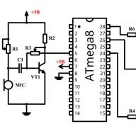
In this article I will tell you about such a microcircuit as TDA1514A
Introduction
I'll start a little with a sad one ... At the moment, the production of the microcircuit is discontinued ... But this does not mean that it is now "worth its weight in gold", no. You can get it at almost any radio store or on the radio market at a price of 100 - 500 rubles. Agree, a little expensive, but the price is absolutely fair! By the way, on world Internet sites such as they are much cheaper ...
The microcircuit has low distortion and a wide range of reproducible frequencies, therefore it is better to use it on full-range speakers. People who assembled amplifiers on this microcircuit praise it for its high sound quality. This is one of the few microcircuits that really "sound quality". The sound quality is not nearly inferior to the now popular TDA7293 / 94. However, if errors are made in the assembly, quality work is not guaranteed.
Brief description and advantages
This microcircuit is a single-channel Hi-Fi amplifier of class AB, the power of which is 50W. The microcircuit has built-in SOAR protection, thermal protection (overheating protection) and "Mute" mode
The advantages include the absence of clicks when turning on and off, the presence of protections, low harmonic and intermodulation distortion, low thermal resistance, and more. There is practically nothing to single out from the shortcomings, except for failure with a "running" voltage (the power supply should be more or less stable) and a relatively high price
Briefly about the appearance
The microcircuit is produced in a SIP package with 9 long legs. The leg pitch is 2.54mm. On the front side there are inscriptions and a logo, and on the back there is a heatsink - it is connected to the 4th leg, and the 4th leg is "-" the power supply. On the sides there are 2 lugs for attaching a radiator.

The original or a fake?
Many people are asking this question, I will try to answer you.
So. The microcircuit must be neatly made, the legs must be smooth, slight deformation is allowed, since it is not known how they were treated in a warehouse or store
Inscription ... It can be made either with white paint or with a conventional laser, two microcircuits above for comparison (both original). In the event that the inscription is applied with paint, there should ALWAYS be a vertical strip on the microcircuit, separated by an eyelet. Don't be confused by the inscription "TAIWAN" - it's okay, the sound quality of such copies is not nearly worse than those without this inscription. By the way, almost half of the radio components are made in Taiwan and neighboring countries. This inscription is not found on all microcircuits.
I also advise you to pay attention to the second line. If it contains only numbers (there should be 5 of them), these are chips of "old" production. The inscription on them is wider, and the heat sink may also have a different shape. If the inscription on the microcircuit is applied with a laser and the second line contains only 5 digits, there must be a vertical stripe on the microcircuit
The logo on the microcircuit must be present and only "PHILIPS"! As far as I know, production stopped long before the founding of NXP, and this is 2006. If you come across this microcircuit with the NXP logo, then one of two things - the microcircuit has started to be produced again, or a typical "left"
It also requires the presence of depressions in the form of circles, as in the photo. If they are not there, it is a fake.
Perhaps there are still ways to identify the "left", but do not strain so much over this issue. There are only a few cases of marriage.
Microcircuit specifications
* Input impedance and gain is adjusted by external elements
Below is a table of approximate output powers depending on power supply and load resistance
| Supply voltage | Load resistance | ||
| 4 ohm | 8 ohm | ||
| 10W | 6W | ||
| + -16.5V |
28W |
12W | |
| 48W | 28W | ||
| 58W | 32W | ||
| 69W | 40W | ||
Schematic diagram
The scheme is taken from the datasheet (May 1992)

It is too cumbersome ... I had to redraw:

The circuit is slightly different from the one provided by the manufacturer, all the characteristics given above are exactly for THIS circuit. There are several differences and all of them are aimed at improving the sound - first of all, filtering capacities are installed, the "voltage boost" is removed (about it a little later) and the value of the resistor R6 is changed.
Now in more detail about each component. C1 - input blocking capacitor. It passes through itself only the alternating voltage of the signal. It also affects the frequency response - the smaller the capacitance, the less LF and, accordingly, the larger the capacitance, the more LF. I would not recommend putting more than 4.7 mkF, since the manufacturer has provided for everything - with the capacity of this capacitor equal to 1 mkF, the amplifier reproduces the declared frequencies. Use a film capacitor, in extreme cases electrolytic (non-polar is desirable), but not ceramic! R1 reduces the input impedance, and together with C2 forms an input noise filter.
As with any operational amplifier, you can set the gain here. This is done with R2 and R7. At these ratings, the KU is 30 dB (may deviate slightly). C4 affects the activation of the SOAR and Mute protection, R5 affects the smooth charging and discharging of the capacitor, and therefore there are no clicks when the amplifier is turned on and off. C5 and R6 form the so-called Zobel chain. Its task is to prevent self-excitation of the amplifier, as well as to stabilize the frequency response. C6-C10 suppress power ripple, protect against voltage drop.
Resistors in this circuit can be taken with any power, for example, I use the standard 0.25W. Capacitors for a voltage of at least 35V, except for C10 - I use 100V in my circuit, although 63V should be enough. All components must be checked for serviceability before soldering!
Amplifier circuit with "voltage boost"

This version of the circuit is taken from the datasheet. It differs from the above-described scheme by the presence of elements C3, R3 and R4.
This option will allow you to get up to 4W more than stated (at ± 23V). But with this inclusion, distortion may slightly increase. Use resistors R3 and R4 at 0.25W. They could not stand it at 0.125W. Capacitor C3 - 35V and higher.

This circuit requires the use of two microcircuits. One gives a positive signal at the output, the other negative. With this inclusion, more than 100W can be removed at 8 ohms.
According to those who gathered, this circuit is absolutely workable and I even have a more detailed table of approximate output powers. She is below:
And if you experiment, for example, connect a load of 4 ohms at ± 23V, you can get up to 200W! Provided that the radiators do not get too hot, 150W will easily be pulled into the microcircuit bridge.
This design is good for subwoofers.
Work in external output transistors
The microcircuit is essentially a powerful operational amplifier and it can be further enhanced by hanging a pair of complementary transistors at the output. This option has not yet been tested, but theoretically it is possible. You can also power up the bridge circuit of the amplifier by hanging a pair of complementary transistors at the output of each microcircuit
Operation with unipolar power supply
At the very beginning of the datasheet, I found lines in which it is written that the microcircuit also works with unipolar power. And where is the circuit then? Alas, there is no datasheet, I didn’t find it on the Internet ... I don’t know, maybe there is such a scheme somewhere, but I haven’t seen this one ... The only thing I can advise is TDA1512 or TDA1520. The sound is great, but they are powered by a unipolar power supply, and the output capacitor can slightly spoil the picture. Finding them is quite problematic, they were produced a very long time ago and were long ago discontinued. The inscriptions on them can be of various shapes, it is not worth checking them for "fake" - there were no cases of refusal.
Both microcircuits are Hi-Fi - class AB amplifiers. Power is about 20W at + 33V into a load of 4 ohms. I will not give the diagrams (the topic is still about TDA1514A). You can download printed circuit boards for them at the end of the article.
Food
For stable operation of the microcircuit, a power supply with a voltage of ± 8 to ± 30V with a current of at least 1.5A is needed. Power should be supplied with thick wires, remove input wires as far as possible from output wires and power source
You can feed with an ordinary simple power supply, which includes a mains transformer, a diode bridge, filter capacities and, if desired, chokes. To obtain ± 24V, a transformer with two secondary windings of 18V each with a current of more than 1.5A for one microcircuit is required.
You can use switching power supplies, for example the simplest one, on the IR2153. Here is its diagram:

This UPS is a half-bridge, 47kHz (set with R4 and C4). Diodes VD3-VD6 ultrafast or Schottky
It is possible to use this amplifier in a car using a boost converter. On the same IR2153, here is the diagram:

The converter is made according to the Push-Pull scheme. Frequency 47kHz. Rectifier diodes are needed ultrafast or Schottky. The transformer calculation can also be done in ExcellentIT. Chokes in both circuits will be "advised" by ExcellentIT itself. They should be counted in the Drossel program. The author of the program is the same -
I want to say a few words about the IR2153 - the power supplies and converters are pretty good, but the microcircuit does not provide for stabilization of the output voltage and therefore it will change depending on the supply voltage, and it will sink.
It is not necessary to use IR2153 and switching power supplies in general. You can do it easier - as in the "old days", a conventional transformer with a diode bridge and huge power supply capacities. This is how his scheme looks like:

C1 and C4 not less than 4700μF, for voltage not less than 35V. C2 and C3 - ceramics or film.
Printed circuit boards
I now have a collection of boards like this:
a) the main one - it can be seen in the photo below.
b) slightly modified first (main). All the tracks are increased in width, the power tracks are much wider, the elements are slightly moved.
c) bridge circuit. The board is not drawn very well, but it is functional
d) the first version of the PP - the first trial version, the Zobel chain is not enough, and so it was assembled, it works. There is even a photo (below)
e) printed circuit board fromXandR_man - found on the site forum "Soldering iron". What can I say ... Strictly a diagram from a datasheet. Moreover, I have seen kits based on this signet with my own eyes!
In addition, you can draw the board yourself if you are not satisfied with the ones provided.
Soldering
After you have made the board and checked all the parts for serviceability, you can start soldering.
Tin the entire board, and tin the power tracks with as thick a layer of solder as possible
All the jumpers are soldered first (their thickness should be as large as possible in the power sections), and then all the components to increase in size. the microcircuit is soldered last. I advise you not to cut the legs, but to solder it as it is. You can then bend it for easy fit onto the radiator.
The microcircuit is protected from static electricity, so you can solder with the included soldering iron, even while sitting in woolen clothes.
However, it is necessary to solder so that the microcircuit does not overheat. For reliability, it can be attached to the radiator by one eyelet during soldering. It is possible for two, there will be no difference here, as long as the crystal inside does not overheat.
Setup and first launch
After all the elements and wires are soldered, a "test run" is required. Screw the microcircuit onto the radiator, short-circuit the input wire to ground. As a load, you can connect future speakers, but in general, so that they do not "fly out" in a fraction of a second in case of marriage or installation errors, use a powerful resistor as a load. If it crashes, you should know - you made a mistake, or you got a defect (the microcircuit is meant). Fortunately, such cases almost never occur, unlike the TDA7293 and others, which in the store you can collect a bunch from one batch and as it turns out later, they are all defective.
However, I want to make a small comment. Keep your wires as short as possible. It was such that I just lengthened the output wires and began to hear a hum in the speakers, similar to a "constant". Moreover, when the amplifier was turned on, due to the "constant", the speaker produced a hum that disappeared after 1-2 seconds. Now I have wires coming out of the board, a maximum of 25 cm and go directly to the speaker - the amplifier turns on silently and works without problems! Pay attention to the input wires too - put a shielded wire, you shouldn't make it long either. Follow simple requirements and you will succeed!
If nothing happens to the resistor, turn off the power, attach the input wires to the signal source, connect your speakers and apply power. A small background can be heard in the speakers - this indicates that the amplifier is working! Give a signal and enjoy the sound (if everything is perfectly assembled). If "grunts", "fart" - look at the food, at the correct assembly, because as revealed in practice, there are no such "nasty" specimens, which, with proper assembly and excellent nutrition, worked crookedly ...
What the finished amplifier looks like
Here is a series of photos taken in December 2012. The boards just after soldering. Then I collected to make sure that the microcircuits were working.


But my first amplifier, only the board has survived to this day, all the details went to other circuits, and the microcircuit itself failed due to an AC voltage hitting it


Below are fresh photos:


Unfortunately, my UPS is at the manufacturing stage, and I powered the microcircuit earlier from two identical batteries and a small transformer with a diode bridge and small power capacities, in the end it was± 25V. Two such microcircuits with four speakers from the "Sharp" music center played in such a way that even objects on the tables "danced to the music", the windows rang, and the body felt the power quite well. I can't take it off now, but there is a ± 16V power supply, from it you can get up to 20W at 4 ohms ... Here is a video to you as proof that the amplifier is absolutely working!
Acknowledgments
I express my deep gratitude to the users of the Soldering Iron website forum, and specifically, a huge thank you to the user for some help, I also thank many others (sorry for not calling you by nicknames) for honest reviews that prompted me to assemble this amplifier. Without all of you, this article might not have been written.
Completion
The microcircuit has a number of advantages, excellent sounding first of all. Many microcircuits of this class may even be inferior in sound quality, but this depends on the quality of the assembly. Bad build, bad sound. Take electronic circuit assembly seriously. I highly do not recommend soldering this amplifier with surface mounting - this can only worsen the sound, or lead to self-excitation, and subsequently complete failure.
I collected almost all the information that I checked myself and could ask other people who collected this amplifier. It is a pity that I do not have an oscilloscope - without it my statements about the sound quality do not mean anything ... But I will continue to argue that it sounds just fine! Those who collected this amplifier will understand me!
If you have any questions, write to me on the forum of the Soldering Iron website. on the discussion of amplifiers on this microcircuit, you can ask there.
I hope the article was useful for you. Good luck to you! Regards, Yuri.
List of radioelements
| Designation | A type | Denomination | amount | Note | Score | My notebook | |
|---|---|---|---|---|---|---|---|
| Chip | TDA1514A | 1 | Into notepad | ||||
| C1 | Capacitor | 1 uF | 1 | Into notepad | |||
| C2 | Capacitor | 220 pF | 1 | Into notepad | |||
| C4 | 3.3μF | 1 | Into notepad | ||||
| C5 | Capacitor | 22 nF | 1 | Into notepad | |||
| C6, C8 | Electrolytic capacitor | 1000μF | 2 | Into notepad | |||
| C7, C9 | Capacitor | 470 nF | 2 | Into notepad | |||
| C10 | Electrolytic capacitor | 100μF | 1 | 100V | Into notepad | ||
| R1 | Resistor | 20 kΩ | 1 | Into notepad | |||
| R2 | Resistor | 680 Ohm | 1 | Into notepad | |||
| R5 | Resistor | 470 k Ohm | 1 | Into notepad | |||
| R6 | Resistor | 10 ohm | 1 | Selected when setting up | Into notepad | ||
| R7 | Resistor | 22 k Ohm | 1 | Into notepad | |||
| Booster circuit | |||||||
| Chip | TDA1514A | 1 | Into notepad | ||||
| C1 | Capacitor | 1 uF | 1 | Into notepad | |||
| C2 | Capacitor | 220 pF | 1 | Into notepad | |||
| C3 | Electrolytic capacitor | 220μF | 1 | 35V and above | Into notepad | ||
| C4 | Electrolytic capacitor | 3.3μF | 1 | Into notepad | |||
| C5 | Capacitor | 22 nF | 1 | Into notepad | |||
| C6, C8 | Electrolytic capacitor | 1000μF | 2 | Into notepad | |||
| C7, C9 | Capacitor | 470 nF | 2 | Into notepad | |||
| C10 | Electrolytic capacitor | 100μF | 1 | 100V | Into notepad | ||
| R1 | Resistor | 20 kΩ | 1 | Into notepad | |||
| R2 | Resistor | 680 Ohm | 1 | Into notepad | |||
| R3 | Resistor | 47 Ohm | 1 | Selected when setting up | Into notepad | ||
| R4 | Resistor | 82 Ohm | 1 | Selected when setting up | Into notepad | ||
| R5 | Resistor | 470 k Ohm | 1 | Into notepad | |||
| R6 | Resistor | 10 ohm | 1 | Selected when setting up | Into notepad | ||
| R7 | Resistor | 22 k Ohm | 1 | Into notepad | |||
| Bridge inclusion | |||||||
| Chip | TDA1514A | 2 | Into notepad | ||||
| C1 | Capacitor | 1 uF | 1 | Into notepad | |||
| C2 | Capacitor | 220 pF | 1 | Into notepad | |||
| C4 | Electrolytic capacitor | 3.3μF | 1 | Into notepad | |||
| C5, C14, C16 | Capacitor | 22 nF | 3 | Into notepad | |||
| C6, C8 | Electrolytic capacitor | 1000μF | 2 | Into notepad | |||
| C7, C9 | Capacitor | 470 nF | 2 | Into notepad | |||
| C13, C15 | Electrolytic capacitor | 3.3μF | 2 | Into notepad | |||
| R1, R7 | Resistor | 20 kΩ | 2 | Into notepad | |||
| R2, R8 | Resistor | 680 Ohm | 2 | Into notepad | |||
| R5, R9 | Resistor | 470 k Ohm | 2 | Into notepad | |||
| R6, R10 | Resistor | 10 ohm | 2 | Selected when setting | Into notepad | ||
| R11 | Resistor | 1.3 k Ohm | 1 | Into notepad | |||
| R12, R13 | Resistor | 22 k Ohm | 2 | Into notepad | |||
| Impulse power block | |||||||
| IC1 | Power driver and MOSFET | IR2153 | 1 | Into notepad | |||
| VT1, VT2 | MOSFET transistor | IRF740 | 2 | Into notepad | |||
| VD1, VD2 | Rectifier diode | SF18 | 2 | Into notepad | |||
| VD3-VD6 | Diode | Any Schottky | 4 | Ultrafast diodes or Schottky | Into notepad | ||
| VDS1 | Diode bridge | 1 | Diode bridge for the required current | Into notepad | |||
| C1, C2 | Electrolytic capacitor | 680μF | 2 | 200V | Into notepad | ||
| C3 | Capacitor | 10 nF | 1 | 400V | Into notepad | ||
| C4 | Capacitor | 1000 pF | 1 | Into notepad | |||
| C5 | Electrolytic capacitor | 100μF | 1 | Into notepad | |||
| C6 | Capacitor | 470 nF | 1 | Into notepad | |||
| C7 | Capacitor | 1 nF | 1 | ||||
The bass amplifier is assembled on a TPA3116D2 microcircuit.
Specifications.
Power into a load of 4 ohms. at U pit. 21B. - 2 x 50 W. (BTL), 100 W. (PBTL)
Input signal level. - 0.8 ... 2V.
Signal to noise ratio. - 102 dB
Harmonic distortion at half power 25W. - 0.1%
Supply voltage - 4.5 V ... 26 V.
The circuit allows you to turn on the microcircuit in two modes:
1. Bridge BTL. In this inclusion, you can get 2 channels of 50 watts.
2. Parallel pavement (PBTL). Since in this mode two BTL channels are also connected in parallel, at the output we get one channel with twice the power - 100 W.
The diagrams below show all the necessary changes for both modes.
1. Preparing the board for work in bridge mode. Stereo 50W.
The assembled amplifier operates in bridged mode. But if you send a signal to it on an unbalanced line, set jumpers P7 and P12. No more jumpers are required.
2. Preparing the board for operation in parallel-bridge mode. One channel 100 watts.
Set jumpers P14, P15 and jumper the amplifier outputs P3 to P4 and P8 to P11.
Your amplifier will now operate in parallel-bridged mode and deliver 100 watts. Connect the loudspeaker to P6 and P8. Apply the signal to the input of the right channel.


By selecting resistors R5 and R8, you can select the gain level and input resistance, as well as switch the amplifier to the master or slave modes

The amplifier has a very high efficiency\u003e 90%, so it is not very demanding on the heat sink. As a radiator, you can use, for example, this one. Shape, mounting holes and dimensions, which are made especially for this module. In addition, it has a gold plating, which looks very attractive.
Radiator

This is an open source project! The license under which it is distributed -
When building a high-quality ULF, many people choose the well-proven specialized microcircuit LM3886 - a high-quality audio power amplifier capable of delivering more than 50 watts of continuous average power into a 4-ohm load and 40 watts into 8 ohms, at 0.1% THD + N, in a frequency range from 20 Hz to 20 kHz. Why LM3886? It has fully protected elements at the output from overvoltage, undervoltage, overloads, including instantaneous temperature peaks. Thermal protection is triggered faster than the chip is destroyed. It has an excellent signal-to-noise ratio of more than 92 dB, with a low noise level of only 2 μV. It exhibits extremely low THD + N, around 0.03% at nominal audio power, and provides excellent linearity.
50 watt sound amplifier circuit
In fact, the circuit is similar to the one that. The divider Rf1, Ri determine the gain in this case, the gain is 22k / 1k \u003d 22 (27dB). The Ci 47uF capacitor forms a high-pass filter with a cut-off frequency of 5 Hz.
Amplifier characteristics on LM3886
- Maximum Output Power: 65W RMS - 108W Peak
- Total Harmonic Distortion: 0.02% @ 50W
- Signal-to-noise ratio: 110dB @ 50W - 92dB @ 1W

LM3886 has the following protection systems:
- overvoltage;
- overload;
- from short circuit of the output;
- from overheating.

Another feature of the circuit is the absence of a delay time capacitor that is connected to the MUTE. Coil L1 contains 15 turns of enameled wire around resistor R7. The wire diameter must be at least 0.5 mm. The entire choke structure is wrapped in heat shrink tubing. Capacitor C2 can be electrolytic, but non-polar or bipolar is better.

As a rule, in audio amplifiers, toroidal transformers are used small in size, but such transformers are expensive and scarce. The advantage of a toroidal transformer is that they have very low flux leakage, so they can be housed in the same package as the amplifier. In this project we use a standard transformer. The characteristics of the transformer should be as follows;
- For 8 Ohms - standard mode: 220/2 x 24 V (with medium output) at least 150 W
- For 4 Ohms - standard mode: 220/2 x 18 V (with medium output) at least 150 W

The power supply is simple - a bridge rectifier and 4 x 10,000uF / 50V capacitors. The IC can be mounted on a heatsink without insulation for better thermal conductivity, but then it must be insulated from the metal case, which is usually connected to ground. The archive is.
The design of this D-class sound amplifier was created for experiment (I have long wanted to listen to and evaluate the new D-class), in addition, a new audio amplifier was needed to replace the old one for a computer. It was decided to buy 2 ready-made bridge amplifier modules in class D which are called TPA3118 (like the microcircuit that is installed in them). They cost 150 rubles each and theoretically give out a power of 60 watts mono. If you wish, you can assemble a similar UMZCH from scratch on separate radio parts -.
 TPA3118 module bought on Ali
 Specifications
- Chip TPA3116
- Working voltage: 8 - 24 V
- Operating current: up to 7.5 A
- Standby current: 40mA
- Input level: 0.3 - 6.3 V
- Output power: (12V 4Ω 25W + 25W) and (21V 4Ω 50W + 50W)
- Working frequency: 20 Hz - 20 kHz
- Overcurrent and overheating protection
- Board dimensions: 100x60x25 mm
TPA3116 Class D Amplifier Circuit
 TPA3116 amplifier wiring diagram
 With a unipolar 12 V power supply, the output power is about 10 W, at 24 V - about 30 W (for 8 Ohm speakers).
 Power - ULF distortion, graph
 Judging by the distortion graphs, you shouldn't swing it too much, up to 20 W and that's it. Further, Kni sharply climbs up.
 Block board TPA3116, TPA3118, TPA3130
 Despite the modest size of the board and the absence of radiators, which is unusual for an audio collector, this kid plays very loudly. The assembly itself took a couple of hours - you don't really need to do anything, just solder the wires from the connectors and the power supply. But try to do everything as efficiently as possible so that you don't have to disassemble and redo it later. These UMZCH modules are most often powered by switching power supplies that whistle and noise along the circuit. Therefore, install additional capacity filters to eliminate these effects.


Note the additional power filter transistor TIP-142. It was supposed to warm up a little, so the transistor is screwed to the case. In reality, he is cold. An additional advantage is that through this filter the voltage rises gradually, after switching on for a short time.
In general, in terms of power supply, one more capacitor 50V / 6800μF per channel was placed in front of the modules. TPA3116 boards are installed vertically with bushings. If you want the end result to be good, find a good knob for the volume control and good audio connectors. External power is also supplied through the socket.
Results of work and results
The amplifier set on the table near the computer looks very stylish and convenient in that you can connect different acoustic systems to it - it calmly pumps even 100-watt speakers (of course, not to the full). Voltage is supplied from the 19 V laptop power supply unit and the speakers are completely silent.