A subwoofer is an element of a speaker system that reproduces the sound of audio tracks at the lowest frequencies. Having a good subwoofer is a music lover's dream, because everyone loves the high-quality sound of music in the car. However, such a device is not cheap. However, most car owners are capable of calculating a box for a subwoofer and making it with their own hands in order to avoid unnecessary spending on a factory model.
How to find speakers for your subwoofer
Subwoofers are used in cars to improve the sound of music at low frequencies. For ordinary listening to tunes or radio broadcasts, the standard audio system in the car is quite enough, but connoisseurs of loud and clear sound at low frequencies prefer to place a subwoofer in the cabin.
During the selection of speakers for the future product, the car owner learns that they can be round or oval in shape and size. Usually (based on the dimensions of the car interior), round speakers with a diameter of 10, 13 or 16 cm, as well as oval ones with a length of 15x23 cm, are selected. Accordingly, the larger the diameter of the speaker, the better the sound will be reproduced at low frequencies.
How to know which car speakers are right for you
Before making a subwoofer in a car yourself, you need to clarify a few basic theses:
- the shape of the speakers does not affect the sound quality of music in the car;
- the depth and richness of sound is influenced only by the size of the speaker;
- it is necessary to think carefully about what shape and size the speakers need to be in order for the subwoofer to look appropriate in the cabin.
Design is not of paramount importance, therefore, when choosing a speaker, its specifications are priority
Designing a homemade subwoofer
Car subwoofers are installed in the luggage compartment or on the rear shelf, which is why this system is called the rear system.
The most serious aspect of manufacturing is determining its size and design. Depending on the tasks set, the design can have a wide variety of variations.
Types of subwoofers
There are only two main types of subwoofers. If we talk about the attitude to the sound power amplifier, then conditionally they are divided into:
- active. They have a built-in amplifier and crossover, which provide high sound quality and remove high frequencies from the sound. The active subwoofer receives signals from any source with which it is connected;
- passive. The device is not equipped with additional amplifying elements, therefore it is connected to the main audio system of the passenger compartment. The only drawback of a passive subwoofer is that it seriously loads all the channels of the system, so the sound quality is also lowered.
Active subwoofers do not load the standard audio system of the passenger compartment, so they have better sound quality
Where to install: in the trunk or under the seat
If an active subwoofer can be placed almost anywhere, then the purity and power of its sound at low frequencies will directly depend on the location of the passive device. Depending on the preferences of the car owner and the availability of free spaces in different types of cars, several installation locations are offered:
- center in front - the optimal position for communication with the front speakers, which will provide almost perfect sound of tracks in the cabin. However, in most cars, there is no room in front to accommodate any large-sized devices, so a central location in front is more suitable for minibuses;
- in the trunk, with a forward direction of the speaker - one of the most popular ways of placing a subwoofer among drivers. Suitable for all types of vehicles;
- in the trunk, with the speaker directed backwards - more suitable for a car in a hatchback body, since the sound wave does not meet obstacles in its path. Positioning in the rear trunk is unacceptable for cars in a sedan or coupe body, since the sound will be strongly deformed due to the specifics of the luggage compartment design;
- on the floor under the seat is another option that, however, is not widely popular with drivers. Due to the fact that the subwoofer is located flush with the floor, moreover, the body is under the seat, the sound meets many obstacles in its path;
- rear shelf is one of the best subwoofer placement options in all types of vehicles. The main condition is that the shelf must be wide and strong enough to withstand low-frequency bass.
Photo gallery: main places to place the device in the car
The algorithm of the program will take into account all wishes and will calculate the volume and other parameters of the case quickly and correctly
What to make a box from
A subwoofer box is more than just a box that houses a speaker. The box must comply with many dynamic laws of acoustics in order for the sound to be truly rich and clear. For the manufacture of different types of boxes, different materials will be required, and the manufacturing methods will in many ways differ from one another.
How to build a box for a bass reflex subwoofer
The standard version of a homemade subwoofer is a bass reflex. This is the simplest type of subwoofer, besides, its box is good in that a special bass-reflex tube allows you to reproduce low frequencies that are practically not perceived by the human ear. And the design of the box is quite simple, which makes its manufacture affordable for almost everyone.
Required tools:
- soundproofing;
- self-tapping screws for wood 50 mm long;
- drill;
- screwdriver;
- electric jigsaw;
- liquid Nails;
- sealant;
- pVA glue;
- carpet.
The case for placing a bass reflex subwoofer should be as strong as possible and not let sound waves pass through. For these purposes, multi-layer plywood or high quality chipboard is perfect. The best option is to take a plywood sheet 30 mm thick.
To make the case, you need to follow this plan:
- Prepare the parts of the case: front, back, two side, bottom and top according to your calculations or parameters deduced by programs.
- To fit the speaker size (for example, diameter 160 mm) cut a hole in the front of the housing blank.
- Above the hole for the speaker, you will also need to cut a slot for the bass reflex tube and screw the bass reflex compartment to it.
- After two holes have been made on the front panel, it is necessary to glue all the side parts of the box together, and then screw them together with self-tapping screws.
- In this case, it is especially important to tighten each self-tapping screw all the way, since the empty spaces between the panels will seriously distort the sound of the speaker.
- Next, on the back of the case, you will need to cut a small hole for the wires.
- Before connecting all parts of the case, insert the speaker.
- Next, it is necessary to carry out the interior finishing of the case: for this, all joints and gaps should be smeared with resin or sealant to increase the sealing, after which a noise-insulating fabric is glued to all side panels.
- After completing the interior decoration, you need to go to the external one: the body is covered with a carapet fabric, and the fabric should also cover the slot for the bass reflex. The carapet can be pulled with regular epoxy or a furniture stapler.
Once the speaker is secured, wires are pulled from it through the hole and connected to the car's speaker system.
Photo gallery: how to assemble a compact box with a bass reflex
The subwoofer can be connected independently, based on the parameters of this circuit
Before starting work, make sure that the vehicle battery is disconnected. This is a safety measure that will not only avoid damage to the speaker system, but can also preserve the health and performance of parts of the human body.
Video: connecting and setting up a subwoofer
Independent design, manufacture and connection of subwoofers in a car is available to almost every driver. The key to the success of the business will be both a competent calculation of the dimensions and volume of the product, and a neat assembly of the case. At the same time, the car enthusiast can independently select the required size of the speakers in order to create the low-frequency sound in the cabin that suits him best.
Before starting the design and assembly of the box, you must decide on the choice of speaker. We recommend opting for 10-12 inch imported speakers as they are the most commonly used in car subwoofers and are the best fit. We described in detail how to choose a speaker for a subwoofer in the previous article. The design of the box is also important: the quality and loudness of low frequencies depends on it.
What are subwoofer boxes?
There are several types of subwoofer boxes. The sound quality directly depends on the design of the boxwhich you will receive at the exit. Below are the most popular types of subwoofers:
 A closed box is the easiest to manufacture and design, its name speaks for itself. The woofer is housed in a sealed wooden enclosure that improves its acoustic performance. It is quite simple to make a subwoofer in a car with such a case, but it has the lowest efficiency.
The 4th order bandpass is a type of subwoofer, the body of which is divided into chambers. The volumes of these chambers are different, in one of them there is a speaker, and in the second - a phase inverter (air duct). One of the features of this type of subwoofer is the design's ability to limit the frequencies that the cone reproduces.
 The 6th order bandpass differs from the 4th order by the presence of one more phase inverter and one more camera. There are two types of 6th order bandpasses - the first has one bass reflex, and the second has two (one of them is common for both cameras). This type of box is the most difficult to design, but it gives the maximum efficiency.
 The phase inverter is a subwoofer with a special tube in the housing. It expels air and provides additional sound from the rear of the speaker. In terms of manufacturing complexity and sound quality, this type is a cross between a closed box and a bandpass.
Wanting to get the best sound quality, you can opt for bandpasses. But this type of structure has many details that need to be carefully designed and calculated. All this can be done using a special program WinlSD, which will not only determine the optimal size and volume of the subwoofer, but also create its 3D model, as well as calculate the dimensions of all parts.
Unfortunately, this program requires at least minimal knowledge in this area and the average car enthusiast is unlikely to be able to do everything right the first time. Moreover, in order for the program to work correctly, it needs some speaker parameters, which are also not known to everyone. If you do not plan to take part in auto sound competitions, we advise you to discard the bandpasses.
Interested in autotuning? Detailed instructions for installing parking sensors with your own hands especially for you!
Do you know what a tiptronic is? Read about the pros and cons of this gearbox.
The phase inverter will be the most optimal solution for a homemade subwoofer. This type of box is good in that the tube (bass reflex) allows better reproduction of the lowest frequencies. In fact, it is an additional sound source that contributes to the sound of the subwoofer and increases efficiency.
What materials do we need to assemble the subwoofer?
 The material for the manufacture of the subwoofer box must be strong, dense and sound insulating well. For this multilayer plywood or chipboard is perfect... The main advantages of these materials are affordable price and ease of processing. They are strong enough and provide good sound insulation. We will be making the subwoofer out of 30mm plywood.
To make a box for a subwoofer, we need:
- Self-tapping screws for wood (about 50-55 mm, 100 pieces)
- Noise insulation material (Shumka)
- Drill and screwdriver (or screwdriver)
- Jigsaw
- Liquid Nails
- Sealant
- PVA glue
- Carpet, about 3 meters
- Clemnik
Subwoofer box drawings
In this article we will make a box for a subwoofer with a 12-inch speaker. The recommended volume of a box for one 10-12 inch speaker is 40-50 liters... It is not difficult to calculate a box for a subwoofer, here is an approximate diagram with the dimensions of the panels. 
It is worth paying attention to the minimum distance from the walls of the case to the speaker. It, like the volume of the entire box, is calculated on the inner surface.
Video instruction: how to make a drawing for a subwoofer yourself
We assemble the box for the subwoofer with our own hands
You can start assembling. We use a Lanzar VW-124 12 "speaker. 
Its diameter is 30 cm, and the first thing to do is cut a hole for the speaker. The minimum distance from the center of the diffuser to the subwoofer wall is 20 cm. We measured 23 cm (20 cm + 3 cm plywood width) from the edge of the panel and cut the hole with a jigsaw. Next, cut out a hole for the bass reflex slot, in our example it has a size of 35 * 5 cm. 
Instead of a slot, you can use a classic air duct - a tube. Now we assemble the bass reflex slot and attach it to the front panel of the subwoofer. We pass along the joints with liquid nails and tighten with self-tapping screws.
It is important to tighten the screws very tightly so as not to leave voids. They will create resonant vibrations that will ruin the sound of the subwoofer.
Next, we collect the side walls of the box, having previously lubricated them with liquid nails, and tighten them tightly with self-tapping screws. 
On the back cover of the box, you need to cut a small hole for the terminal block. We connect all parts of the case. Make sure we cut and stapled all the pieces correctly. 
We insert the speaker. We look, we admire. 
We turn to the interior decoration of the box. The first thing to do is to glue all the joints and crevices with epoxy glue or sealant. Next, using PVA glue, we glue the noise-insulating material to the entire inner surface of the box. 

Now we wrap the entire outer plane of the box with a carpet, including the slot of the bass reflex. You can attach it with epoxy glue or with a furniture stapler. 
Next, insert and tighten the speaker. The subwoofer is almost ready, it remains only to stretch the wires from the speaker to the terminal block and connect the amplifier. 
We bought the amplifier in addition, but you can also make it yourself. It is quite difficult as it requires knowledge and practice in the field of radio engineering. You can also use ready-made kits and circuits for radio amateurs, like Master-KIT, and independently assemble the amplifier. The only thing amplifier requirement - its maximum power must be less than the maximum power of the speaker.
See also a video report on the manufacture of a homemade subwoofer for 2 speakers
Do-it-yourself stealth subwoofer
 Tired of carrying a huge box in the trunk? Then the stealth subwoofer is just made for you. This unique case is more practical than the classic drawer. It does not stand as a square box in the middle of the trunk and takes up less space. Often the stealth is installed in the inner part of the wing, sometimes in a niche instead of the spare wheel. The minimum volume of the box that a 10-12 inch speaker requires for normal operation is 18 liters.
To make a passive stealth subwoofer, we need:
- low-frequency speaker;
- protective grill and socket for connecting to the amplifier;
- wire to connect the speaker to the outlet;
- multilayer plywood or chipboard (thickness 20 mm);
- a small piece of fiberboard;
- epoxy adhesive;
- brush;
- fiberglass;
- assembly tape;
- polyethylene film;
- self-tapping screws for wood;
- drill, jigsaw.
Find out what documents are needed to replace the rights when changing the surname, and whether you need to submit the license again.
Have you recently bought a new car? Read tips from experienced motorists for new car break-in.
Here /avtotovary/pokupka-avto/byudzhetnye-krossovery.html you can learn how to use and care for an automatic transmission.

After choosing the place where the stealth will be installed, we release the trunk and proceed to the manufacture of the case. You can remove the luggage compartment trim at the location where the subwoofer will be installed to place it even closer to the fender. The first step is to lay a plastic wrap on the trunk floor. It performs two functions at once: it protects the trunk lining from epoxy glue and allows us to make a mount to which we will screw the bottom of the subwoofer. Next, we glue the inner side of the wing with mounting tape in two layers. 
We cut the fiberglass into small pieces, about 20x20 cm. Put pieces of fiberglass on the masking tape and glue it with epoxy glue. It is better to overlap the fiberglass so that there are no obvious joints and seams. 
We mold the layers of fiberglass on top of each other, simultaneously lubricating them with epoxy glue, until the sheet thickness reaches 10 mm (about 4-5 layers). 
The material will cure for about 12 hours. You can use a lamp to speed up the process. Now we cut out the bottom of the subwoofer and glue it to our body. We treat the joint with a sealant or glue it with epoxy resin. 
In this particular case, the shape needs to be adjusted to fit the trunk hinges so that our homemade subwoofer does not interfere with it from closing. After we have cut off all unnecessary, we cut out the side walls and the top cover from the chipboard. We make the rounded part of plywood, we did it "by eye". 
To make it easier to round the plywood, it must first be wetted, shaped, secured and allowed to dry.
Chipboard sheets must be glued with epoxy glue or sealant, and then fastened with self-tapping screws. We also glue the fiberglass box with epoxy resin, and when it dries, we fasten it with self-tapping screws. 
For better sealing, you can glue the seams again... We applied another layer of epoxy glue and pressed down the structure with sand so that the glue would better adhere. 
Next, we can measure the front panel and cut it out. Using a jigsaw, cut out a circle for the speaker. In order to securely attach the front panel to the case, you need to tighten it with self-tapping screws from all sides. That is, on the entire inner part of the panel, you need to install bars at a distance slightly larger than the thickness of the plywood (in our case, we attached the bars at a distance of about 25 mm from the edge of the panel). Thanks to this, we will be able to secure the front part from the top, bottom, sides, and most importantly - securely attach it to the rounded element.
Cut a hole in the end for the socket. 
Finally, it was decided to add two more layers of fiberglass and epoxy glue to the curved section of the stealth subwoofer cabinet. 
We carry out the final assembly: we install the outlet and connect the speaker to it, but do not fasten it yet. Further there are two options - to paint the subwoofer, or to cover it with a carpet. It is a little more difficult to paint, since you must first level the surface. For this we used a universal putty. 
We level everything with sandpaper, prime and paint. The subwoofer is ready!

Here we take a look at a classic quality 100 watt subwoofer amplifier for an auto. This car amplifier for the sub is much more powerful than the well-known ones that barely produce 50 watts. The basis is a very worthy microcircuit TDA7294, tested by many, plus a 12 - 2x40 V converter. There is a built-in low-pass filter, and everything is located on one single-sided printed circuit board 75 x 125 mm. Here are the pictures. The scheme consists of three blocks:
Power converter UMZCH subwoofer
This converter is based on TL494 (KA7500) driver. There is overvoltage protection - shutdown if the voltage exceeds 15 volts per input. The undervoltage protection will protect against strong battery discharge - the driver will be disabled if the voltage drops to 9 V. Current protection takes care of the output transistors and the overall safety of the entire circuit. A green diode means normal operation, a red diode means one of the protections has disabled the driver. The soft start circuit allows the inverter to start slowly despite the large output capacitances.

You can make your own transformer or take one from the ATX unit (in the computer's power supply). Use 5V and 12V lines, there will be a conversion ratio of 2.4x. This means that if we feed 14V of battery voltage across the 5V line, we get 2.4x more voltage on the 12V line - roughly +/- 33V to power the amplifier IC. This is a very good and simple solution. Switching frequency - 50 kHz. You can change it by installing a capacitor on pin5 TL494. For example 1nF will give a frequency of about 50 kHz, 1.5nF - 30 kHz.

You can replace the field-effect IRFZ44N with other transistors, you only need to provide more than 100 watts of output power, and the IRFZ44N up to 300 watts.
Pre-amplifier and low-pass filter
This is a simple circuit with a single TL072 op-amp. It is powered by a symmetrical bipolar voltage + 12V / -12V, formed by 12 V zener diodes from the main ones.

Chip Power Amplifier
Chip TDA7294 in a typical inclusion, nothing special. The MUTE and ST-BY pins are permanently connected to positive via the required R-C strings.

- Use thick wires in power circuits. The input capacitor C4 must have at least 4700uF of capacity, the output power depends on its efficiency. Be sure to use a 10A fuse on the battery line. Be warned - the circuit is not for beginners, starting the inverter requires some knowledge and equipment. When doing the first start, use a current limited power supply.
- The mass was divorced successfully - they feared that there would be a background, noise, self-excitation, but it turned out that everything was fine. At the beginning, there were problems with a slight hum in the filter, but it turned out that the LM358 was to blame - this microcircuit is completely unsuitable for high-quality audio. A regular TL072 or NE5532 is much better.
- The converter is resistant to short circuit in the secondary winding and output power lines - it turns off instantly, so do not be afraid to burn it in case of accidental short circuits on the UMZCH board. There is nothing to say about the ULF case for a car subwoofer - whoever wants what, will apply it - the main thing is to correctly configure the circuit itself, and then it's a matter of imagination ...
The thing that we will now tell you about, as the title of the article implies, is a homemade amplifier for a subwoofer, popularly called "Sub". The device has an active low-pass filter based on operational amplifiers and an adder that provides signal input from the stereo output.
Since the signal for the circuit is taken from the loudspeaker outputs, there is no need to interfere with the operating amplifier. Receiving the signal from the speakers has another advantage, namely, it allows you to maintain a constant volume ratio of the subwoofer to the stereo system.
Naturally, the gain of the subwoofer channel can be adjusted using a potentiometer. After filtering out high frequencies and isolating low (20-150 Hz), the audio signal is amplified using a TDA2030 or TDA2040, TDA2050 microcircuit. This allows you to customize the bass power output to your liking. Any woofer with a power of more than 50 watts per subwoofer is successfully working in this project.
Filter circuit with UMZCH subwoofer
 Schematic diagram of low-pass filter and UMZCH subwoofer
 Description of the amplifier circuit operation
The stereo signal is fed to the In connector through C1 (100nF) and R1 (2.2M) on the first channel and C2 (100nF) and R2 (2.2M) on the other channel. Then it goes to the input of the operational amplifier U1A (TL074). Potentiometer P1 (220k), operating in the feedback loop of amplifier U1A, adjusts the gain of the entire system. Then the signal is fed to a second order filter with elements U1B (TL074), R3 (68k), R4 (150k), C3 (22nF) and C4 (4.7 nF), which works as a Butterworth filter. Through the circuit C5 (220nF), R5 (100k), the signal is fed to the repeater U1C, and then through C6 (10uF) to the input of the amplifier U2 (TDA2030).
Capacitor C6 separates the DC component of the preamplifier signal from the power amplifier. Resistors R7 (100k), R8 (100k), and R9 (100k) serve to polarize the amplifier input, while capacitor C7 (22uF) filters the bias voltage. Elements R10 (4.7 k), R11 (150k) and C8 (2.2 uF) operate in a negative feedback loop and have the task of forming the spectral characteristics of the amplifier. Resistor R12 (1R) together with capacitor C9 (100nF) form the output characteristic. Capacitor C10 (2200uF) prevents DC current from passing through the speaker and, together with the speaker impedance, determines the lower cutoff frequency of the entire amplifier.
Protective diodes D1 (1N4007) and D2 (1N4007) prevent voltage spikes that can occur in the speaker coil. The supply voltage, within 18-30 V is supplied to the Zas connector, the capacitor C11 (1000 - 4700uF) is the main filtering capacitor (do not save on its capacity). Stabilizer U3 (78L15), together with capacitors C12 (100nF), C15 (100uF) and C16 (100nF), provides a 15V supply voltage to U1. Elements R13 (10k), R14 (10k) and capacitors C13 (100uF), C14 (100nF) form a voltage divider for operational amplifiers, forming half of the supply voltage.
Assembling the subwoofer
The whole system is soldered on. Installation should start by soldering two jumpers. The order of installation of the remaining elements is arbitrary. At the very end, the capacitor C11 should be soldered because it must be installed lying down (you need to bend the legs accordingly).
 PCB for the device
 The input signal must be connected to the In connector using twisted wires (twisted pair). The U2 chip must be equipped with a large heatsink.
The circuit should be powered from a transformer through a rectifier diode bridge, the filter capacitor is already on the board. The transformer must have a secondary voltage in the range of 16 - 20 V, but so that after rectification it does not exceed 30 V. A subwoofer with good parameters should be connected to the output - a lot depends on the head.
Buying a good amplifier and the subwoofer itself for a car can cost several hundred dollars. On the other hand, if you have at least some basic knowledge of electronics, you can do it all yourself. And the simplest version of a car amplifier for a subwoofer is a repeatedly proven circuit on the UMZCH TDA1562.Here are the technical characteristics of the TDA1562 chip:
Supply voltage - 8..18v;
The peak value of the output current is 10A;
Quiescent current - 0.15A;
Load resistance - 4 Ohm;
Output power at harmonic distortion
-0.03% - 1W
-0.06% - 20W
-0.5% - 55W
-10% - 70 W
Voltage gain - 26 dB
The range of reproducible frequencies - 16 ... 20,000 Hz
Input impedance - 10 kOhm
The price of the TDA1562 is about 6ue.
This microcircuit is with a voltage boost, the essence of which boils down to the fact that when playing sound signals, high output power is required for a short period of time, and the rest of the time the output power remains small. Therefore, as long as the output power does not exceed 18W, the device functions as a conventional ULF powered by a 12V source. When the output power of 18W is exceeded, the internal supply voltage rises for a short time with the help of a converter, which includes voltage boost capacitors. Such a solution allows you to get a large peak power at the load with a standard power supply of the on-board auto network - 12V.

By closing the contacts, the microcircuit is transferred from standby to working and vice versa. It is not recommended to connect the amplifier to subwoofers with built-in filters containing significant capacitance. The TDA1562 microcircuit is quite sensitive to the supply voltage, so do not apply more than 18V to it. develops an output power of 70W at a load of 4Ω when powered from a unipolar 15V source.

Use thick wires to mount the microcircuit, as current consumption is up to 10 amperes. This also applies to the wires going to the speaker of the subwoofer, because even a small increase in the line resistance will lead to power losses.

The amplifier microcircuit of a homemade subwoofer must be installed on a heat sink with an area of \u200b\u200bat least 500 cm2. As a radiator, you can use a metal case or car chassis. Alternatively, you can use forced blowing of the microcircuit with a 12-volt cooler from.
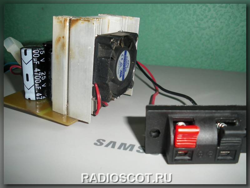
The subwoofer case is made of fiberboard of sufficient thickness so that there is no bounce and overtones. Outside, we glue it with a soft cloth for vibration absorption. We use standard tulips and spring-loaded pedals as connectors.


Two are used to indicate the modes of the subwoofer. Green indicates the supply of a 12V supply voltage to the circuit, and red indicates overloads and protection trips in the TDA1562


The 12V power supply must be screwed in to improve contact and reduce losses. Tests of the finished subwoofer have shown that the sound is no worse than branded mid-range subwoofers, and it is quite possible to assemble a good bass system in a car with your own hands in just 35 and two evenings. Material sent by - in_sane
Discuss the article DIY SUBWOOFER