Biostar has announced the release of two new Hi-Fi A88S2G and Hi-Fi B85S2G motherboards, which are equipped with 2 LAN ports. According to the manufacturer, these products are aimed at gamers who are fans of online battles.
The main advantage of the presence of two LAN ports in Biostar is the possibility of organizing full-duplex transmission. You can download and transmit information on two networks at the same time. It also speaks of zero packet latency thanks to the presence of two high-speed Gigabit ports. For load balancing, the user can connect network adapters to the same network. The new Biostar motherboards will support teaming functionality. Two ports allow organizing a multi-mode of such aggregation.

As a result of having two network interfaces, the manufacturer says that it is possible to turn a computer into a complex router. Of course, this will be a software router, but if it does not require an investment, then why not. This is even a plus, since such a router offers much more settings than a standard router.
Apart from that, you just get a spare network port. So, if one port suddenly fails, then you will have the other at your disposal. In terms of sound options, Biostar is talking about support for 3D Audio, 3D Smart Ear, True Blu-Ray Audio, 3D HiFi Amp. Audio processing is handled by the Realtek ALC892 audio codec. DirectX 11.1 support and AMD Eyefinity technology are also reported in the case of the A88X chipset.
Now more about the boards themselves. Hi-Fi B85S2G model based on Intel B85 chipset works with Haswell processors, where TDP is limited to 95W. The motherboard has 2 DIMM DDR3 slots in the arsenal. They can accommodate modules with a frequency of 1066/1333/1600 MHz. Maximum capacity up to 16 GB of RAM. There are PCI Express 3.0 x16, 2.0 x4, 2.0 x1 slots, as well as 3 PCI slots for installing expansion cards. For connecting drives there are 4 x SATA 6 Gb / s, 2 x SATA 3 Gb / s. The food is organized in a 4-phase scheme.
The Hi-Fi A88S2G model was designed by Biostar engineers based on the AMD A88X chipset and socket FM2 +. Work with such APU families as Richland, Kaveri, Trinity is supported. TDP of supported APUs up to 100W. Memory slots for DDR3 with frequencies from 800 to 2600 MHz, and the maximum memory capacity is 32 GB. There are 8 SATA 6 ports for drives. The board has 1 PCI-E 3.0 x16, 2x 2.0 x1, 3x PCI slots. The same Realtek ALC892 is responsible for the sound.
Similar materials.
There are network adapters on the market with one, two or more inclusion ports, which significantly expand the capabilities of conventional network adapters. To ensure constant access to the Internet at home and in small offices, a computer is used as a gateway.
The need for network interfaces
To do this, he needs to have two network interfaces. This can be achieved in two ways:
- using two regular network adapters;
- using one network adapter with two ports.
In the first case, the external interface is connected to one network adapter, the internal interface is connected to another. During network operation, there is a constant exchange of data between the two adapters through the motherboard.
The advantages of the second method are obvious: the throughput of such a gateway is increased by eliminating the loss of speed for data transmission between network cards.
In fact, at the software level, a network adapter with two ports is defined as two network interfaces with a very high data transfer rate between them, since the exchange occurs within one card, bypassing the system data bus, the speed of which is often limited and much lower than the speed of the adapter, this especially noticeable on gigabit cards due to the high network load.
Another interesting feature of such a solution is that the adapter can operate in the hub mode: without processing or broadcasting packets, providing maximum bandwidth at the expense of security. However, such solutions have not been used for a long time, since the computing power of modern computers allows them to easily operate in switch mode.
Operating modes

Two network interfaces allow for redundancy of an external Internet channel, which is especially important in gateways for corporate networks. Redundancy is achieved by connecting to two Internet providers and constant software monitoring of two connections. There are two modes of operation of such a scheme:
- main-backup (master-slave) - there is a permanent high-speed connection and a backup, which is used only in case of a break in the main;
- alternate switching (round-robin) - there are two peer-to-peer connections that are switched alternately (hourly, by time of day - at the discretion of the administrator). It is mainly used to save money in cases of different tariffication of providers.
What if you use two connections at the same time? Nothing prevents you from running a torrent client on such a gateway and downloading gigabytes of information in several hundred streams over two connections simultaneously, thus summing up the bandwidth of the channels.
However, in the case of using such a computer as a server providing access to data, the speed does not increase, because the client connects only through one of the external channels.
The most unpredictable application of such an adapter can be a network repeater, which allows you to increase the maximum effective network cable length without packet loss. Also, such an adapter can have different ports on the physical layer. For example, the first is Ethernet, the second is fiber optic or coaxial.
Due to this, it can be used as a media converter (physical layer converter). These network adapters are used primarily in advanced high-end enterprise-class equipment.
Thus, the choice of a network adapter with two ports is more logical, because it allows not only to save on connectors on the motherboard, but also to increase the data transfer rate on your network.
Almost any network adapter, be it a computer adapter or a network printer, is equipped with an indication system in the form of one or more LEDs. These LEDs indicate the current state of the connection to the central unit (switch). In today's article I will tell you how you can check the health of a network at the physical layer (signal layer).
Find the LED on the network card of a computer belonging to your network Link - it should burn green light... This LED indicates the presence of a physical connection. The switch should also be lit by the lights above the ports to which the cables from the computers are connected.
So if the LEDs on the network cards and the switch are green, then you have crimped and connected the cables correctly.
If a indicator is off, this may indicate the following:
1. Computer or switch not included.
Make sure the computer and the switch have stable power and are turned on. You can also reboot the switch.
2. Defective network card.
Make sure the network card is visible in the “Device Manager”. If this is not the case, then it may be disabled in BIOS or incorrectly installed in the connector on the motherboard. Try replacing it with a different network card.
3. Defective switch port.
It happens that some ports “burn out” in switches. Push the cable to a different port.
4. Possible poor contact in the connector, or the connector is not fully inserted into the socket.
In this case, remove and insert the connector back into the slot of the network card and switch.
5. Damaged cable.
Take another crimped cable and connect it to the problem computer and the switch. If the LED is on, then either the cable was really damaged or the following problem is occurring.
6. Wires are reversed when crimping connectors.
There is only one way - to cut the end of the cable with the connector and re-crimp the cable again.
After fixing the problem with the unlit Link indicator, take a look at the indicator Act ("activity"). He starts blinkwhen data is being exchanged over the network cable. In some models of network cards, there is only one indicator or a two-color LED: it signals the presence of a physical connection with a continuous light, and during data transfer it blinks or changes color.
By the way, to check the performance of the network cable, you can use a special device - LAN tester: allow testing cable wiring, breaks, distance to break, segment length, signal attenuation, etc. In general, the network tester is a very handy thing. But if there is no such tester, you will have to make do with the simple methods mentioned above: replace cables, switch to another port, etc.
In the past, people didn't really think about the speed of cable connections on their home network. They have always provided sufficient speed and reliability, which in any case has been proven by their use millions of times. However, these days the technology has reached its limit: an increasing number of computers are installing solid state drives, the speed of which is at least five times the speed of 1 Gb / s. And the new 802.11 "ac" and "ad" wireless networking standards significantly exceed gigabit Ethernet speeds.
Of course, there are cable technologies that can provide speeds up to 10 Gbps, but they are designed for professional data centers and are quite expensive. But there is another possibility of providing a higher speed. It consists in the interconnection of several gigabit networks. In a similar scheme, the so-called. "Link Aggregation", two common Gigabit LAN cables are connected to provide excellent integration into an existing network. However, there are some obstacles to implementing the simple 2 × 1 Gbps \u003d 2 Gbps principle in practice, which we found in our tests.
Link aggregation: network switches from 2500 rubles
The main element for link aggregation is the network switch, which must support this function. In most home networks, there is only a switch built into the router - these are its LAN ports. They often cannot connect with each other.
This opportunity is provided only by modern top-class routers, such as ASUS RT-AC5300 or Netgear Nighthawk X10 (each price starts from 20,000 rubles). However, for only RUB 2,500, LAN switches with 8 ports and link aggregation (such as TP-Link TL-SG108E or Netgear Gs108E) are available that can be switched between the router and networked devices (see diagram on the right).
Fundamental feature: the switch must be manageable (that is, a web interface is required to configure it, and the firmware installed in it must provide port connectivity). This is indicated by one of the terms "Link Aggregation", "Port Trunking", "LACP" or "802.3ad" in the datasheet.
 Computers or devices that need to connect at multiple Gbps must have an appropriate number of LAN ports and software configurability. We tested two scenarios using the Netgear GS110TP switch. In the first, the NAS is connected to the switch via two LAN ports, so each of the two PCs can download data from the NAS at full gigabit speed.
This option is a targeted use of link aggregation and works relatively seamlessly. In the second option, we configured the PC with two LAN ports so that data could be downloaded from the NAS at 2 Gbps. This rather complex method involves very specific types of data transfer and often (but not always) provides double the speed.
Switch structure and configuration
In any case, you first need to start the switch: it is connected to the electrical network through its own power supply; one of its ports connects to a router (we used the last port # 8). In about a minute, it will boot up, its LAN ports will work, and the web interface will become available to all computers connected to the switch (or router) via a wired or wireless network.
The IP address of the switch can be found in the settings of your router, the preset password is indicated in the user manual. First of all, you need to search for updates on the manufacturer's website; for our Netgear switch, we needed to download the new firmware in the Maintenance | Download | HTTP File Download ".
 In the web interface of the Netgear switch, you can configure the link aggregation groups and connected ports
 Link aggregation can be configured before connecting the corresponding devices. In the web interface of the Netgear switch, in the Switching | LAG "click on" LAG1 "(link aggregation group) and check the" PORT "box next to the port numbers you want to use. Each group serves to connect one device: in the diagram on the top right, LAG1 is a NAS storage connected to ports 1 and 2, LAG2 is a PC on ports 5 and 6. In the "LAG Configuration" section, we left the default settings, only changed parameter "LAG Type" to "LACP".
The speed of ports that do not belong to any group remains at the usual level of 1 Gbit (in the diagram, these are 3, 4 and 8). Connect devices according to LAG identification. At first, only the simple cable connection to the physical first interface of the end device is active; link aggregation must also be enabled on endpoints. How to do this, read on.
Configuring the NAS for Dual Link Mode
For our tests, we used the QNAP TS-231P, which is equipped with two LAN ports and provides high bandwidth. We measured FTP transfer rates with fast SATA SSDs installed in both the NAS and the target PC. The network settings in the QNAP web interface are located under Control Panel | System Settings | Net".
Here in the "Interfaces" section, both Ethernet ports are shown. Click the Port Trunking | Add ”and check the box for each interface. The only mode that worked reliably with the Netgear switch during testing and yielded the required results was “Balance-rr,” which uses both cables alternately for data transmission.
 After clicking the Apply button, the NAS briefly goes offline to apply the new settings. If a mode is set that is not supported, the NAS will be unavailable; in this case, press and hold the button on the back of the device for 3 seconds. This will reset the password and return the network settings to their default values.
In theory, the basic link aggregation mode using two computers connected to simple ports on a Netgear switch should allow two files to be simultaneously downloaded from the NAS disk at a speed of 1 Gb / s each. But loading and downloading from two PCs knocks the system out of rhythm a little: when loading to a network drive, the speed is about 25% lower than the theoretically possible maximum.
Since this configuration is relatively affordable and easy to implement, it is certainly suitable for home networks where multiple computers access the NAS. However, it is worth paying attention to the following: while parallel data transfer helps to exhaust the capabilities of both network lines, it also places increased demands on the drives installed in the NAS device. It is advisable to use SSD drives.
Double the data transfer rate from the NAS server to the PC is also possible, but in practice this option is quite complicated, as we found out later.
Configuring Link Aggregation on a PC
Anything done on a NAS with a couple of clicks should be just as easy to implement on a PC. In any case, they think so. In terms of hardware, there are numerous motherboards with two LAN ports, or boards with the ability to install a second 1Gbps NIC for little money. From a software point of view, this becomes more complicated: this feature was originally supported in Windows 10. But after the fall 2015 update, utilities for this, although they exist, no longer work. This also applies to Intel network drivers, which can be used to configure link aggregation in an alternative way.
Therefore, we installed Ubuntu on a gaming PC with a Skylake processor and two network connectors, in which aggregation can be configured, in the Linux world called "Port Trunking". To do this, we first deactivated the Ubuntu Network Manager and then configured port aggregation using the Linux configuration file (“/ etc / network / interfaces”). In truth, we tested different options from the Internet until the technology worked on our test PC, as the documentation on the topic is rather scarce and often contradictory.
 Our successful combination consists of four interface definitions, each of which begins with "auto ...": first, we specify a system-critical loopback device that cannot be changed. In this case, both physical LAN ports are detected, but not activated. This only happens in the definition of "bond0" for the specified link aggregation interface. Most of the entries are for manual configuration of IP settings, the connection mode is indicated using the "bond-mode" string. Mode 4 is for 802.3ad connections and provides a maximum speed of up to 1628 Mbps.
Alternatively, mode 0 ("Balance-rr", that is, the same mode as in the NAS) works, but only at a speed of 1202 Mbps. For comparison: the data transfer rate on a single gigabit line is 912 Mbps. Fault tolerance is a positive concomitant effect: during data transfer, you can disconnect one of the two connectors - the connection does not break, only the speed drops by half.
However, there is at least one catch: both lines are only used if two files are simultaneously transferred via FTP (in Filezilla's settings menu: "Transfers | Maximum simultaneous transfers: 2"). When this value is increased, the speed decreases very quickly. In addition, you must pay attention to the fact that there is no other connection between the PC and the NAS server (for example, the open web interface of the NAS, SSH connection), since even the minimal line load leads to the fact that both data transfers are carried out only one line instead of two.
An additional disappointment: the speed while experimenting with the SMB protocol that Windows uses to access files remotely was significantly slower than over a single gigabit line. All of this demonstrates the low likelihood that Windows link aggregation mode could function quickly and without problems, since the Microsoft system retains control and other connections.
Our takeaway for link aggregation is that the process is well suited to efficiently connecting a NAS server to multiple gigabit clients. As a quick NAS to client connection, it is time consuming and has many pitfalls. This would require a fundamentally faster network technology.
 SFP + as the New 10 Gigabit Standard
The Netgear Nighthawk X10 router is equipped with an SFP + interface, so you can connect a device with a data transfer rate of 10 Gbps to it. Its two gigabit LAN ports are linked together through link aggregation.
10 Gb Ethernet and SFP +
In the professional field, the 10 Gigabit standard has formed the backbone of the infrastructure in data centers for over a decade. The copper variant called "10GBase-T" relies on the same RJ-45 connectors as the Gigabit LAN, but requires shielded (at least Cat. 6) cables and expensive hardware such as a network card such as , Intel X540-T1 costs about 22,000 rubles, the cheapest switch with two 10GBase-T ports (ASUS XG-U2008) is about the same. NAS-drives supporting this standard cost from 50,000 rubles.
 Professional card
HP NC523SFP NIC adds two SFP + interfaces
The "SFP +" standard is more accessible. It describes a compact, modular transceiver used in cabling and is designed for both copper and the much more expensive fiber optic cables. Both options provide data transmission at a speed of 10 Gbps: copper cables for a distance of 50-100 meters, fiber optic - up to several kilometers. The Netgear Nighthawk X10 router is equipped with one SFP + port. Using the SFP + Direct Attach Copper Cable module (about 2500 rubles), you can connect a NAS drive to it.
The cheapest SFP + model is QNAP TS-531X-2G (from RUB 48,000). PCIe network cards that support SFP + are available starting at RUB 15,000. (Warning! Most of them work only with the drivers of the server version of Windows!) However, as the Netgear router shows, the situation is that SFP + can penetrate the mass market and "blow up" the gigabit border.
PHOTO: Manufacturing companies; CHIP Studios
Greetings to all, dear readers of the blog site! In my previous articles, specifically -, I mentioned some ports or connectors, which are literally "stuffed" with any modern motherboard. So, in this article we will try with you to figure out the purpose of these connectors.
Connectors on motherboards can be located both inside the computer case (we do not see them), and outside - on the back and front of the system unit. The latter often duplicate each other for the convenience of connecting various devices. All the information that will go below is also relevant if you have a laptop, because its ports are no different from those on a regular PC.
And this is the first category of connectors, perhaps the most extensive of all. It includes a large number of connectors on the computer's motherboard. If you are already familiar with the computer device, then you should know that the motherboard is the most important “board” in the computer, because all other components are connected to it, such as: processor, video card, RAM and others. Therefore, all these devices have their own connectors.
CPU
A processor socket on a computer motherboard is also often called a "socket" (from English - "socket"). Let's imagine that the socket is a lock, and the processor is the key to it. It turns out that only your own key is suitable for a single lock. Only in our case, several “keys” (processors) can come to the conditional “lock” at the same time. Do you understand what I mean? Each socket limits the number of processors that can be installed in it. I already had a separate one, I recommend reading it.

Determining the location of the socket is easy, it looks like a large square with many "holes", or "pins", and is located almost in the very center of the board - closer to its top. Different processor firms use their own sockets, for example, the following socket types are suitable for Intel:
- Socket 1150
- Socket 1155
- Socket 1356
- Socket 1366
- Socket 2011
But AMD processors use these sockets:
- Socket AM3
- Socket AM3 +
- Socket FM1
- Socket FM2
RAM
For RAM, the motherboard also has its own connector, or rather several. They have an oblong shape and are located slightly to the right of the processor, and their number, as a rule, does not exceed 4 pieces. At the time of this writing, DDR3 memory is already widely used in the world, although DDR2 is also found in some places. You can read about all their differences.

Now, we are only interested in the fact that DDR2 and DDR3 have their own ports. And you can't just take and install DDR2 memory into the DDR3 port, it just won't fit there. By the way, these differences in ports are noticeable even visually. And also, when looking from above, you can notice a different color of these connectors, for example, from 4 ports for RAM - two of them are painted in one color, and the other two - in a different color. This is the so-called "two-channel" mode.
Video card
There is also a video card connector on the motherboard. Once upon a time, to connect a video card, the AGP interface was actively used, which was then successfully replaced by PCI e x16 or PCI express x16. In this case, the number 16 is the number of lines. There are also x4 and x1, but you can't install a video card in them.

The video card connectors are located at the bottom of the motherboard, and there can be several of them, I mean PCI express x16. True, this is not often found, only on "gaming" motherboards, and all this is needed to create an SLI or Cross Fire. This is when several video cards, often no more than two, are connected to the motherboard and work in parallel, that is, their power is combined, roughly speaking.
HDD
As an interface for connecting a hard drive to a motherboard, a SATA cable is often used, which is connected to the corresponding connector. There are other connection options, such as IDE and FDD, for example. FDD is no longer used, it used to be used to connect a floppy drive, where floppy disks were inserted. In the past, IDE was the main option for connecting hard drives, until it was replaced by the Sata connector.

Now even optical disk drives (CDs) are connected to the motherboard using a SATA connector. There are various generations of Sata that look the same but differ in data transfer rates. Also, there are varieties of the Sata connector - "eSata", "mSata", which are already structurally different. In addition, some HDDs can be connected via a USB port, not to mention "SCSI", or no less exotic "Thunderbolt".
Nutrition
On the motherboard, the power connectors are located in two places: next to the RAM (24-pin connector) and just above the processor socket (the processor power can be seen in the diagram at the very beginning of the article). If at least one of these connectors is not connected, the computer will not work. On older motherboards (before 2001-2002) this connector had only 20 pins, but now their number can be in the range of 24-28. This is the main power connector for motherboards.

Cooling
Without cooling, no computer can work for a long time, therefore, for effective cooling, the computer has coolers (fans), the most important of which is designed to cool the processor and is installed right on it. To power these fans, the motherboard has special connectors with two, three or four pins:
- 2 pins - this is a normal cooler;
- 3 contacts - fan with tachometer;
- 4 pins - the cooler uses a pulse-width converter, which allows you to change the speed of its rotation. The processor cooler is connected to this connector.
If desired, ordinary fans (without the possibility of speed control) can be powered from the Molex connector of the power supply. This may be necessary if the motherboard has no free connectors for coolers.
Additional devices
This number includes a variety of additional expansion cards: audio cards, network cards, RAID controllers, TV tuners, and so on. All of them can be connected to the motherboard through the PCI connector, but not which is "express", but the usual one. This also includes the round-shaped connector for the "CMOS" battery, because of which the time on the computer does not get lost every time you turn it off, just as the BIOS settings do not get confused.

Pay attention to the CD IN connector on the motherboard, it is necessary to connect CD drives with the ability to listen to CDs and control - switching tracks forward / backward. Pins labeled as "SPDIF" stick out somewhere nearby - this connector can be used to connect a home theater, for example. To do this, a special bracket is ordered with this port, which is attached to the rear wall of the system unit, the bracket is connected to the motherboard via a cable.
The SPDIF port is usually found on expensive motherboards. It is not installed on budget models, but on the board itself you can find pins for connecting this port.
On the front panel of the system unit
For convenience, on the front panel of any modern (and not so) computer, there are several USB connectors, as well as an input for connecting headphones and a microphone - the latter is usually painted pink. But, as you can imagine, these connectors will not work by themselves, they must be connected with wires to the motherboard. For this, it does not provide contacts that are signed accordingly.
The same manipulations must be done with the audio outputs (group of contacts "FP Audio" or "Front Panel Audio"), as well as with the card reader - if it is installed on the front panel. The card reader is an extremely convenient device for reading memory cards and must be connected with wires to the pins for connecting the USB ports.

And on the front panel you can often find an IEEE 1394 (FireWire) port, used to connect digital devices such as a photo or video camera. And for him on the motherboard, contacts are also provided, which are signed. In general, they always write about where what and how to connect in the instructions for the motherboard, but, as you can see, it is quite possible to figure it out yourself.
Well, everything seems to be (just kidding), there are also on / off buttons for the computer and LED indicators for its operation. To connect them, a special area with contacts is allocated on the motherboard, located closer to its bottom (next to the battery). I must say right away that there is no single standard, so the type and location of these contacts on each motherboard may be different.

So, the computer power button and the Reset button are connected to the motherboard using the Power switch and Reset switch connectors, respectively. With the help of similar connectors, the computer operation indicator (Power Led) and the hard disk loading indicator (HDD Led) are connected. These connectors look like small plastic "pads" with two wires (2 "pins"), one of them is a plus, the other is a minus.
 Wide
Wide  Small
Small
There are two types of connection (2 types) of contact pads on the motherboard, reserved for buttons and indicators of the front panel:
- wide connection is the most convenient option;
- small connection;
- no inscriptions at all. For example, many MSI boards do not indicate designations at all, and you can figure out the connection there only with the help of the instructions.
On the back of the system unit
There are many connectors on the back of the system unit, some of which completely duplicate those on the front. Their number can be completely different, again, it all depends on the motherboard model.
PS / 2
Today this connector is considered obsolete, but on many motherboards it is still present and feels good, so to speak. Used to connect a mouse or keyboard. It is noteworthy that there are USB to PS / 2 adapters.

COM port
It is almost impossible to find a COM connector on modern motherboards. Previously, it was used to connect all kinds of printers and other peripheral devices that are now connected via USB. The COM port has an analogue - LPT, which is even less widespread, it has an oblong shape and is colored pink.

USB ports
As a rule, if there are 4 of these connectors in front, then at the back there are at least no less of them. Again, everything is done so that you can connect as many devices as possible to your computer at the same time. And if the front ports are usually occupied by all kinds of flash drives, then "long-playing" devices are often connected to the rear ones, that is, which you will not constantly connect / disconnect. Well, for example, it can be a keyboard with a mouse, as well as printers, scanners.

There are two main flavors of these ports:
- USB 2.0
- USB 3.0
Of course, the third version is preferable due to the higher bandwidth, such a port is even marked with a different color - blue.
USB 2.0 and 3.0 are compatible with each other.
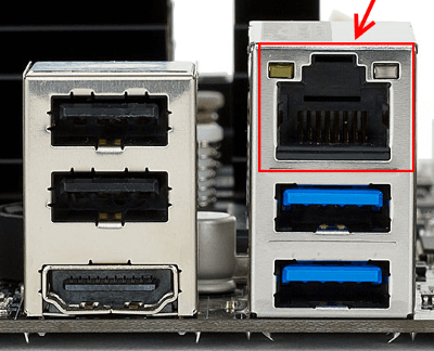
Network and Internet
One single connector is responsible for the network and the Internet - "Ethernet", which is sometimes called "RJ 45". If you look closely, you will notice that there are small "windows" on this connector - these are indicators of the network operation, when data is being transmitted, they signal this. If the indicators are off, most likely the connector has stopped working and needs to be re-crimped (using a special crimp).
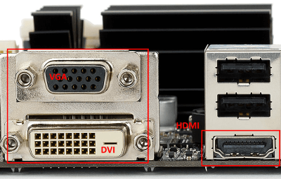
Video
Any monitor is connected to a computer (motherboard) using video connectors, which are located on the back. There are quite a few varieties of them, it will not be entirely appropriate to talk about each here, especially since the site already has a separate article about. In my opinion, only three of them are the most popular video ports:
- analog VGA port
- digital DVI
- digital HDMI
The rest are not so popular and are rare.
Audio
Usually - three or six inputs for connecting multiple speakers and a microphone. On boards of the budget segment, the number of audio connectors usually does not exceed three, but at the same time, all the necessary functionality is present, and this is:
- Red - for a microphone;
- Green - for speakers;
- Blue - for connecting external sources, such as a TV, player or radio.
If your motherboard has six audio outputs, then know that the other three are used to connect additional speakers and a subwoofer.

Laptop-specific
It is worth saying a few words about rare, I would even say "exotic" connectors that are found in laptops or some other devices, but which cannot be found on a regular PC. These are two connectors: PCMCIA (ExpressCard) and Kensington Lock. The latter is used to protect the device from theft. A special cord with a lock is inserted into the "Kensington Lock" slot and tied to any object, be it a table or a battery, for example. Naturally, only you have the keys to the lock.
 ExpressCard
 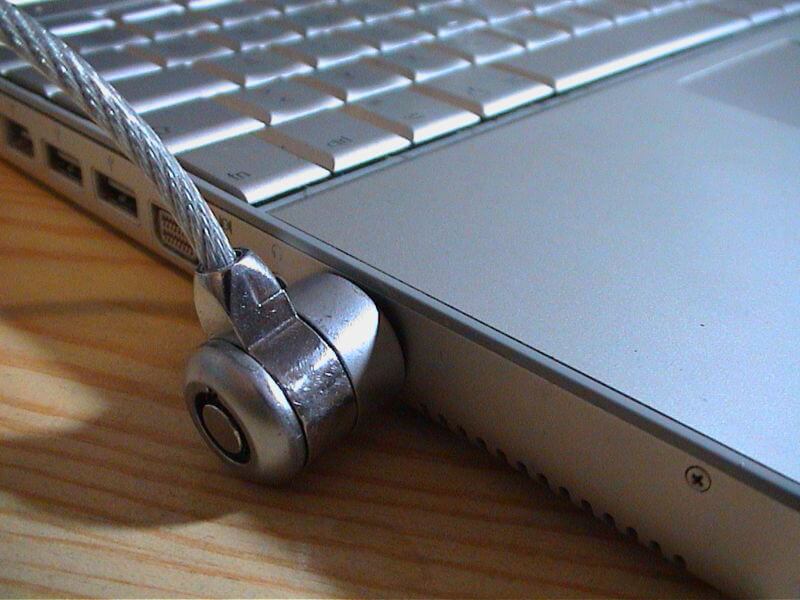 Kensington lock
But the "ExpressCard" is a narrow slot, covered with a flap, into which a kind of expansion card is inserted, on which ports for connecting other devices can be placed. With the help of such a card, you can easily add yourself a few USB 3.0 ports to your laptop, if only because there is a shortage of them on any laptop.
Well, that's all, we have sorted out all types of connectors that can only be found in a computer, if I suddenly missed something (the article is long, you understand) - write about it in the comments.!


