I have been interested in the issue of camera stabilization for photo and video shooting for quite some time. There were experiments with various vibration isolations, as well as with the use of servos, but later it turned out experimentally that all this was not the same. With the advent of systems on brushless motors on sale, I took a closer look at them and decided to buy a two-axis gimbal to stabilize the camera.
I ordered it as a set - a gimbal with a controller. The choice was quite simple; the main requirement for the gimbal was the ability to install a 200-300 gram camera. There are not many offers for these purposes, especially at reasonable prices. The choice fell on a gimbal from ASP and a BGC controller like this one 
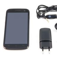
There were two colors to choose from: black or blue. To be honest, blue on an aircraft would look “sloppy”, so I definitely chose the one painted black.

The contents of the box are divided into bags. The large bag contains all the metal structural elements. Separate package with dampers. The package with fasteners contains several bags of screws of different sizes. The motors were wrapped in packaging material, the wires were located separately, you need to solder them yourself. Two plates of textolite, covered with carbon fiber, were laid on the bottom of the box. And best of all, the BGC Brushless Gimbal Controller comes in a sealed bag. That's all the contents of the box. The total weight of the parts in the package was 661 grams.
The photo shows all the design elements.

The engines are impressive. This gimbal is equipped with GBM 5010 14N12 motors.

The motor is wound with 0.21mm wire, 150 turns, resistance 14.65 Ohm.

Let's start assembling. Due to the fact that the suspension is made of metal, we must use a thread locker. The elements slide into one another and are secured with screws.
There were no assembly instructions in the package with the parts, and I couldn’t find them on the Internet either, so I assembled them using photographs from the Internet.
I assembled three brackets.
I installed the engines in series.
An adapter was previously installed on the engine responsible for Pitch.

We solder the wires. I soldered (if you look at the motor as in the photo) - brown, red, yellow from left to right.

The vibration decoupler consists of two plates connected to each other by twelve dampers.

The dampers are made of thin silicone, elastic, fit securely in the mounting holes and do not dangle.
The dampers work in compression, so the mounting posts pass through the technological holes in the plates, and the suspension and the platform itself are mounted to the aircraft onto the posts.

The mechanics combined with the camera look quite nice.

The next stage of assembly is to install the electronics.
The controller, as I already said, took 2-Axis Brushless Gimbal Controller & IMU v1.0.

The connectors are already soldered to it. The wire to the gyroscope is quite thin and soft. The only thing that confuses me is the connectors, which do not fit tightly enough into the sockets and pop out if you accidentally pull the wires.

On the bracket behind the motor along the Roll axis there is a platform for mounting the controller. I had to put insulating washers under the screws, since there is a printed circuit on one side of the PCB close to the mounting hole.

The sensor is located on the base of the platform under the camera. There are holes for its fastening. Screws included.

The power connector is in the form of two protruding contacts. There is no locking latch provided. On the board near the connector there are large + and - marks. There are many messages on the forums related to incorrect connections, due to which the controllers fail; there is no electronic protection.
The board's power supply is stated to range from 2s to 6s. I decided to power it from a 3s battery.
I connected the receiver to the contacts signed on the controller A1 and A2. I adjusted the tilt angles using knobs.
I downloaded a new version of the program from the official page http://code.google.com/p/brushless-gimbal/downloads/list
I connected the controller to the computer via a USB cable, the drivers were installed automatically, and the com port appeared in the device manager. But when I launched the program, I saw that the result was zero.
A search for information on the Internet showed that there are similar problems that boil down to reinstalling the drivers http://www.ftdichip.com/Drivers/VCP.htm. But this measure did not bring me positive results. I tried different versions of drivers, but the program did not see the controller.
It was also not possible to reflash it according to this instruction - http://www.rctimer.com/download/BGC-Manual.pdf.
Arduino IDE gives errors and does not flash. As it became clear later, you need to add a special one - bootloader.
Having lost hope, I decided to try an earlier version and downloaded BETA Version 048 incl GUI. By the way, on the page with a list of firmware versions, there are only beta versions, as if there was never a stable working version all the time. After clicking the connect button, the status field finally turned green.

The GUI showed that version 48 of the software was loaded into the board's memory. All default controller settings are in the screenshot.
After clicking the Start button in the Chart graphics window, you can see that data is being received from the sensors along the Pitch and Roll axes. Two curves appeared on the screen.

Now you can try the gimbal in action. Having connected the power, the controller is initialized, rotating alternately along each axis, after which it is leveled to the horizon. To try it out, I placed the pendant on the table upside down. I installed the camera and balanced it taking into account the already installed camera. Adjustment is carried out by changing the length of the arm of the brackets.
As it turned out later, I soldered the wires and connected them correctly the first time, I didn’t have to change anything.
This is what I got with the factory settings.
As a result, I want to draw the following conclusions:
Overall, this kit made a positive impression.
The suspension is made with high quality, the parts are precisely machined and easy to assemble. The painting of the parts leaves a pleasant impression. The fasteners are arranged in bags according to size, with a large supply of screws.
I had to tinker with the software a little. I'm currently using version 48. To change the firmware, apparently, you need a programmer, which I don’t have yet.
The controller is currently working with default settings. Along the Pitch axis, the gimbal does not work as expected, this is clearly visible in my test video; additional adjustment of the PID parameters in the GUI is required.
The system operates very smoothly; when recording video, there are no jerks or lags inherent in servos.
The weight of the structure including the camera, but without the battery, was about 750 grams. If you add a 12 volt 3s battery, then the weight will already approach a kilogram.
Among the disadvantages of this suspension, I note that the gyroscope is placed on the base and is not covered by anything, I suggest moving it to another place or making protection. And the controller could use a housing or, for example, try installing it on the base of a vibration decoupler.
Any person more or less associated with aerial photography knows what the role is camera gimbal for quadcopter. Namely, everyone will answer that without a good gimbal there will be no high-quality picture even with a professional camera of the latest model. Undoubtedly, the quality of the image primarily depends on the characteristics of the camera, but the gimbal also plays an important role here.
So what is the role of a camera gimbal? The most important thing a gimbal gives a camera is stabilization. It is due to the stabilization work that the pictures will be clear and not blurry. Of course, all gimbals existing on the market are aimed at maximizing stabilization performance, but each model has a certain number of errors. These errors are caused by completely different reasons, ranging from the weight of the camera to the physical forces that influence it. Another important criterion is the viewing angle. The likelihood of a good shot is proportional to how wide the viewing angle is open to the camera. And this, in fact, is not surprising and, I think, is understandable to everyone. The more you can see, the more good shots you can take. Secondary features are the presence of control modes that minimize the operator's work, allowing him to focus on piloting in the meantime. This is a useful and desirable factor, but not categorical.
At the moment, the leading position in the aerial photography equipment market is occupied by the manufacturer DJI. Quadcopters from this manufacturer are professional and high-quality, thanks to which they have won the recognition of many fans of aerial photography. And, as it is not difficult to guess, Dji camera gimbal It is also professional and popular among experienced pilots. And no wonder. For example, suspension Dji Zenmuse Z15-5D, designed for the Canon 5D Mark II\III DSLR camera, allows the camera to rotate around its axis, up\down and sideways at different angles, while providing maximum stabilization. Thanks to this, all pictures with such a gimbal are of high quality and good clarity. In addition, the gimbal has three control modes that allow you to fix it in the position most necessary for shooting, thereby minimizing the operator’s work and allowing the pilot to focus on controlling the quadcopter. Of course, the price of such a suspension is appropriate, but by purchasing it, everyone can make sure that it is absolutely justified. And do not forget that only high-quality equipment can give high-quality results.
Aluminum two-axis gimbal for quadcopter to stabilize the camera on brushless motors. The BGC controller allows you to fine-tune the operation of the gimbal by connecting it to a computer via USB.
Characteristics
Calibration
- press the button 1 time to calibrate the accelerometer
- press the button 2 times to calibrate the gyroscope
- press the button 3 times and the current position will become the default position
- long press causes reboot
Note
- Turn on the gimbal when the camera is in a horizontal position. When connected without a camera, the gimbal will jerk erratically.
- Don't try to reflash
- Maintain information about initial values when changing settings
Connection to V303
We did not change the settings in SimpleBGC:


Gimbal settings from another batch that we liked better: 


When you press the gimbal control buttons, the RC_PITCH or RC_ROLL values change: 
The power was taken from the balancing connector of the battery, but you can also take it from the connector near the USB on the bottom of the quadcopter: 
To control camera tilt up and down, connect to the left group of contacts. The purpose of each of the three pins is labeled on the board. Suspensions may be of different revisions and the group may be different. Find the one you need by changing groups (left or right) with the gimbal turned off. If the pins are not labeled, then see the instructions included with the pendant. Usually the pin closest to the edge of the board is the “ground”, and the farthest pin is the “signal”. 
They wrote on the Internet that it is enough to connect S to the white wire, but this option did not work for us. We connected S(signal) to the white and GND(-) to the black wire. 
Never connect power from the battery directly or through the connector near the USB to the + and - pitch / roll channels.
I think many people are familiar with this situation: you are filming something exciting, dynamic, amazing, and you think: now I’ll come home and edit an action video! However, when viewing the footage, you begin to spit because half of it can be safely thrown away due to terrible shaking, which in 30-50% of cases cannot be stabilized by software. What to do in such cases? If you want to shoot dynamics, high-speed camera flights, and not stand with a tripod and a sad face, then this thing is for you!
The main thing this gimbal does is stabilize the picture along 3 axes. Simply put, it is an electronic steadicam. However, compared to a regular “mechanical” steadicam with weights, this thing performs its functions much better. At the moment, the choice of such suspensions is huge and their price range is quite diverse. But if you have never dealt with such things, then this article will be useful for you. Based on my experience, I will tell you which parameters are most important and what to pay attention to.
So, first of all, I’ll tell you about the suspension that I ordered from China.
Having never held such things in my hands, the question of choosing a suspension was difficult for me. Why do some suspensions cost 20 thousand rubles, others 50 thousand rubles, and others generally about 100 thousand rubles? Of course, not understanding the difference, I did what any Russian would do - I took the one that was cheaper. :)

A year ago I bought this suspension for 21 thousand rubles. I managed to order just before the dollar took off. I don’t know why I took him. Apparently I liked it. In addition, I begged the Chinese for a discount in the form of a couple of tens of dollars and free EMS delivery.
So, the long-awaited day came and I picked up a huge box from the post office.


It was packaged perfectly. The pendant arrived almost assembled (90%)
In his complete set included:
- Carbon frame;
- 3 Ipower 5208 200T engines;
- 3-axis alexmos controller;
- Joystick;
- Paralon handles;
- And other wires.
All wires, if possible, are hidden in pipes and routed inside the engines - this is very convenient because nothing sticks out.
Having assembled and tested my purchase, I can say the following:
- Works well with canonmark II;
- Convenient adjustable camera mounting platform;
- The design of the frame assumes the installation of both small “pancakes” and long-focus lenses (tested with 24–70 mm, 50 mm, 70–200 mm);
- I don’t see the point of setting it more than 50 mm. Then you definitely can’t do without software stabilization. I’ll try to adjust it in the future, but at the moment it’s shaking with the long-focus lens;
- Sufficiently large tilt angles;
- Enclosed engines. As I noted earlier (for mounting on a hexacopter), closed motors are a very useful thing, because... prevents the entry of dust and dirt;
- The gimbal is controlled and modes are switched using the included joystick.
These tubes were inserted into the arms of the suspension (20 mm tubes) and it seemed to stand securely “on its feet” and looked like a robot).

However, it was difficult to call such legs “quickly retractable”... and they did not fold. So that filming did not turn into just setting up and removing legs, it was necessary to come up with something else. As a result, after much thought, the following folding legs were made:

The principle of their operation can be seen in more detail in the video, which I will attach at the end. The main idea is that there are oval “holes” made in the tubes through which the shaft passes (by design it also connects two plates that “hold” the engine). And when the tubes are extended “away from the frame,” they move freely and rotate 180 degrees, and when they are moved “closer to the frame,” the tubes are fixed with their near end against this frame. Please don't make fun of the parts used to assemble the legs; I used what was at hand. :) P.S. rubberized “wheels” prevent the tubes from dangling. They kind of squeeze them.
As a result, I can fold and unfold these legs within 5-7 seconds, they weigh almost nothing, create no resistance to the operation of the gimbal, and do not need to be carried separately as a stand.
But my modifications did not end there.
Over a short shooting period, it became clear that shooting with a large depth of field is inconvenient because there is no way to change the focal length. In other words, it was possible to “twist” the focusing ring only directly with your hand on the camera itself. As a result of such manipulations, the engines were often disrupted and the picture, naturally, deteriorated. After some searching on Google, the principle of remote focusing was found. But the cost of such equipment, even in China, was actually more than the suspension itself.
I decided to do what we all love - “create a follow trick myself.” Dada, homemade again. But the invented way out of the situation justified this decision.
So, what does my follow focus consist of:
1) Servo machine. Based on the diameters of the focusing ring and the drive gear (which will control the focus), I realized that it was better to take the servo 360 degrees. Well, really from min. Up to max. The focus values could be increased. (because the standard 90 degree servo was not enough)
2) Drive gear*. This gear was supposed to be attached to the servo shaft and rotate the focusing ring.
3) Flexible focusing ring*. This ring fits over the main ring of the camera, which controls focus. The result is a “normal” focusing ring with large teeth for good grip.
4) Servo tester. With it, I could control the rotation of the servo.
In short, on paper it should all work. However, thanks to the mail, the drive gear never arrived from China. A workaround was needed. Having gone to a radio parts store, I found a very interesting and stylish “changer”. It was a cylindrical handle, with an internal fastening that matched the diameter of the servo shaft. All that remains is to somehow make the outer part of this cylinder look like a gear. Ultimately, I just took a similar flexible focusing ring, cut off the excess, and glued it into a small ring, the diameter of this cylindrical handle. I installed the same handle of a smaller diameter on the servo tester for smoother rotation.

Voila! Everything worked. When you turned the knob on the servo tester, the servo rotated the focusing ring. However, there was a problem. When the tester knob was turned to a certain angle, the servo simply began to rotate (slowly or quickly, but still rotating). That is, there was no fixed position. In other words, I could not turn the tester's handle to an angle X and at the same time know that the servo would turn to an angle Y. So I had to guess when to stop the tester.
After that, I decided to replace the 360-degree servo with a similar one, but 330 degrees. This is exactly what I need to fully turn the focus from the mines. up to max. meanings. After installing this servo, everything began to work as it should! The specific tester knob position was equal to the specific focus position.

This focus can also be controlled remotely by a second operator. The only difference is that the wire from the servo does not go to the servo tester, but to any RC receiver (I connected it to Frsky*), and the video from the camera went not only to the monitor, but also to the video transmitter. Then the second operator, guided by the second monitor, could take full control of the camera's focus. However, such work requires skill and teamwork. Therefore, after trying both methods, I settled on the option with a servo tester. I made the attachment of the follow focus without any problems - fixed. Because I use only 2 lenses, I chose the average follow focus position that satisfies both lenses.
As a result, the cost of such a follow focus at that time was no more than 4 thousand rubles. Perhaps it can be done cheaper if you replace the servo. But I decided not to save money and chose a servo with iron gears and high speed.
As a monitor, I use the simplest 7-inch monitor bought in a store, but the low resolution and detail make focusing difficult. It is often difficult to tell whether an object is in focus or not. Therefore, if you take a monitor for such a thing, then only an HD monitor, because these are not FPV flights, accuracy and picture quality are needed here.
At the moment, there are several more improvements planned, but I can tell you about this later, when they are all working. :)

Conclusion:
1) For $400 you can really buy a good working gimbal for a DSLR.
2) Of course, there are more sophisticated gimbals. They will work better (perhaps). For example, the same DJI ronin. I can’t say anything about it myself, but they say that there are no better pendants than it. All this is good, but its price tag in relation to my gimbal is the same as that of the inspire and phantom in relation to our homemade quads. But I can’t say that they work 5 times better. Therefore, in terms of price/quality, this suspension is optimal.
3) All attachments such as follow focus, etc. You can do it yourself, spending a little time and much less money than if you buy ready-made ones.
4) What cameras can the gimbal support? By chance I decided to put Black Magic on it. Not the Poket one, but the big heavy Black Magic. He got into this suspension very tightly, but he got up. And imagine my surprise when I turned on the gimbal and it worked! Those. there were no disruptions and the camera stabilized really well. Of course, you won’t be able to run and jump with such a setup, as it will most likely get torn off, but I walked around with it for quite a long time, and the camera never got torn off. Therefore, you can safely bet on anything lighter than Black Magic.
That's all. Wait for new articles. Thank you for your attention. :)
Final equipment:
- Suspension