It was a breakthrough in “handicrafts”. An article published in Russian that described in detail the process of building a projector at home based on an overhead unit. Although I had previously come across the French site AllInBox.com, I completely underestimated the information I found.
After reading the article in Russian and “entering” the essence of the process, several more resources on the topic were found.
The iXBT.com conference “Do it yourself home theater projector”, at that time one of the most theoretically savvy forums on the topic. The theory was discussed there, there were only a few practitioners, but theorists zealously built their virtual projectors. This is a good school for beginners. True, today there are already more than 130 pages and it is very difficult to re-read them in one gulp. I advise you to take a notebook and pen to take notes, because... there is a lot of material, the ideas are very interesting.
The already mentioned French site AllInBox. An excellent site completely dedicated to design engineering. A huge gallery of finished projects, theory, links, daily updates, in general, class.
One of the Russian-language resources dedicated to projector construction is the site “Homemade LCD projector for home cinema.” An excellent Russian-language resource, the theory is well described, a gallery of finished projects, a forum, everything on the topic. Respect and respect to the authors of the resource.
The theory was studied thoroughly, as it seemed then, but the manufacturing process itself was constantly postponed, then the topic was abandoned, first due to lack of funds, then time, then because of other projects.
At the beginning of the winter of 2006, after another fall of the Axis and a global reinstallation and cleaning of the machine, I came across the “Cinema” folder in my bookmarks, and again I became interested in the topic. The theory was repeated in just a few days, and the harsh practice of project construction began.
First a little theory
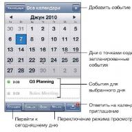
Our projector is no different from the usual “projection apparatus” that we all studied at school in physics lessons. A projection device is an optical device that forms optical images of objects on a scattering surface that serves as a screen. Based on the method of illuminating an object, diascopic, episcopic and epidiascopic projection devices are distinguished. In our case (in a diascopic) projection device (overhead projector), the image on the screen is created by light rays passing through a transparent object (in our case, through an LCD matrix).
Diascopic projection apparatus: 1 - light source, 2 - condenser, 3 - object (LCD panel), 4 - lens, 5 - screen.
In our case, the “light source” is a lighting system consisting of a metal halide lamp, a spherical reflector and a capacitor. A metal halide lamp, with its low power, produces a very powerful luminous flux, plus it provides a color temperature that halogen lamps cannot provide. Plus, the operating time is about 10,000 hours, and it does not burn out like a halogen, but simply loses its brightness. A spherical reflector that stands behind the lamp and reflects light coming in the opposite direction from the LCD matrix.
Today, some enthusiasts use LEDs as a light source, and get good results. http://www.allinbox.com/DARTG_BOX/DARTG_BOX.htm very worthy LED project.
The “condenser” in our case is two Fresnel lenses. It’s like a regular lens, only flat, due to the fact that its spherical surface is in the same plane in the form of grooves.
The “object” in our case is a matrix from a regular LCD monitor or TV. She works for the light.
“Lens” is a triplet. A lens consisting of two convex and one concave lenses to correct aberrations (such distortions).
“Screen” is a homemade screen made of banner fabric.
In general, the light from a metal halide lamp through a condenser lens, passes through the first Fresnel, passes through the matrix, thereby receiving information about the color of each pixel. Then it passes through the second Fresnel, collecting into the lens. It passes through the lens and forms an image on the screen. In my case, there is a mirror between the second Fresnel and the lens to rotate the light 90 degrees.
There are also such issues as the body, cooling, focusing mechanism, cooling shutdown delay timer, we will consider these and other issues as we work on the project.
In general, there is a huge amount of room for fantasy, and the most important thing is to understand the principle of its operation, and the rest is a matter of technology. In the above sources you can find a lot of information on the theory of design engineering, as well as many practical implementations of the project, you can see how certain components of the system are made (installed, which ones are used).
A huge gallery of finished projects on the AllInBox website http://www.allinbox.com/allinbox2007.htm - and this is just for this year.
Decision-making
First you need to decide on the choice of components, that is, matrix diagonal, lamp power, lens type, etc. After weighing all the pros and cons, the decision was made: Matrix - 15”, Lamp 250W, Lens from Lumienlab for a 15” matrix, everything else along the way.
To make a positive decision on the construction of the projector, an estimate was drawn up, which was adjusted during implementation. Before construction began, it was just under $400. Really decreased due to the purchase of a used monitor. So we’ll say that the projector cost $350.
Construction costs:
|
TOTAL: |
1665,525 |
||
|
the name of detail |
Price, UAH. |
Comment |
|
|
Reflector |
polished stainless steel bowl |
||
|
Lamp holder (socket) |
Cartridge E40 |
||
|
Capacitor |
28 µF 250 V |
||
|
Power cable |
From monitor 15 XEROX |
||
|
Capacitor (optical) |
Conder Ф120mm+70mm |
||
|
1 grill for 80 mm valve |
|||
|
Light block housing |
Aluminum |
||
|
UV-IR filter |
|||
|
S15 kit + delivery |
|||
|
Matrix LCD |
|||
|
Controller+Inverter+PSU |
|||
|
Keystone mechanism |
2 studs + 48 nuts |
||
|
Lens |
S15 kit + delivery |
||
|
focusing mechanism |
Furniture slide + PVC pipe + motor |
||
|
PVC 4 mm 1000x3000 |
|||
|
Fans |
4 valves D 80 mm |
||
|
PSU for fans |
BP12V + parts for timer |
||
|
Frames for fastening fresnels and matrix |
Aluminum |
||
|
regular from glass cutter + wash |
|||
|
Mirror frame |
Aluminum |
||
|
Banner fabric EcoBaner |
|||
|
Screen folding mechanism |
Printer motor and gearbox D219 |
||
|
Electrical accessories |
Buttons+Terminals+Wires |
||
|
6A fuse |
Holder+fuse |
||
|
Bolts+nuts+rivets |
|||
|
VGA cable 6m. |
VGAtoVGA connector |
After drawing up an estimate, a 3D model was developed, which prompted the use of studs and the principle of lens mounting.
To build the model, we also used a calculator written by the French and designed to calculate the distances between the components of the system. http://allinbox.free.fr/Programmes/calculeimagev3.rar
The result of the calculations is shown in the figure:
Practical implementation
So, after mentally preparing for the implementation of the project and making the final decision, which happened spontaneously, the time has come to purchase components.
The first thing that needed to be purchased were Fresnel lenses, an LCD monitor and a lens component that was impossible to make yourself, and constituted the most expensive item in the project.
There are very few Fresnel sellers, I would even say mega-few. The most important is Lumenlab.com - Americans, Asians - this is the site 3Dlens.com, the French Izzotek.com, Domestic piskovatsky.narod.ru - the site of Oleg Piskovatsky aka Paramon5. Of course, you can also cite the Germans as an example - exclusiv-online.com, they have a lot of equipment for projectors with small matrices.
Since it was initially decided to build a projector on a 15” matrix and use a sharpened lens, it was decided to order Fresnels and the lens from Lumienlab. There were no problems with placing the order; an S15 kit was purchased, which included 2 Fresnels and a Triplet. Payment by Visa card, delivery by USPS (American Post). Delivery is two weeks, and now the box is received, we open it, everything is in place, packed perfectly, nothing is broken.
Next purchase is an LCD monitor. I didn’t want to buy a new monitor in order to destroy it (remove the matrix), so the choice fell on Second Hand equipment, which can be found in abundance at eBay.com. Purchasing a monitor took a very long time, firstly, due to the lack of experience in this auction, and secondly, due to the fact that I chose a budget of $80 for purchasing the monitor. After a month of communicating with the auction, understanding the principles of its operation, it became clear that it was impossible to buy a normal 15” LCD monitor for that price (I had the sad experience of purchasing for $30 with delivery, supposedly a matrix with a controller from the monitor, but the matrix arrived broken into pieces).
The budget was set at $100 +/-$10 and everything started to improve. For $67+$40 (shipping) I purchased an excellent Xerox monitor. In good condition, fully working. Delivery took 9 days.
While moving towards Ukraine, Fresnel and Monitor, a lamp, a socket, and ballasts (ballasts) for the lamp were purchased. A metal halide lamp is a gas-discharge lamp; it does not have an incandescent filament; in it, the gas pumped into the burner glows when an electric discharge arc passes through it. Therefore, the lamp needs a choke as well as an IZU (ignition unit). Everything is sold in a store that sells lamps and fixtures. A Chinese Deluxe lamp was purchased for 250 W, 5800Lm, 4800K, as well as a choke and an IZUshka.
The lamp was initially chosen to be inexpensive for carrying out experiments and starting work; today it needs to be replaced with a metal halide lamp with a ceramic burner. These lamps have a higher luminous flux.
M6 threaded rods were chosen as the frame fastening mechanism to allow for their adjustment. They needed 2 m. or 4 of 0.5 m each.
Next, the light block is assembled on an aluminum plate. The bracket for mounting the socket has the ability to adjust the position of the lamp. The spherical reflector was purchased at a flea market, most likely from some overhead unit. It is secured using an M3 stud and aluminum plates.
A capacitor (condenser lens) is a completely different story. There were many different ones, all of them burst due to the high temperature, since they are very close to the lamp. Now there is a 120mm capacitor from a film projector, but it also burst. This has virtually no effect on the image.
All this miracle of lighting technology is naturally centered and is located in a stainless steel bowl. At first, only the bowl acted as a reflector, as many foreigners do. But a bowl as a reflector, to put it mildly, is like a sieve as a bucket. Therefore, a normal spherical reflector was installed, and the bowl began to perform a different function, evolving into a heat shield. It prevents heat from heating the walls of the case.
Above the light block there is a heat filter made of K-glass. It allows light to pass through and prevents heat from damaging the matrix. The matrix is a very gentle creature; it works at temperatures below 60 degrees. At higher temperatures it shows nothing, turns brown and dies. The glass is secured using corners made of the same aluminum.
The frames for the Fresnels and the matrix were made of 1.5mm thick aluminum sheet. Everything was cut into strips with a jigsaw and assembled with rivets.
Matrix
The matrix from the LCD monitor will form the image of our projector. To do this, you need to remove the working glass of the matrix, without damaging the flexible cables glued to it, otherwise it will be covered. Of the entire monitor, we need “glass” with a controller, a monitor controller and a power supply. We will not need matrix backlight lamps and an inverter to power them.
It is better to disassemble the monitor in a quiet environment, but on a clean table without foreign objects. All screws that will be unscrewed during disassembly should be placed in some kind of box so that they do not fall on the working surface of the table and you do not damage the working surface of the monitor.
So, we take our monitor, turn it over, and unscrew all the screws that can be unscrewed. Naturally, after this the monitor case will not open, since it has locks around the perimeter. In our case, you can act roughly, but it is still better if the opening of the case occurs in a more civilized manner.
Under the back cover there is a control board or monitor controller and a power inverter for the matrix backlight lamps. Some monitor models also have a power supply, and in some it is combined with an inverter. In my case, the power supply is external.
Carefully disconnect all the wires connecting the boards to each other. It’s better to write down or photograph the connections in advance so that you don’t have to search for what connects where.
The boards are attached to the monitor chassis; we don’t need the chassis either, so we remove the monitor controller board and the board with the buttons. Although some creators use the entire chassis with circuit boards, securing it inside the case.
We unscrew all the bolts that are possible. At the top of the matrix, where the cable is connected, there is a matrix controller covered with a lid. Let's remove this cover. The controller itself is screwed to the aluminum matrix body, unscrew it. Some matrices have another board located on the side of the matrix, connected by a cable to the main one. If it is there, unscrew it too. Naturally we disconnect the cable. Then we carefully bend the controller on the cables outside the matrix body. It is with these cables that you need to be extremely careful, because... they are glued to the glass and the controller board, if they break, that’s ALL, the end.
But all this wealth can be used in modding - a cold cathode lamp, a piece of light-diffusing acrylic, a lamp power inverter. You can make some kind of glowing stand, or simply use a lamp to illuminate the inside of the case.
After removing the backlight, there should be one frame in which the working glass of the matrix is located. This glass with attached controllers will add information about the color of each pixel to the light flux (form an image).
The matrix is mounted on the frame and attached to it using furniture glass guides. They have a small gap, which prevents it from breaking when screwed on. First, the guides were installed, and then the matrix was inserted into it.
The matrix controller is mounted on a perpendicular acrylic stand, which is attached to studs. It may be better if it is attached to the frame, but in my case it was easier.
The matrix is located between two Fresnels. Although sometimes two Fresnels are connected together, and the matrix is placed above the Fresnels. The first, the so-called lamp Fresnel, with a shorter focal length (220mm.). The lamp is practically in focus and, according to theory, the light, after passing through it, travels in a parallel beam the size of a Fresnel.
It is screwed to the frame using homemade holders. Although it was possible to buy a mirror holder, which are used in furniture production.
The second Fresnel, located behind the matrix, has a focal length of 310 mm. It is attached to the frame in the same way as the first one. It is at an angle, this is a mechanical correction of the trapezius. The fact is that if you install the projector not exactly perpendicular to the screen, but lower, then the geometry of the image will be disrupted, a so-called “trapezoid” will appear, the top side is wider than the bottom. Installing the second Fresnel at an angle compensates for the trapezoid.
The next component of the system in the selected layout is the mirror. The frame for the mirror is made of aluminum, the elements that allow you to adjust the position and tilt of the mirror are made of 3mm acrylic. It is easier to mill grooves in it. Acrylic is attached to aluminum using the same rivets.
The mirror was purchased from a regular glass cutter, but for things like this you need to use mirrors with an outer reflective layer. After the first tests, it was decided to convert the existing, ordinary mirror into a “correct” one with an external reflective layer. For this purpose, a remover for old paint “Washing VL-1” was purchased on the market. With its help, the protective layer on the back of the glass was washed off, then the whole thing was washed with soap and water. The result was a mirror that reflected on both sides.
In a regular mirror, light passes through the glass, is reflected from the reflective layer, passes through the glass a second time, and is also reflected from the surface of the glass, so the image is doubled. There is no ghosting when using an external reflective layer.
The last component (in description, not in importance) of the projector's optical system is the lens. The lens was purchased from LumienLab, but many people use domestic lenses made in the USSR.
The lens is mounted on a PVC ring, which is glued into a section of 100mm sewer pipe. Telescopic guides (from furniture fittings) are attached to both sides of the pipe, which I shortened because... no big move needed.
The guides are screwed to the supports that hold the lens against the center of the mirror.
The lens moves along guides, thereby focusing the image on the screen. For this, a motor with a gearbox is used. The gearbox is homemade, made up of various gears, and the rotary bar is made of acrylic.
The mirror is at an angle of 45 degrees. to the flow of light so that the light rotates 90 degrees.
In some places, the mirror frame and lens support are reinforced by creating a T-shaped profile. All connections are angles and rivets.
There are spacers installed diagonally on 3 sides, which give the chassis rigidity.
All optical components, lamps, fresnels, mirrors, and lenses were centered using a laser pointer. At the bottom, near the lamp, threads were stretched diagonally between the studs, and at the top above the upper Fresnel. The lamp was placed in the center at the intersection of the threads. Then the mirror was positioned so that when looking through the lens at the lamp, the upper and lower threads merged. Then they shined the light into the center of the lens with a pointer and finally aligned all the components so that the beam passed through the intersections of the threads into the center of the lamp.
Electrical part
The electrical part of the projector consists of a circuit for switching on the lamp, in our case metal halide, and a circuit for switching on the matrix and lamp cooling system, in our case fans.
The lamp switching circuit is shown on the IZU:
And the rest is a matter of fantasy. You can simply connect the fans to the monitor's power supply, or you can make a separate power supply. I decided to make a separate power supply with a timer, which would allow the lamps and matrix to continue to blow for some time when the lamps and matrix are turned off. There is no point in accurately measuring time, 10 minutes +/-50% is enough, so the simplest time-setting chain scheme was chosen.
It’s difficult to recreate the complete projector circuit, it’s something like this:
The unit has its own transformer (standby power supply). And only a transformer and a diode assembly. Power button (ON) with fixation. When it is turned on, voltage is supplied to the relay, which turns on the lamp and matrix, and also supplies +12 to the fan start timer. When the “ON” button is turned off, the fan relay remains on, since it is held by the charging voltage of the capacitor in the base of the transistor, the capacitor slowly discharges and after about 10 minutes, the fans turn off.
A power connector is installed on the monitor chassis and there is a 5A fuse and a switch in the input circuit
In addition to the power button, there is also a 10 minute extension button. fan operation, lens (focus) control buttons, and light indication of lamp, fan, and standby mode operation.
All control buttons and lamps are displayed on a separate control panel.
The monitor controller is mounted behind the mirror on an acrylic plate and connected to the matrix controller.
It is powered by the monitor's power supply, which must also be secured in the case. He couldn't find a better place.
Also on the projector chassis, there is a VGA connector, which is connected to the controller via a homemade cable.
The ballast for the lamp is located at the bottom, because the throttle weighs a good 3 kilos.
Therefore, the lower aluminum plate was screwed to the chipboard plate.
Frame
After assembling the chassis, the whole thing was tested several times. As I already said, the mirror was redone, the condenser lens was replaced several times, because... It was constantly bursting, and then it had a body. Housing made of PVC foam, 4mm thick. Many people make them from chipboard, I have nothing against chipboard, but PVC is a very easy-to-work material. It is cut with a stationery knife, glued with diffuse glue, very easy to drill, bend, in general, a miracle material. A whole sheet was purchased from advertisers. The cutting of the sheet proceeded without any drawings; the configuration and implementation of the building in need was invented on the fly.
The body was made of 2 parts. The first: this is the right side, front and top, and the second: the left side and back.
4 fans were installed in the right wall, which create air movement inside the case. Since the lamp generates a lot of heat, it needs to be cooled effectively.
the following scheme was chosen, two 80mm. The fans stand opposite the matrix and draw air inside the case, while blowing the matrix and the Fresnels. The air reaches the opposite wall of the case, in which a slot is cut, through which it enters the lower part of the case, into the lamp compartment where there are two similar fans that draw air out of the case. Thus, rapid air exchange occurs and the matrix does not overheat.
There you can also see the stiffening ribs glued to the back of the case.
The body is attached to the bottom chipboard board with screws.
The parts of the housing are also connected to each other using screws.
A control panel is installed on the left side. It is secured with a PVC clamp.
Screen
You can buy a ready-made screen, but you can also make it yourself. You will need banner fabric, only matte and not glossy, and black self-adhesive. Instead of banner fabric, it is better to use awning fabric, the material is the same but thicker, there are fewer folds on it. It would be better to stretch the fabric over a wooden frame. But if there is not enough space, you can make a collapsible screen.
The white banner fabric is edged with black self-adhesive, also matte. Black edging gives a subjective increase in contrast and makes the black color stand out.
I was making a retractable screen. The banner and border were attached to a wooden block with rounded corners. Fastening - small shoe nails at a distance of 5 cm.
Screen width 2300 mm. Sections of M6 studs are inserted into the ends. The screen is nailed to the ceiling using aluminum corners. For fastening, anchors dia. 8mm.
On one side there is a gearbox from the D219-P1 engine. And a 12V DC motor from the printer was chosen as the motor. It is secured using an acrylic ring and M3 studs.
There is enough power to lower and raise the screen without any problems.
Well, in general, that’s it. And finally, a few photos with the results.
In the dark:
With a 60W lamp on.
Good luck and happy modding.
Each part of the projection apparatus is a separate story with many questions.
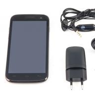
Surely many of you, having bought yourself a new monitor, have wondered what can be done from an old monitor. I was also puzzled by this thought, although I was puzzled by this thought for a very long time, but then there was not such a large selection of different devices. But the Chinese brothers are not asleep and are inventing devices with an unprecedented combination of capabilities. One of these devices was a TV set-top box, which I purchased to add capabilities to my old TV.
- Nexbox A95X TV Box: making Smart TV from a regular TV
But having connected it to the TV set-top box, I was a little disappointed in the clarity of the picture, the set-top box was a little difficult to use, but it helped possibility of remote control from a smartphone or tablet. As a result, the set-top box exceeded my expectations because it was used to watch a bunch of videos from a home server, but the functionality of the set-top box turned out to be much wider and in the end this small box turned a simple TV into computer controlled by remote control. Why am I doing all this? Read on and you will understand everything.
Since my parents do not like to throw away equipment, the Samsung SyncMaster monitor (CRT monitor), after purchasing an LCD monitor, was carefully taken to storage in a barn at the dacha and safely forgotten there. Once again, while putting things in order in the “junk storage”, my father came across a monitor and wondered whether it was possible to watch news on it at the dacha. But he could only get the answer from his advanced son, that is, from me, which he did by calling me one evening.
The monitor itself:
Because a monitor, to put it simply, is a kinescope with a scanner without a radio receiver, which is in the TV, and without a sound system. In other words, it’s a TV, but simplified and lacking some parts. In fact, the monitor contains only a power supply, a scanner and a video amplifier. The only signal source is the VGA(D’SUB) plug, which supplies an analog signal. What does this mean? This means we just have to find a device that will be the source of the signal.
If you have a newer monitor, then it’s probably even easier, because some monitors, if we’re talking about LCD, were equipped with speakers, and newer ones even have an HDMI input. If you have one, then you have a very wide choice of options on how to make a TV out of a monitor.
First experiment: Smart TV from a monitor
Remembering that I had an adapter from HDMI to VGA lying around, I decided to look for it and, having found the adapter, I took the set-top box and went to my parents. After wiping the monitor from dust and dirt, we connected it to the network and then to the set-top box. Despite the small diagonal, using the set-top box was very, very comfortable due to the clearer picture, since the monitor, unlike a TV, is designed for high resolution and the relatively small font is easy to read.
HDMI to VGA adapter
Now you’re probably thinking: “Cool, I’ll buy myself a console!”, but don’t rush. This was just an experiment because we don’t have sound, VGA only provides a picture. Therefore, if you want to go this way, you will have to purchase an HDMI to VGA adapter with an audio output, something like this:

You can order a similar adapter on Aliexpress, here is a link to the seller: buy an HDMI-VGA converter.
When you go to the product page, all you have to do is find the adapter that suits you, it’s not at all difficult, the main thing is to pay attention to the fact that the adapter has a power connector and an audio output.

Thus, we can make a “smart TV” from a monitor, but we will also have to buy active speakers, which will also have to be connected to the audio jack on the adapter. As a result, we will give the monitor a second life and get a good option for the kitchen or work.
Advantages
Within the dacha, there are no advantages due to the lack of full communications.
Flaws
- This set-top box is useless without the Internet.
- Cost of the set-top box.
- The need for an adapter.
- Lack of speakers.
Second experiment: ordering a special TV tuner
Since the place where the barn is located is a place remote from communications and, accordingly, there is no Internet there, the set-top box could not function fully there. In addition, the old father was no longer eager to master another high-tech device and asked to find a TV receiver with a remote control for it.
I present to you a wonderful device that makes a TV from a monitor:
But against the backdrop of recent events with digitalization, this set-top box has lost its relevance.
Digital TV set-top box
Realizing that the presence of digital TV support may be critical for some people, a similar set-top box was found, but with different parameters. You can still connect a monitor to it, but it is no longer possible to connect a computer, and there is no audio output or built-in speaker, which means you will have to connect external speakers.

As you can see, it doesn’t look much different from the previous version, but that’s until we look at the back panel.

As you can see, there is still the same VGA, but in addition to it there is also HDMI. By the way, if you connect this set-top box via HDMI, the sound will come through it. For example, my TV in the kitchen has HDMI, but it does not have digital TV, and if you connect such a set-top box to it, the sound will come from the TV. In addition, this set-top box was also equipped with a USB connector, which makes it possible to watch videos from a flash drive and more.
Just like the first version of a TV tuner for a monitor, this set-top box has RCA (CVBS) sockets.

But unlike the first set-top box, where it is an AV input, in this case these sockets are an AV output, that is, this set-top box, in addition to a monitor and relatively modern TVs, can also be connected to very old TVs.
Features of the console
Since the set-top box accepts digital TV, in addition to everything else, we get a lot of goodies. But first we need to find channels, this is done simply. Press “menu” on the remote control and use the volume buttons to select the appropriate menu item (see photo):

Select “auto search” and press the volume up button. We see the picture:

After some time we will see the found channels and radio stations:

The search for channels is completed, as you can see there are 20 of them in our city, in other cities the number of channels may be different.

By pressing the “info” button on the remote control, you can see what is going on and what will happen next. If you click this button again, you will see more detailed information:

Using the “up” and “down” buttons we switch between gears, and with the yellow and blue buttons we scroll through the description if it is not completely displayed.
To display the program guide, we need to press “EPG” on the remote control:

Use the “left” and “right” buttons to scroll through the channels, and use the “up” and “down” buttons to scroll through the programs.
And here the most interesting thing awaits us. If we press the “OK” button on a particular gear, we will see a strange picture, but if we press the red button, we will see this:

This is adding a schedule for recording a program. Click “OK” again and the task will be added to the queue. The most interesting thing is that we can easily turn off the set-top box, it will turn on itself and record the program. The only thing needed to successfully complete this task is the presence of a flash drive in the USB connector of the set-top box.
A flash drive is also necessary for the “timeshift” function, or “pause” in Russian. Yes, you heard right The set-top box can pause TV. But the set-top box will not be able to keep the TV paused for a long time, since the volume of the recorded stream is limited by the settings of this function. By default the volume is 1Gb, but you can increase it. This is done in the menu:

To do this we need to select “PVR Configure” and click “OK”.

Select “Record device” and click “OK” again.

Actually, here we select our flash drive, and just below we set the amount of memory available for recording.
You've probably wondered why choosing a flash drive if there is only one connector. Nobody forbids us to connect a USB-hub to the connector, and to it a flash drive, an external hard drive, and a card reader.
Three radios are a nice bonus:

Flaws
- No audio output
- There is no built-in speaker, you will have to connect external speakers
- Unable to connect computer
Advantages
- Digital TV reception
- Availability of USB
- Availability of HDMI
- Availability of AV output
In general, to summarize, we can state a wide range of options. The option with an Android set-top box is suitable for those who want to turn a monitor into a TV for the kitchen or other room where there is access to the Internet. Two options for a TV tuner for a monitor are suitable for those who do not want to depend on the Internet and have a very simple solution for watching TV on a monitor. The first option of a TV tuner is suitable for those who want to supplement their computer with the ability to watch TV, and the second option is suitable for those who simply want to give a second life to the monitor and be able to receive digital TV.
Despite the fact that progress is advancing by leaps and bounds, you should not throw away seemingly unnecessary, outdated things, as we see they can still serve you, but in a slightly different capacity. You just need to buy an additional device and a useless thing becomes not only useful, but also acquires an incredibly wide range of capabilities.
Guide from our moderator and regular contributor Nero. This article is a full version of a similar publication in the December issue of the special issue of Hacker magazine dedicated to modding, which also addresses the issue of software.
LCD - Do-it-yourself character-synthesizing display
Editor: PK4Y
Page 1
Unfortunately, most mods have no practical value - they serve only as decoration without bringing any benefit. But the character-synthesizing display, in addition to its decorative function, is also a very useful device.
But what is good about a character-synthesizing display and what is its practical purpose? First of all, it is worth noting the versatility of this device. Using specialized software, you can display almost all system parameters: processor and system temperatures as a whole, fan speed, amount of data transferred, amount of free virtual memory, and much more. Given this versatility, the final costs for this miracle of technology are unlikely to exceed fifteen dollars (this is true when using a 16×2 screen; you can also use 20×4 screens, since the wiring diagrams are no different, but this will increase costs).
From words to deeds
Real modder's kit
What is needed to make this mod? From the tools we need a soldering iron, we also need to purchase solder and rosin (you can use special fluxes). The components you will need are the display itself on a Hitachi HD44780 controller or any compatible one (I used a display from Data Vision on a backlit pm16210 controller), in addition you will need an LPT cable for the printer.
First you need to remove the casings from the ends of the cable using a knife, as shown in the figure.
Cable with covers removed
After this, we unsolder or cut off all the wires soldered to the connector that is inserted directly into the printer.
Now you can start soldering
Now you can start soldering the wires to the display. Just pay attention to how contacts number fifteen and sixteen are located - they are located before the first contact (if you look from left to right, the contacts are in the following order: 16, 15, 1, 2, 3 and so on).
Slightly unusual contact numbering
Here is the table and wiring diagram:
Contact
On LCD 1 2 3 4 5 6 7 8 9 10 11 12 13 14 15 16 What
Solder ground 5v ground pin 16 ground pin 1 pin 2 pin 3 pin 4 pin 5 pin 6 pin 7 pin 8 pin 9 5v ground
Wiring diagram for those who don't like tables
Soldering should be done carefully so that adjacent pads do not touch, otherwise the display may be damaged when connected. After soldering, everything should look something like what is shown in the photo:
Everything is ready to go
I think that for most computer owners, the word “modding” no longer raises questions. Modding is for a computer geek what tuning is for a car driver. Coming from the English modify (modify, change), this concept has grown into a whole direction, with an ever-increasing number of fans. And all thanks to enthusiasts who tried to elevate the boring and nondescript gray boxes that so quickly appeared in our apartments. Moding is plastic surgery for your computer and its peripheral devices. With the help of paint, lighting and some modifications, you can achieve a unique, individual design.
I am not inclined to classify myself as a “modder”, although I visit sites devoted to this topic with great pleasure. In practice, I encountered this completely unexpectedly. But first things first.
Where it all started
It all started with a simple renovation in the kitchen. The TV, which returned to its rightful place after the renovation was completed, ended up right under the ceiling - the fact is that the new refrigerator is twenty centimeters higher than the old one. As a result, watching the morning news with a cup of tea became very difficult. After a week, this began to irritate not only me, but the whole family.
At the family council, it was decided to retire the “old hard worker” and replace him with a new modern liquid crystal “perfection” with further placement of it on the wall. There is nothing easier - go to the nearest consumer electronics store and choose a suitable copy. But the prices for these TVs are very, very impressive. There are, of course, inexpensive models, but they don’t inspire confidence in me. And those that attract attention are in the price range from 17,000 to 32,000 rubles. If you take a closer look at the technical characteristics of televisions in this group, there are almost no differences between the matrices of LCD monitors and the matrices of LCD TVs. And often with the same screen resolution (1024x768), they are inferior to them in brightness, contrast and viewing angles. So what's stopping us from combining an inexpensive LCD monitor with an external TV tuner? It’s decided, we’ll assemble the TV with our own hands.
Selection criteria
Here we need to clearly understand what we want to get in the end, and, based on this, draw up a certain list of conditions by which we will select applicants.
We can immediately divide our conditional list into two groups. Group “A” will include mandatory requirements; failure to fulfill at least one will result in rejection of the applicant. In group “B” there will be desirable ones - those that we can, if necessary, compensate on our own. All this, of course, is subjective, and what I have identified for myself may not coincide with the conditions of others.
Monitor (from 9000 to 10500 rub.)
Group A requirements- Appearance or design - it’s up to anyone. But if we want to get a TV, and not the feeling of a monitor operating in “screen saver” mode, then we should pay special attention to this point.
- Viewing angles. A very important parameter, and we are interested in both horizontal and vertical viewing angles. The higher these values, the more comfortable the viewing experience.
- Brightness and contrast reserve. This parameter, like the previous one, will allow you to achieve satisfactory image quality.
- Illumination uniformity. Screen illumination is not always uniform. In many inexpensive models, the lower part of the screen is noticeably brighter, especially on uniformly dark images. The better this is implemented, the more evenly the light is distributed. The most common backlight is bottom lighting, when the lamp illuminating the matrix is located at the bottom. Another implementation is possible, but it is more relevant to more expensive monitors or widescreen screens.
- Built-in sound system. If you are satisfied with the quality of the sound reproduced by the built-in speakers of the monitor, then the problem of implementing sound for the TV will be solved. Otherwise, in the future you will have to choose an additional sound system, and also look for an additional outlet for it. Powering our TV from three outlets is too much, although this can be easily bypassed if desired.
- Built-in power supply. The external unit will have to be hidden somewhere.
- Monitor stand. Ease of dismantling and non-violation of the design features of the monitor will allow you to maintain the warranty on the device. There are stands that allow you to mount the monitor on the wall. It is also advisable to avoid stands with connectors located on them. But all this is subjective, and everyone will choose what they are looking for.
It is advisable to check all these parameters at a stand, and when purchasing, do not really trust the manufacturer’s technical characteristics - sometimes they are disingenuous.
TV tuner (from 2000 to 3000 rubles)
Group A requirements- Confident, high-quality reception. The resolution of a conventional TV is slightly lower than the resolution of an LCD monitor, and the more noticeable will be the interference associated with a bad antenna cable, unsatisfactory wiring on the panel and uncertain signal reception. If you can try to solve the first two components on your own, then the latter can only be solved by replacing the device.
- Fine tuning. Ability to adjust the channel after automatic tuning.
- Broadcasting system. You need a tuner that automatically adjusts to the broadcast system of the selected television channel, or with the ability to set these values for each channel separately. In accordance with the existing standard in Russia, broadcasting is carried out in the SECAM system, but some regional cable channels use a different encoding for generating color signals.
- Remote control operation. A convenient remote control and the ability to switch from channel to channel with one click of a button, that is, so that when switching to channels from one to nine you don’t have to dial zero at the beginning, and then 1, 2, 3 ... 9. It’s not difficult, but believe me, it’s inconvenient .
- Menu. The more convenient the menu is, the more settings that allow you to make corrections after auto scanning, the easier it is to achieve high-quality picture and sound.
- Russified menu and documentation. Of course, this is an optional requirement, but it allows you to more comfortably navigate the menu and study the documentation.
- Channel preview function. It is very convenient, without flipping through channel by channel, but by looking at the preview window and selecting what you are looking for. As a rule, 9-12 channels are displayed on the screen.
- Return function. Conveniently switch between two channels by pressing just one button. Almost every TV has this feature, and I’m sure many have gotten used to it.
I deliberately do not give specific numerical values for various characteristics, since a discussion on this issue would be inevitable. In addition, for some this may become an unnecessary limitation when choosing devices.
After a short but productive search and comparison, two devices were selected that met my needs. This is BenQ FP591 LCD monitor and GOTVIEW TV tuner - BOX. 
In my opinion, BenQ's designers did a great job - I'm sure no one will remain indifferent when they see this monitor. Plus very decent sound with the SRS function and a built-in card reader. As for the tuner, it is also very good. The model, originally designed for the Russian market, has very good reception and a convenient settings menu in Russian. 

Assembly
Having everything we need in hand, we begin to implement our plans.
The first thing we need to do is check how well all the devices perform their functions. Only after we make sure that our tandem is working can we begin the main part of the work.
The monitor stand is secured with four screws, which will come in handy later. We unscrew the stand and select a place to mount our LCD panel on the wall. The optimal mounting height, taking into account vertical viewing angles, is approximately 1.5-1.6 m from the floor. We outline the contours of the panel, and also mark the depth of the “pocket” where all the connectors will be located. The two top screws that held our panel on the stand will now hold it on the wall, which means we also mark these places with a pencil. Loops for fastening can either be purchased or made using part of the stand for this purpose (I will not dwell on this, since there is nothing complicated at all).
Next, we estimate and mark the place where we will place the tuner. You need to approach this issue creatively and choose a convenient location for the wires from the tuner connectors. I positioned the device so that the connectors faced to the left - for me it was convenient, although not entirely rational. Considering that the top cover of the tuner will be removed, we make a recess in the wall, approximately 30-35 mm. If the wall is concrete, then you can’t do without a hammer drill. It was somewhat simpler for me - the air duct box is made of plaster, and it lends itself well to a simple chisel (taking this into account, the forces had to be controlled so as not to fall a hole into the shaft).
Next, we carry out preliminary assembly to mark the places where we will hide our numerous wires. Then we make a groove and put everything back in its place, but this time with the laying of the wires. 


Next is the most inconvenient, but important moment. Since all the wires will subsequently be closed, and we will not have the opportunity to change their length, we measure as accurately as possible the length of the remaining uncovered wires that will connect the tuner to the monitor. We assemble the entire system and note the length that allowed us to later assemble everything together without interference. 
Considering that in the future the visible area of the tuner and the wires will be covered with a layer of mortar and wallpaper, it is necessary to resolve the issue of ventilation and push-button control of the TV tuner.
The issue of ventilation is easily resolved. One option could be a small oblong hole in the air duct shaft, which can be covered with fiberglass or metal mesh. That's exactly what I did. 

Push-button control of the tuner was implemented as follows. Wires were soldered to the buttons on the device, as well as to the IR receiver and a diode signaling the operation of the device; a regular IDE cable was used for this. Duplicator buttons were placed on the monitor stand, which in turn was a decorative panel covering part of the tuner. 

The panel is attached in the same way as the monitor - using two standard screws on the edges of the stand, which in turn use hinges made from a regular tin can.
Also on the panel were placed: an LED indicator and an IR receiver. To make it easier to dismantle the panel, I connected the wires from the tuner and panel via a standard IDE connector. 

The upper part of the buttons was made of colored diodes from the old hub. In my opinion, it turned out very attractive. But I didn’t backlight these very buttons - the abundance of glowing diodes does not give me pleasant feelings. Very reminiscent of a server rack, although this is a matter of taste. You can duplicate and display all the tuner connectors on the panel. It all depends on whether you want to use them in the future or not. 

Conclusion

As a result, after finishing the painting and plastering work, wallpapering and final installation, we get an excellent multifunctional TV, of very decent quality, at a price of 12,500 rubles. Plus a bonus for our efforts in the form of a built-in card reader. 
The bonus, although exotic, is very useful. Whatever you say, it’s nice, sitting at a good table, in the circle of friends or family, to show on the screen photographs of a recent trip to the sea or to the World Cup. What exactly to show is up to everyone to decide for themselves.
In a classic Russian apartment, the TV is the boss of everything. Usually it is installed in every room. In general, an extra screen never hurts, especially if you already have one in the form of an old LCD monitor.
There are quite a few ways to use a monitor as a TV. You can buy a set-top box, say, Roku. You can increase your budget a little and connect a mini-computer, such as a Raspberry Pi, to an old friend. But there is a more radical method, similar to.
Almost all LCD monitors have an input/output interface called LVDS. If you remove the cover from the monitor and get to the insides, you can see that the connectors are located on a separate board. This board is connected to other components with a fairly flexible cable, similar to an IDE for hard drives.
To upgrade the monitor, you will need to purchase an expansion card for this interface, which has a built-in video decoder. Similar devices can be purchased, for example, or. The decoder and its output will make it possible to play analog (and in the case of a more advanced board, digital) television directly, without the use of various set-top boxes and even a computer.
TTX boards:
- Frequency range - 48.25–863.25 MHz.
- Color system - PAL / SECAM / NTSC.
- Sound system - B/G, D/K, l, M/N, NICAM/A2, BTSC.
- Number of channels - 200.
- Teletext - 10 pages (chip 39 - 10 pages, chip 59 - 1000 pages).
- Input video format (VGA, HDMI) - up to 1920 × 1080 @ 60 Hz.
- Supported video resolutions - 480i, 480p, 576i, 576p, 720p, 1080i, 1080p.
- Audio amplifier output power - 2 × 2.3 W (40) 1 HD + N< 10% @ 1 KHz.
- Supply voltage - 12 V.
Input Connectors:
- Power supply - 12 V.
- VGA input.
- HDMI input.
- Composite video and stereo audio input.
- Audio input when using the TV as a computer monitor.
- Headphone output.
- USB input (for firmware update).
- Input for connecting an antenna or cable.
Actually, the easiest way ends here: the purchased board and monitor are sent to an audio-video equipment repair service. After some time, after paying a small amount, you have a new TV in your hands. All that remains is to install it and connect the antenna or cable TV wire.
A slightly more complicated self-installation path is described in detail by a colleague on the Mysku.ru resource. Let's look at it briefly.

Despite possible problems with installation and configuration, such a monitor upgrade is completely justified. Many people have old, unclaimed 17- and 19-inch devices. The price of such devices on the secondary market is quite low, and the image quality is often no worse than a new TV. It turns out to be an ideal TV for the kitchen, small room or cottage for a minimal price - from 15 to 60 dollars, depending on the configuration and functionality.