A little theory: the pinout of the ISO connector of the radio is determined by the functionality of the contacts in the plugs, in accordance with their numbering. ISO radio connector is a connector for connecting a car's standard radio, certified according to international standards.
Each of these connectors is designed as an eight-pin rectangular plug, but sometimes they are combined into one housing.
When trying to independently replace, for example, a car player from Pioneer with a JVC, car owners are faced with a situation where the wires in the plug are mixed up or do not even fit the shape of the connectors. In order to solve this issue, you need to buy an ISO plug, which is sold at any auto parts store. After that, pinout the head unit connector according to the diagram.
Standard connection diagrams


Standards 1DIN and 2DIN
All car radios can be divided into two types, which are installed by car manufacturers.
- 1DIN standard (single block);
- 2DIN standard (two-block).
Cars of European brands prefer 1DIN.
| №1 | Empty |
| №2 | Empty |
| №3 | Empty |
| №4 | Constant power |
| №5 | Antenna power |
| №6 | Backlight |
| №7 | Ignition |
| №8 | Weight |
And Japanese, American and a number of Chinese car brands use the 2DIN standard.
Dual ISO connector
If you see 2 plugs, then one of the connectors connects the “power” circuits to the radio, that is, current consumption sources are connected to it (in the diagrams with the letter “A” and colored brown). The second connector is needed to connect acoustics (on the diagrams with the letter “B” and painted black).

Adapters for ISO connectors
Now on sale there are many types of different adapters for ISO connectors from one model to another, so you can not solder the plug when connecting it to the radio, but after writing down the model, buy the required adapter.

Pinout diagrams for ISO connectors for Pioneer radios


The model name of the Pioneer car radio, the connection diagrams of which are shown above, can be found out from the file name of each diagram.
Remember: when you connect the device for the first time, you first need to supply power to the radio, and if it lights up and switches as expected, connect the speakers. Otherwise, you can burn not only your audio player, but also your expensive car speakers.
I own a Mazda 2 2004, but with right-hand drive (Singapore version).
The package includes a radio with 6 CDs.
After buying a car, I bought an FM transmitter, then another one, but it burned out just like the first one - saying bang, exhaling smoke and filling the screen black....
I've been listening to the radio for the last couple of years. When we drove away from the city, where the radio waves of the two regions mixed, I turned on the FM transmitter in the navigator.
I’ve been looking towards Yatour for a long time, but I didn’t want to give $50.
A couple of years ago I came across adapters on Aliexpress, but they weren’t much cheaper.
In the summer, a salesman from HongJun Nie's store owed me $10 and asked me to choose a product for that amount.
I bargained for this adapter from him, paying an additional $6, that is, it cost me $16.
I wrote to the seller what kind of car I have, and he indicated which adapter I needed. but later he asked me to send a photo of the plug, saying that there are different ones. 
The parcel arrived in Belgorod in 20 days.
The box included an adapter and a card reader. 

From a discussion at the Mazda Demio Club, I learned that it will be necessary to solder jumpers on the radio board.
Before removing the radio, I decided to check if the Japanese had soldered jumpers for Singapore? Maybe it will work without additional soldering?
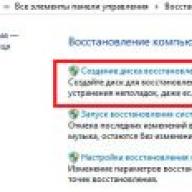
Radio model 
But a miracle did not happen - the radio did not see the device...
I had to solder 9 out of 11 jumpers.
Crooked, with “snot”, but soldered. 
The next day I connected the adapter, pressed the cd button - the light on the adapter lit up, the track time went by, but there was no sound. 
After searching the forum, I found a mention of capacitors and resistors, which may not exist.
Having disassembled the radio for the second time, I discovered that 8 elements were missing.
Taking the payment, I went to the radio workshop. There, an uncle of retirement age tortured me for a long time about what needs to be done, were these elements previously on the board, why do I need this? And suddenly he told me: I won’t do this, I think it’s not necessary, it won’t change anything.))) To which I explained to him that his job is not to think, but to solder the parts.…
I received a refusal from both “phone repair” and “computer repair”.
I bought smd393 resistors, smd 16v 4.7mfu capacitors and flux.
I went home and soldered everything in half an hour.
Crooked, with “snot”, but soldered. (I’m ashamed to post photos of “work”)
I connected everything to the car, pressed the CD button, the light on the adapter lit up, the track time appeared on the screen, and the sound started. 
When connected to a phone, the adapter works as an AUX. When you connect a flash drive, the adapter cuts off AUX and starts playing music from the flash drive.
You can create folders cd1, cd2... my radio sees 6 disks.
You can upload music without folders.
The folder displays 99 tracks, plays subsequent ones, but writes No. 99.
Reads a 16G flash drive.
The buttons on the steering wheel work.
I tried to open the adapter - a crack appeared in the body, it was probably glued together. I didn’t pick any further.
I think this adapter has the right to life.
the product is provided at a discount, therefore point 18
The product was provided for writing a review by the store. The review was published in accordance with clause 18 of the Site Rules.
I'm planning to buy +27 Add to favorites I liked the review +55 +104Microcontroller devices use external memory to store large amounts of data. If you need to store units of megabytes, then serial flash memory chips are suitable. However, for large volumes (tens to hundreds of megabytes), some kind of memory card is usually used. At the moment, SD and microSD cards are the most widespread, and I would like to talk about them in a series of materials. In this article we will talk about connecting SD cards to a microcontroller, and in the following we will figure out how to read or write data to them.
Pinout of SD and microSD cards
SD cards can operate in two modes - SD and SPI. The purpose of the card pins and the connection diagram depend on the mode used. 8-bit AVR microcontrollers do not have hardware support for SD mode, so cards with them are usually used in SPI mode. 32-bit microcontrollers based on the ARM core, for example AT91SAM3, have an interface for working with cards in SD mode, so you can use any operating mode there.
Assigning SD card contacts in SD mode
Assignment of SD card contacts in SPI mode

Assignment of microSD card contacts in SD mode

Assignment of microSD card contacts in SPI mode

Connecting SD and microSD cards to the microcontroller in SPI mode
The supply voltage of SD cards is 2.7 - 3.3 V. If the microcontroller used is powered by the same voltage, then the SD can be connected to the microcontroller directly. The racially correct diagram, compiled by studying the specifications on SD cards and the schematics of various development boards, is shown in the figure below. Cards on development boards from Olimex and Atmel are connected according to this scheme.
The diagram shows exactly the pins of the SD card, not the connector.

L1 - ferrite or choke, rated for current >100 mA. Some install it, some do without it. But what you really shouldn’t neglect is the polar capacitor C2. Because when the card is connected, a current surge occurs, the supply voltage “drops” and the microcontroller can be reset.
There is some ambiguity about pull-up resistors. Since SD cards are made by several manufacturers, there are several specifications for them. Some documents clearly indicate the need for pull-up resistors (even for unused lines - 8, 9), while other documents do not contain these instructions (or I did not find them).
A simplified version of the circuit (without pull-up resistors) is shown in the figure below. This circuit has been tested in practice and is used in Microelectronika boards. It is also used in many amateur projects that can be found on the Internet.

Here the signal lines of the SD card are held high by the microcontroller and the unused lines (8, 9) are not connected anywhere. In theory, they should be pulled up inside the SD card. Further I will build on this scheme.
If the microcontroller is powered by a voltage different from the supply voltage of the SD card, for example 5 V, then the logical levels need to be coordinated. The diagram below shows an example of matching the levels of the card and microcontroller using voltage dividers. The principle of level matching is simple - you need to get 3.0 - 3.2 V from 5 volts.

The MISO - DO line does not contain a voltage divider, since the data on it is transferred from the SD card to the microcontroller, but to protect against fools, you can add a similar voltage divider there too, this will not affect the functioning of the circuit.
If you use a buffer chip, such as the CD4050 or 74AHC125, to match the levels, these disadvantages can be avoided. Below is a circuit where level matching is done using the 4050 IC. This IC has 6 non-inverting buffers. Unused chip buffers are "muffled".

Connecting microSD cards is similar, only their pin numbering is slightly different. I will give only one diagram.

In the diagrams, I looked at connecting SD cards to the microcontroller directly - without connectors. In practice, of course, you cannot do without them. There are several types of connectors and they differ slightly from each other. As a rule, the connector pins repeat the SD card pins and also contain several additional ones - two pins for detecting a card in the slot and two pins for detecting write blocking. These pins are not electrically connected to the SD card in any way and do not need to be connected. However, if they are needed, they can be connected like a regular tact button - one pin to ground, the other through a resistor to the power positive. Or use a microcontroller pull-up resistor instead of an external resistor.

Connecting SD and microSD cards to the microcontroller in SD mode
Well, to complete the picture, I’ll give a diagram for connecting an SD card in its native mode. It allows data exchange at a higher speed than SPI mode. However, not all microcontrollers have a hardware interface for working with the card in SD mode. For example, Atmel's ARM microcontrollers SAM3/SAM4 have it.

The DAT data bus can be used in 1-bit or 4-bit modes.
To be continued...
Message from (vS)
but the link is broken ;)
I tried again, it opens for me...
here's another one....Here is more complete information:
And here’s what I caught, but the simplicity confuses me:
I have long wanted to listen to MP3 discs in the car.Thoughts came to mind from listening to headphones from a portable player (what nonsense!) to installing an MP3 radio to replace the existing one. I didn’t want a cheap MP3 radio, a good one was too expensive.
It was decided to leave the Pioneer DEH P6000R in place and connect the I-River player, which is excellent in my opinion, to the line input. A small difficulty was the lack of a standard line input.
From the conference I learned (the search rocks!) about www.erta.ru, which was stopped by the need to install an additional board into the radio. Well, the price of 50 seemed high. Many people were interested in the issue of organizing a linear entrance at Pioneers. With difficulty I found on the internet a description of the IP-BUS bus, through which the head communicates with the changer and other devices. A linear input can be made on connectors 7, 9, 10 and 11 of this bus. Experience has shown that many involved in IP-BUS research refused to discuss this bus - http://civic.phazer.org/carmp3/, in addition, sites (www.mp3car.com/usersites/arby/installation.html for example) containing information about using this bus turned out to be closed ((If you find this site, please let me know.In addition to making your own linear input, you could use a ready-made device:
Pioneer CD-RB10 Auxiliary Input - $30
http://photofile.ru/default/do?sp=23621&sn=&id=455263
or
Precision Interface Electronics PIO/P-RCA - $20
http://photofile.ru/default/do?sp=23621&sn=&id=455236
However, in our Russian realities the price has increased 2-3 times,
with the condition of delivery in advance payment in a monthIn general, it was decided not to mess with the original devices, but to make it ourselves.
The Pioneer IP-Bus RCA Adapter CD-RB20 block diagram http://photofile.ru/default/do?sp=23621&sn=&id=455310 was found on the website http://pes.homeip.net/, it turned out to be useful from an educational point of view sight, but useless for further experiments. There was no need to repeat this. And the searches on the Internet continued...
The pinout of the IP-BUS connector (http://photofile.ru/default/do?sp=23621&sn=&id=455322) was found on the website http://www.mygizmos.net/frames/hardw...rhardware.html
The connector http://photofile.ru/default/do?sp=23621&sn=&id=455549 was presented more clearly on the website http://www.kisselev.narod.ru/jack.htmlThere was no connector suitable for IP-BUS (http://photofile.ru/default/do?sp=23621&sn=&id=455577) in Chip and Deep. The cable costs (http://www.buy.com/retail/product.as...109705&loc=111) no less than the CD-RB10 adapter, there was no point in buying a cable for one connector.
Poor mouse.
To get the connector, an old, fully functional mouse for the COM port was dissected. She sacrificed her tail for the right cause. The COM connector was cut with a knife. Such knives with a sawing blade are sold for 10 rubles at the subway and last a month at most, I didn’t ask much from him. As a result, I got 4 contacts - too large for the IP-BUS response contacts, so they were crimped with pliers, and then pressed onto the contacts with force.Due to the lack of an audio cable (two-core shielded), a mouse cable was used, to which tuned connectors were soldered on one side, and a 3.5mm jack on the other. Jack was bought the day before for 5 rubles.
I carefully connected the corresponding contacts and isolated them from each other with pieces of plastic.
While walking to the parking lot, I checked in my mind whether I had done everything correctly and whether I had forgotten anything.
The radio is in its place, the new linear input cable is dangling in the glove compartment, the linear input is turned on through the system menu of the radio, an additional AUX source has appeared, the I-River MP3 player is connected to the cable. Well, here's the crucial moment. I turn on the player and enjoy the sound!!!Everything worked the first time. The quality is no different from CD, despite the fact that an unshielded 1 meter long wire is used.
Additionally: I found a description of the Pioneer DEH 6100 7100 http://www.neknn.ru/instructor/uploa...-7100_6100.pdf
instead of a puller, I used a suitable strip from a metal clamp (bought for 20 rubles)Total. costs 5 rubles per jack, 2-3 hours for making the cable and removing and installing the radio. About a week to search for information.
Most laptop motherboards have two SATA connectors on board. One is used to connect a hard drive (HDD), the other for an optical disc drive (ODD). Nowadays, the optical drive has practically lost its relevance, so instead I will connect an additional hard drive. The problem is that the optical drive and hard drive have different connectors. To connect a hard drive instead of an optical drive, you need to make an adapter. This will be discussed in the article.
To make the adapter we will need:
1). Slimline SATA Male connector (13-pin)
You can take it from an old optical drive. If you don't have a drive, take a walk to the nearest repair service. A non-working drive will be given back to you free of charge.
2). Standard SATA Female Cable (7-pin) - SATA Female (7-pin)
Such a cable can be bought at any computer store for 15 rubles. Or you can exchange it with a neighbor who is a computer geek for a can of cold beer.

3). Power connector SATA Female (15-pin)
This connector can be cut from a non-working ATX computer power supply. If there is no power supply, go to a repair service. They will give you about 10 burnt out power supplies.

4). Epoxy adhesive
The most expensive part of our adapter. Sold in auto shops and hardware stores. Instead of epoxy glue, you can use thermal nozzles.

Let's start making the adapter
We disassemble the drive, remove the board with the connector.

The board will be the supporting structure of our adapter. Therefore, we cut it to length and dismantle all components.
Then we cut the SATA (7-pin) cable. Inside we see two shielded pairs for signal reception/transmission.

We strip about 1 centimeter of the cable.

Remove the shielding shell.

From the SATA power connector (15-pin), remove the 12 Volt line (yellow + black), leaving only the 5 Volt line (red + black).

Carefully solder the wires according to the diagram.

We fix the wires with plastic ties.


We fill this whole mess with epoxy glue.

The adapter is ready.

We take the laptop, turn it on and go into the BIOS. We find a list of boot devices. Here we see the line "SATA ODD" - optical drive.

Turn off the laptop and remove the optical drive. Instead of a drive, we connect a hard drive through our adapter.