This table contains the POST codes that are displayed during the full POST procedure.
CF Determine processor type and test read / write CMOS
C0 Chipset and L1-, L2-cache are pre-initialized, programmable
interrupt controller, DMA, timer
C1 The type and amount of RAM is detected
C3 BIOS code is decompressed into a temporary area of RAM
0С BIOS checksums are checked
C5 BIOS code is copied to shadow memory and control is transferred to the Boot Block module
01 XGROUP module is unpacked to physical address 1000: 0000h
02 Initialization of the processor. CR and MSR registers are set
03 I / O resources are determined (Super I / O)
05 Clears the screen and CMOS status flag
06 Coprocessor is checked
07 Determined and tested keyboard controller
08 Keyboard interface is defined
09 Serial ATA controller initialization
OA Determines the keyboard and mouse that are connected to the PS / 2 ports
0B The resources of the AC97 audio controller are being set
OE Tested memory segment F000h
10 Determines the type of flash memory
12 CMOS tested
14 Sets the values for the registers of the chipset
16 The clock generator is initially initialized
18 Determined the type of processor, its parameters and the size of the cache L1 and L2
1B Interrupt vector table is initialized
1C CMOS checksums and battery voltage are checked
1D Power Management System Defined
1F Loading the keyboard matrix (for laptops)
21 The Hardware Power Management system is being initialized (for notebooks)
23 Mathematical coprocessor, floppy drive, chipset initialization are tested
24 The processor microcode is being updated. A resource allocation map is created
Plug and Play devices
25 Initial PCI Initialization: Lists Devices, Find Adapter
VGA, VGA BIOS entry at C000: 0
26 Sets the clock frequency by CMOS Setup. Synchronization is disabled
unused DIMM and PCI slots. Monitoring system is initialized
(H / W Monitor)
27 INT 09h interrupt enabled. The keyboard controller is initialized again
29 MTRR registers are programmed, APIC is initialized. Controller is programmed
IDE. The frequency of the processor is measured. Video System BIOS Extension Called
2B Finding the video adapter BIOS
2D Shows the Award splash screen, information about the type of processor and its speed
33 Keyboard is reset
35 The first DMA channel is being tested
37 The second DMA channel is being tested
39 DMA page registers are tested
3C Configurable controller 8254 (timer)
3E Interrupt controller check 8259
43 Interrupt controller is checked
47 ISA / EISA tires tested
49 The amount of RAM is calculated. Configurable registers for the processor
AMD K5
4E The MTRR registers for Syrix processors are programmed. L2 cache initialized
and APIC
50 USB bus detected
52 RAM is tested and results are displayed. Expanded memory is cleared
53 If CMOS is cleared, the login password is cleared.
55 The number of processors is displayed (for multiprocessor platforms)
57 The EPA logo is displayed. Initialization of ISA PnP devices
59 Determining the virus protection system
5B Display hint for starting BIOS update from floppy disk
5D Starts Super I / O controller and integrated audio controller
60 Enter CMOS Setup if the Delete key was pressed
65 Initializes PS / 2 mouse
69 L2 cache is enabled
6B Chipset registers are configured according to BIOS Setup
6D Assigns resources for ISA PnP devices and COM ports for integrated
devices
6F Initializing and configuring floppy disk controller
75 IDE devices are detected and installed: hard drives,
CD / DVD, LS-120, ZIP, etc.
76 Information about detected IDE devices is displayed
77 Serial and parallel ports are initialized
7A Math coprocessor is reset and ready for operation
7C Defines protection against unauthorized writing to hard drives
7F If there are errors, a message is displayed and waiting for the Delete and F1 keys
82 Allocates memory for power management and updates the ESCD table.
The splash screen with the EPA logo is removed. Password prompted if needed
83 All data is saved from the temporary stack in CMOS
84 Displaying Initializing Plug and Play Cards
85 USB initialization completes
87 SYSID tables are created in the DMI area
89 Installs ACPI tables. Interrupts are assigned to PCI devices
8B Called by BIOS of additional ISA or PCI controllers, except
video adapter
8D Sets the RAM parity parameters by CMOS Setup. Initialized
APM
8F IRQ 12 enabled for hot plugging PS / 2 mouse
94 Completion of initialization of the chipset. Displays the resource allocation table.
Enabling L2 cache. Daylight Saving Time Setting
95 Sets the keyboard auto-repeat rate and Num Lock state
96 Registers are configured for multiprocessor systems (for Cyrix processors).
The ESCD table is created. The DOS Timer is set according to the clock
RTC CMOS.
Boot device partitions are saved for use by the built-in
antivirus.
The speaker announces the end of POST. MSIRQ table is created
FF BIOS INT 19h interrupt in progress. Finding the bootloader in the first sector
boot device
The abbreviated procedure is performed when the Quick Power On Self Test is set in the BIOS.
65 The video adapter is reset. Sound controller, devices are initialized
input / output, keyboard and mouse tested. BIOS integrity is checked
66 Cache is initializing. An interrupt vector table is created.
The power management system is being initialized
67 Checksum CMOS is checked and battery is tested.
Adjusts the chipset based on CMOS parameters
68 The video adapter is initialized
69 Configurable interrupt controller
6A RAM tested (accelerated)
6B EPA logo, processor and memory test results are displayed
70 A prompt for entering BIOS Setup is displayed. The mouse is initialized,
connected to PS / 2 or USB
71 Cache controller initializes
72 Chipset registers are configured. A list of Plug and Play devices is generated.
The floppy controller is being initialized
73 Initializing the hard disk controller
74 Coprocessor is initialized
75 If necessary, the hard disk is write protected
77 If necessary, a password is requested and the messages Press F1 to continue,
DEL to enter Setup
78 Expansion cards are initialized with their own BIOS
79 Platform resources are initialized
7A Generates root table RSDT, device tables DSDT, FADT, etc.
7D Gathering information about boot device partitions
7E BIOS preparing to boot operating system
7F The state of the NumLock indicator is set according to the settings
BIOS Setup
80 INT 19 is called and the operating system is started
******************************************
AMIBIOS 8.0
D0 Initialization of the processor and chipset. Checking Boot Block Checksums
BIOS
D1 Initial initialization of the I / O ports. Keyboard controller
BAT self-test command is transmitted
D2 Disable L1 / L2 cache. The amount of installed RAM is determined
D3 Adjusts the memory regeneration circuits. Allowed to use cache memory
D4 512KB memory test. The stack is established and the exchange protocol is assigned
with cache memory
D5 BIOS code is decompressed and copied to shadow memory
D6 BIOS checksums and Ctrl + Home keystrokes are checked
(BIOS recovery)
D7 Control is transferred to the interface module, which unpacks the code into the area
Run-time
D8 The executable code is unpacked from flash-memory into RAM. Persists
CPUID information
D9 The decompressed code is transferred from the temporary storage area to the segments
0E000h and 0F000h RAM
DA CPUID registers are restored. POST is pushed to RAM
E1 – E8, EC – EE Errors related to system memory configuration
03 Prohibited processing of NMI, parity errors, signaling to the monitor.
Reserved area for GPNV event log, set initial
variable values from BIOS
04 Battery health is checked and CMOS checksum is calculated
05 The interrupt controller is initialized and the vector table is built
06 Timer is being tested and prepared for operation
08 Keyboard is being tested (keyboard lights are blinking)
C0 Initialization of the processor. It is forbidden to use the cache memory.
Determined by APIC
C1 For multiprocessor systems, the processor responsible for starting the system is determined
C2 The processor assignment to start the system is ending. Identification with
using CPUID
C5 The number of processors is determined, their parameters are adjusted
C6 Initializes cache memory for faster POST progress
C7 Initialization of the processor is completed
0A Keyboard controller determined
0B Search for a mouse connected to the PS / 2 port
0C Checks for keyboard presence
0E Various input devices are detected and initialized
13 Initial initialization of chipset registers
24 The platform-specific BIOS modules are unpacked and initialized.
Interrupt vector table is created and interrupt handling is initialized
2A DIM mechanism defines devices on local buses. Preparing for
initialization of the video adapter, the resource allocation table is built
2C Detect and initialize the video adapter, the video adapter is called by the BIOS
2E Search and initialize additional I / O devices
30 Preparing for SMI Processing
31 ADM is initialized and activated
33 The lightweight boot module is initialized
37 Display AMI logo, BIOS version, processor, key prompt to enter
in BIOS
38 Various devices on local buses are initialized with the help of DIM
39 Initializing DMA controller
3A Set the system time according to the RTC clock
3B RAM is tested and results are displayed
3C Chipset registers are configured
40 Serial and parallel ports are initialized, math
coprocessor, etc.
52 Memory test results update RAM data in CMOS
60 BIOS Setup sets the NumLock state and configures the parameters
autorepeat
75 The procedure for working with disk devices is started (interrupt INT 13h)
78 Creates a list of IPL devices (from which the operating system can be loaded)
7C ESCD extended system configuration tables are created and written to NVRAM
84 Logging POST Errors
85 Non-fatal error messages are reported.
87 If necessary, the BIOS Setup is launched, which is previously unpacked into RAM
8C Chipset registers are configured in accordance with BIOS Setup
8D ACPI tables are built
8E Configurable non-maskable interrupt service (NMI)
90 SMI is finally initialized
A1 Clearing data that is not needed when the operating system boots
A2 EFI modules are being prepared to interact with the operating system
A4 According to BIOS Setup, the language module is initialized
A7 POST summary table is displayed
A8 Sets the state of the MTRR registers
A9 Wait for keyboard commands if needed
AA POST interrupt vectors are removed (INT 1Ch and INT 09h)
AB Determines devices for loading the operating system
AC Final stages of chipset configuration in accordance with BIOS Setup
B1 Configurable ACPI interface
00 INT 19h interrupt handling is called (search for boot sector, boot OS)
******************************************
PhoenixBIOS 4.0
02 Verify Real Mode
03 Disable Non-Maskable Interrupt (NMI)
04 Get CPU type
06 Initialize system hardware
08 Initialize chipset with initial POST values
09 Set IN POST flag
0A Initialize CPU registers
0B Enable CPU cache
0C Initialize caches to initial POST values
0E Initialize I / O component
0F Initialize the local bus IDE
10 Initialize Power Management
11 Load alternate registers with initial POST values
12 Restore CPU control word during warm boot
13 Initialize PCI Bus Mastering devices
14 Initialize keyboard controller
16 (1-2-2-3) BIOS ROM checksum
17 Initialize cache before memory autosize
18 8254 timer initialization
1A 8237 DMA controller initialization
1C Reset Programmable Interrupt Controller
20 (1-3-1-1) Test DRAM refresh
22 (1-3-1-3) Test 8742 Keyboard Controller
24 Set ES segment register to 4 GB
26 Enable A20 line
28 Autosize DRAM
29 Initialize POST Memory Manager
2A Clear 512 KB base RAM
2C (1-3-4-1) RAM failure on address line xxxx
2E (1-3-4-3) RAM failure on data bits xxxx of low byte of memory bus
2F Enable cache before system BIOS shadow
30 (1-4-1-1) RAM failure on data bits xxxx of high byte of memory bus
32 Test CPU bus-clock frequency
33 Initialize Phoenix Dispatch Manager
34 Disable Power Button during POST
35 Re-initialize registers
36 Warm start shut down
37 Re-initialize chipset
38 Shadow system BIOS ROM
39 Re-initialize cache
3A Autosize cache
3C Advanced configuration of chipset registers
3D Load alternate registers with CMOS values
40 CPU speed detection
42 Initialize interrupt vectors
45 POST device initialization
46 (2-1-2-3) Check ROM copyright notice
48 Check video configuration against CMOS
49 Initialize PCI bus and devices
4A Initialize all video adapters in system
4B QuietBoot start (optional)
4C Shadow video BIOS ROM
4E Display BIOS copyright notice
50 Display CPU type and speed
51 Initialize EISA board
52 Test keyboard The keyboard is being tested
54 Set key click if enabled
55 Initialize USB bus
58 (2-2-3-1) Test for unexpected interrupts
59 Initialize POST display service
5A Display prompt “Press F2 to enter SETUP”
5B Disable CPU cache
5C Test RAM between 512 and 640 KB
60 Test extended memory
62 Test extended memory address lines
64 Jump to UserPatch1
66 Configure advanced cache registers
67 Initialize Multi Processor APIC
68 Enable external and CPU caches
69 Setup System Management Mode (SMM) area
6A Display external L2 cache size
6B Load custom defaults (optional)
6C Display shadow-area message
6E Display possible high address for UMB recovery
70 Display error messages Error messages are displayed
72 Check for configuration errors
76 Check for keyboard errors
7C Set up hardware interrupt vectors
7D Initialize hardware monitoring
7E Initialize coprocessor if present
80 Disable onboard Super I / O ports and IRQs
81 Late POST device initialization
82 Detect and install external RS232 ports
83 Configure non-MCD IDE controllers
84 Detect and install external parallel ports
85 Initialize PC-compatible PnP ISA devices
86 Re-initialize onboard I / O ports
87 Configure Motheboard Configurable Devices (optional)
88 Initialize BIOS Data Area
89 Enable Non-Maskable Interrupts (NMIs)
8A Initialize Extended BIOS Data Area
8B Test and initialize PS / 2 mouse
8C Initialize floppy controller
8F Determine number of ATA drives (optional)
90 Initialize hard-disk controllers
91 Initialize local-bus harddisk controllers
92 Jump to UserPatch2
93 Build MPTABLE for multi-processor boards
95 Install CD ROM for boot
96 Clear huge ES segment register
97 Fixup Multi Processor table
98 (1-2) Search for option ROMs. One long, two short beeps on checksum failure
99 Check for SMART Drive (optional)
9A Shadow option ROMs
9C Set up Power Management
9D Initialize security engine (optional)
9E Enable hardware interrupts
9F Determine number of ATA and SCSI drives
A0 Set time of day
A2 Check key lock
A4 Initialize Typematic rate
A8 Erase F2 prompt
AA Scan for F2 key stroke
AC Enter SETUP
AE Clear Boot flag
B0 Check for errors
B2 POST done - prepare to boot operating system
B4 (1) One short beep before boot
B5 Terminate QuietBoot (optional)
B6 Check password (optional)
B9 Prepare Boot
BA Initialize DMI parameters
BB Initialize PnP Option ROMs
BC clear parity checkers
BD Display MultiBoot menu
BE Clear screen (optional)
BF Check virus and backup reminders
C0 Try to boot with INT 19
C1 Initialize POST Error Manager (PEM)
C2 Initialize error logging
C3 Initialize error display function
C4 Initialize system error handler
C5 PnPnd dual CMOS (optional)
C6 Initialize notebook docking (optional)
C7 Initialize notebook docking late
D2 Unknown interrupt
E0 Initialize the chipset
E1 Initialize the bridge
E2 Initialize the CPU
E3 Initialize system timer
E4 Initialize system I / O
E5 Check force recovery boot
E6 Checksum BIOS ROM
E7 Go to BIOS
E8 Set Huge Segment
E9 Initialize Multi Processor
EA Initialize OEM special code
EB Initialize PIC and DMA
EC Initialize Memory type
ED Initialize Memory size
Ee shadow boot block
EF System memory test
F0 Initialize interrupt vectors
F1 Initialize Real Time Clock
F2 Initialize video
F3 Initialize System Management Mode
F4 (1) Output one beep before boot
F5 Boot to Mini DOS
F6 Clear Huge Segment
F7 Boot to Full DOS
"Internet-Shop site" is a wholesale and retail trade center with carefully selected unique and high-quality goods. Why you should choose us:
- We carefully select the assortment of goods for your convenience in choosing only unique, high-quality and proven goods.
- We have been working with the best postal delivery operators for a long time and productively. Delivery is carried out by state postal services, which means that you can receive your order in Moscow or any other capital, and in the smallest village of any country.
- The main priority of our team is 100% customer satisfaction with product, service and after-sales support, as thousands of our customers have seen.
- Only with us you can get an unconditional refund within 30 days after receiving the parcel, without explaining the reasons, i.e. if you just don't like the product.
Chinese electronics online store website
The category, which includes, is very widely represented in our store. The category presents Chinese phones for 2 sim cards other. Chinese manufacturers have gone further in the technical saturation of phones, now Chinese phones with TV, Wi-Fi and even GPS are being sold. As a result, Chinese-made mobile phones are equipped with more features than their competitors.
The support of two SIM cards in the phone allows you to use two phone numbers in one, thanks to two radio modules, and you can use mobile communication economically, using more favorable tariffs for calls in two networks.
The multimedia functions of your phone allow you to use your phone as a player for playing video, audio files and watching TV. The Wi-Fi function will allow you to access the Internet using many free hotspots in hotels, restaurants, train stations. It will be very convenient for motorists to use one device for calls and for GPS navigation. Just imagine how many individual devices a modern one can replace Chinese phone.
Our Chinese electronics online store makes free delivery by mail to all regions of the CIS and the world.
Let's try to figure it out together and put everything on the shelves. Let us assume that the reader is already familiar with what the "POST controller principle of operation" is based on. Then what is a POST card for a motherboard repairer?
It's a TOOL!
Most importantly, the POST card is tool for the motherboard repairer. While not an obvious statement, it does not cease to be fact: for those who are constantly involved in the repair and maintenance of motherboards / computers, the POST-card is the same tool like a voltmeter, oscilloscope, etc. And the greater the flow of motherboards-computers passes through your hands, the more important the POST-card itself and its quality.
Indirect confirmation - the instrumental properties of POST cards are in demand not only at the hardware level, but also among programmers when developing and debugging software. In cases where the output of checkpoints to console devices is difficult for some reason, the use of POST cards allows you to get a real picture of what is happening and trace the software product with minimal costs for developing the source code.
However, do not forget that the POST card is installed in broken motherboards, and as a result of this, it happens, and itself POST card fails... Therefore, for those who cannot afford to burn an expensive fancy POST card in motherboards that have just arrived for repair, it is recommended to purchase cheap POST cards for primary diagnosis, and in more complex cases, use an expensive POST card with additional features.
The simplest postcard is made from "scrap materials" in just half an hour. At one time he himself made a similar one on the basis of an old ISA-shny Trident-9000 (or figurative to him - I don’t remember exactly) with soldered-on "3-dimensional" mounting of LEDs. The design turned out to be unreliable (although it could easily "work right away") and after a certain number of "insertion-removal" cycles, one had to look for another break or short circuit. Therefore, it is better to solder something more "serious", there are a lot of options, for example, on the site of Roman Skripnik, a great connoisseur and enthusiast of PC diagnostics.
The pages of this site provide a diagram and description of the simplest POST Card for the ISA bus. The positive side is not only a detailed presentation of the subject, but also a simple, but very useful, almost irreplaceable program for testing POST Card.
POST cards for PCI, as well as many other things, can be made by yourself, i.e. go all the way "from beginning to end": draw-etch-solder-flash. You can, making your life easier, limit yourself only to soldering. To do this, you need to purchase a ready-made kit. Having spent some money, you can purchase a completely finished product and enjoy diagnostics using a "proprietary" POST controller.
mini PCI POST Card
Diagnostics for the mini PCI bus is in demand only for repairing mobile platforms, so not too many companies decide to release them. In addition, the standard for this bus appeared only in 1999, which means that all notebooks released before this date are not equipped with a mini PCI slot. Most modern laptops can use mini PCI Express, making it unusable for older, outdated mini PCI diagnostic devices.
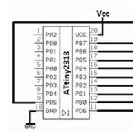
To work with laptops (with an external LPT connector on board), LPT postcards are used. Their device is primitive to the point of disgrace, therefore, on the one hand, it is not difficult to pile one yourself, and on the other hand, the justification for the production of such serially (from the point of view of the manufacturer's ability to earn money) is rather controversial. And therefore these are present, as a rule, for completeness of the set of solutions of all types. Above is the schematic diagram of the Debug Card specified in the service manual for the Mitac 8170 laptop.
PCMCIA POST Card
Let's dream up and imagine that this is possible! Why not? The word is up to the BIOS developers ...
The device for repair and testing of personal computers (PC) POST Card PCI is used to diagnose malfunctions during the repair and modernization of computers, as well as peripheral systems. It will find wide application in any electronic systems based on computers such as IBM PC (or compatible with them).
General information
POST Card PCI (Fig. 1) is a PC expansion card that can be installed in any free PCI slot (33 MHz) and is designed to display POST codes generated by the PC BIOS system in a user-friendly form.
Rice. 1. Appearance of the device
Thanks to the use of FPGA (Programmable Logic Integrated Circuit) from Altera, it became possible to create a device that is simple and accessible for repetition by radio amateurs.
In addition, the device can be used as a microcircuit tester. To do this, it provides a 44-pin panel for the microcircuit.
The POST Card PCI device has the following specifications:
- Supply voltage, V +5
- Consumption current, mA
- PCI bus frequency PC, MG c 33
- Diagnostic port address 0080h
- Indication of POST codes (in hexadecimal) 1 byte
- Indication of signals PG bus RST (left point), CLK (right point of the indicator)
- Power supply voltage indicators, V +5, +12, -12, +3.3
- Compatible with motherboards based on Intel, VIA, SIS chipsets
- PCB size, mm 112x90
The basis of the PCI POST Card is the DD1 FPGA (Fig. 1, 2), which implements a simplified PCI Target device that supports writing to the output port and automatic configuration (Plug & Plug) sufficient for the device to function. FPGA Altera EPM3064ALC44-10 is included in the set and is programmed by MASTER KIT specifically to work in POST Card PCI. A +3.3 V voltage regulator is assembled on the DD2 microcircuit to power the FPGA. Information from the FPGA is output in sequential form and recorded in the registers DD4, DD5. Their outputs are connected through limiting resistors to a double 7-segment indicator HL1, on which POST codes are displayed. To ensure that the process of indicating POST codes is not disturbed in the event of a failure in the generation of PCI CLK on a faulty motherboard, a separate generator on the DD3 chip is included in the POST Card PCI.

Rice. 2. Schematic diagram of the POST CARD PCI device
LEDs connected through limiting resistors indicate the presence of voltages +3.3, +5, + 12 and -12 V on the PCI bus.
Principle of operation
Each time the IBM PC-compatible PC is powered on and before the operating system boots, the computer's processor performs a BIOS procedure called Power On Self Test (POST). The same procedure is also performed when you press the RESET button or when you restart the computer softly. In some special cases, in order to reduce the PC boot time, the POST procedure can be slightly shortened in time, for example, in the "Quick Boot" mode or when waking up from the "sleep" mode (Hibernate).
The main purpose of the POST procedure is to check the basic functions and subsystems of the PC (memory, processor, motherboard, video controller, keyboard, floppy and hard disks) before loading the operating system. This insures the user against trying to work on a faulty system, which could lead, for example, to the destruction of user data on the hard disk. Before starting each of the tests, the POST procedure generates a POST code, which is displayed at a specific address in the address space of PC input / output devices. If a malfunction is detected in the device under test, the POST procedure simply "hangs", and the previously displayed POST code unambiguously determines on which of the tests the "hang" occurred. Thus, the depth and accuracy of diagnostics using POST codes are completely determined by the depth and accuracy of tests of the corresponding POST procedure of the computer BIOS.
Some BIOS Trouble Codes
The table lists some of the AMI BIOS codes that reflect the most common PC malfunctions.
table
| Code | Malfunction |
| System memory configuration error (fatal error) |
|
| System memory configuration error (beep) |
|
| Early initialization of the keyboard controller |
|
| VGA BIOS initialization error |
|
| CGA video memory test error |
|
| CGA Scanning Circuits Test Error |
|
| Error in video memory or scanning circuits |
|
| Disable IRQ12 if PS / 2 mouse is missing |
|
| Error message indication |
|
| Determination of memory type, total size and allocation by lines |
|
| Error messages in previous stages of initialization |
In addition to the above POST codes, messages about events during the execution of the Device Initialization Manager (DIM) are output to the diagnostic port. There are several breakpoints that display the initialization status of the system or local buses.
If an error is detected in the system memory configuration (DE or DF codes), the DE code, DF code, and a configuration error code are output to port 80h sequentially in an infinite loop, which can take the following values:
00 - RAM was not found;
01 - DIMMs of various types are installed (for example, EDO and SDRAM);
02 - reading SPD content failed;
03 - the module does not meet the requirements for operation at a given frequency;
04 - the module cannot be used in this system;
05 - information in SPD does not allow using installed modules;
06 - An error was detected in the low memory page.
Practical Troubleshooting Using the POST Card Tester
First of all, when the power is turned on, before starting the POST procedure, the system must be reset with the RST (RESET) signal, which is indicated on the POST Card by a short blinking of the left dot on the indicator. Consider a few of the most popular PC malfunctions and how to localize them.
POST codes are not displayed
If the computer malfunctions in the most difficult case, the reset either does not work at all, or it does, but no POST codes are displayed on the indicator.
It is recommended that you turn off the computer immediately and remove all additional cards and cables, as well as RAM memory from the slots of the motherboard, leaving only the motherboard itself connected to the power supply with the processor and POST Card installed. If the next time you turn on the computer, the system resets normally and the first POST codes appear, the problem is obviously with the temporarily removed computer components. Possibly, the loops are connected incorrectly. By inserting sequentially memory modules, a video adapter, and then other cards, and observing the POST codes on the indicator, a faulty module is found.
Even the initial system reset does not pass (on the POST Card indicator at the very beginning of the test, the left indicator point does not light up for a short time)
In this case, either the computer's power supply is faulty, or the motherboard itself (the RESET signal formation circuits are faulty). The exact cause can be determined by connecting a known-good power supply to the motherboard.
The reset signal passes, but no POST codes are displayed on the indicator (the system is tested, consisting only of the motherboard, processor, POST Card and power supply)
If the motherboard is new, the cause may be incorrectly installed switches on the motherboard. If all switches and the processor are set correctly and the motherboard does not start, the processor should be replaced with a known good processor. If this does not help, then we can conclude that the motherboard or its components are faulty (for example, the cause of the malfunction may be damage to the information in the Flash-BIOS).
PC malfunctions determined with the pOsT Card tester
After turning on the power of the computer (or pressing the RESET button) and before the first POST-code appears, a special symbol is displayed on the POST Card indicator (see Fig. 3), which indicates that there is no PC output of any POST-codes. This feature of this POST Card makes diagnostics easier and allows you to visually determine whether the computer starts at all. In addition, the same symbol is displayed during a PCI bus software reset to latch the RST signal flow. The dots on the 7-segment POST Card display the PCI bus RST and CLK signal states. The ignition of the right point corresponds to the presence of an active CLK signal of the PCI bus, the ignition of the left point corresponds to the presence of an active signal RST

Rice. 3. Indication on the POST Card that there is no PC output of any POST codes
If the computer is working properly, when the power is turned on, the system must first be reset with the RESET signal (which is indicated on the POST Card with special characters), then the computer must be started with sequential passage of all POST codes. If the computer malfunctions, in the most difficult case, the reset either does not work at all, or it passes, but no other POST codes are displayed on the indicator.
In this case, it is recommended that you turn off your computer immediately, disconnect all additional boards and cables, and memory from the motherboard, leaving only the motherboard connected to the power supply with the processor and POST Card installed.
If the next time you turn on the computer, the system resets normally and the first POST codes appear, then the problem is with the temporarily removed computer components. Perhaps the loops are connected incorrectly (especially often the IDE loop is inserted upside down).
The memory module, video adapter, and other cards are sequentially installed and, observing the POST codes, they find the faulty module.
For example, if the memory is faulty for computers with AMI BIOS, the POST code sequence is usually fixed at the d4 code; with AWARD BIOS - on codes C1 or C6. It happens that in this case it is not the memory module itself that is faulty, but the motherboard - the reason lies in poor contact in the SIMM / DIMM connectors (the contacts are bent / closed), or the module is not fully inserted into the connector.
If the video adapter for computers with AMI BIOS is faulty, the sequence of POST codes is fixed at codes 2C, 40 or 2A, depending on the BIOS modification, or these codes are absent, and the monitor does not have the corresponding video card initialization strings (indicating the type, amount of memory and the manufacturer of the video adapter ).
Similarly, for computers with AWARD BIOS, if the video adapter fails, the sequence of POST codes is either fixed at code 0d, or "skips" this code. If the initialization of the memory and video adapter went well, install the remaining cards one by one and, connecting the loops, based on the readings of the POST Card indicator, determine which of the components "hooks up" the system bus and prevents the computer from booting.
In fig. Figure 4-6 shows the POST Card indication for various errors.

Rice. 4. Video memory error code (during testing, the video memory card was removed from the system unit)

Rice. 5. Error code of the "Mouse" manipulator (during testing, the manipulator was disabled)

Rice. 6. RAM error code (during testing, the memory module was removed from the motherboard)
Sequence of actions to resuscitate a PC using the POST Card PCI tester
1. Turn off the power to the failed computer.
2. Install the POST Card in any free slot on the motherboard.
3. Power on the PC and read the corresponding POST code from the POST-Card indicator, which interrupts ("hangs") the computer boot.
4. Using the tables of POST codes, if necessary, determine which of the tests encountered problems and their probable causes.
5. With the power off, rearrange the cables, RAM memory modules and other components with connectors in order to eliminate the malfunction.
6. Repeat points 3, 4, 5 for stable POST procedure and normal loading of the operating system.
7. With the help of software utilities, final testing of hardware components is carried out, and in the case of "floating" (unstable) errors - a long run of the corresponding software tests.
Greetings, dear Habrovites!
Not the first year I have been engaged in diagnostics and resuscitation of desktops and laptops, mainly at the client's home. Over time, the conclusion suggests itself that you need to have a suitcase with you, and perhaps even a suitcase with components for diagnosing a faulty piece of iron. Some may object to me - “You can do without accessories! Experience allows you to carry out diagnostics without them! ". This is partly true, but it does not give one hundred percent accuracy, this is a fact.
Rely on speaker POST codes? Not always possible specifically determine what he swears at. For example, one long two short beeps of the speaker signal a malfunction of the video system, but this does not always mean a malfunction of the video card itself. There are, for example, problems with add. power supply to this very video card, and this is already a malfunction of the power supply.
Here I will stop and tell dear readers what the speaker signals are.
When you turn on the computer, the BIOS (basic input / output system) starts up - a fact known to everyone, but it will not be superfluous to mention. The BIOS includes a program called POST (power on self testing). As the name suggests, the program is intended for initial diagnostics of motherboard devices and ports.
The POST initialization procedure is accompanied by displaying an image on the monitor:
After passing the POST, we see:

During the execution, POST generates the so-called POST code, which is written into a special diagnostic register.
Actually, the speaker signals are error codes during POST, if POST is performed without errors, we hear one short beep.
We pass to the subject.
POST cards.
A POST card is an expansion card, the most common are PCI cards:
There are also miniPCI cards (for laptops):

And there are cards for LPT (they require additional power supply via USB):

Having on hand a desktop with a remarkable diagnosis "does not turn on" (not to be confused with "does not start"), most often, first, uncritical peripherals are sequentially turned off - sound, tuner, network card, hard drives, drives.
Then, if no malfunctions are identified in the process, the replacement of components begins: RAM, video card, processor (yeah, that same suitcase with pieces of iron).
But now we have a POST card in our hands instead of a suitcase with iron, we save time bypassing the above procedure with replacing / disabling the iron (we save an average of 40 minutes, I note that after disconnecting one piece of hardware, at least one turn-on cycle is performed).
Actually, we insert our wonderful map and watch what happens.
And the following happens - on the map board we have post codes that indicate to us what is being tested at the moment. Having reached the faulty element, the POST procedure stops and a code remains on the display, so a manual with POST codes is most often attached to the subject (they differ depending on the manufacturer and BIOS version).
By comparing the error code with its decoding, most often we get the final diagnosis, such as: faulty memory, processor, or a component on the motherboard.
I propose to write a series of articles on diagnostics, if the topic is of interest to Habrovites.